1996 CHRYSLER VOYAGER sensor
[x] Cancel search: sensorPage 1278 of 1938

CAUTION: When using the ASD Fuel System Test,
The Auto Shutdown (ASD) Relay will remain ener-
gized for 7 minutes or until the ignition switch is
turned to the OFF position, or Stop All Test is
selected.
EXHAUST MANIFOLDSÐ3.3/3.8L ENGINE
REMOVAL
(1) Disconnect battery negative cable.
(2) Remove accessory drive belt. Refer to Accessory
Drive section located in Group 7 Cooling System for
procedure.
(3) Remove generator.
(4) Raise vehicle and disconnect exhaust pipe
from rear (cowl side) exhaust manifold at flex-joint.
(5) Disconnect down stream oxygen sensor connec-
tor.
(6) Lower exhaust system to gain access to rear
manifold.
(7) Separate EGR tube from rear manifold and
disconnect Heated Oxygen Sensor lead wire (Fig. 45).
(8) Remove heat shield from rear engine mount.
(9) Remove Generator/Power Steering Support
Strut (Fig. 45).
(10) Remove bolts attaching crossover pipe to
manifold (Fig. 45).
(11) Disconnect up stream oxygen sensor connec-
tor.
(12) Remove bolts attaching rear manifold to cyl-
inder head and remove manifold.
(13) Lower vehicle and remove screws attaching
front heat shield to front manifold (Fig. 46).
(14) Remove bolts fastening crossover pipe to
front exhaust manifold and nuts fastening manifold
to cylinder head. Remove assemblies (Fig. 47).
(15) Inspect and clean manifold. Refer to Cleaning
and Inspection outlined in this section for proce-
dures.
INSTALLATION
(1) Install rear exhaust manifold and tighten
attaching bolts to 23 N´m (200 in. lbs.).
(2) Install generator.
NOTE: Inspect crossover pipe fasteners for dam-
age from heat and corrosion. Replace if necessary.
(3) Using new gasket attach crossover pipe to
exhaust manifold and tighten bolts to 54 N´m (40 ft.
lbs.) and connect oxygen sensor lead (Fig. 45).
(4) Install EGR Tube and Generator/Power Steer-
ing Strut (Fig. 45).
(5) Using new gaskets install front exhaust mani-
fold and tighten attaching bolts to 23 N´m (200 in.
lbs.).(6) Attach exhaust crossover with a new gasket
and tighten fasteners to 54 N´m (40 ft. lbs.) (Fig. 47).
(7) Connect up stream oxygen sensor connector.
(8) Install exhaust system.
Fig. 45 EGR Tube, Heated Oxygen Sensor and
Generator/Power Steering Strut
Fig. 46 Heat ShieldÐFront
Fig. 47 Crossover Pipe
11 - 16 EXHAUST SYSTEM AND INTAKE MANIFOLDNS
REMOVAL AND INSTALLATION (Continued)
Page 1279 of 1938
(9) Attach exhaust pipe to exhaust manifold using
new gasket and tighten bolts to 28 N´m (250 in. lbs.).
(10) Connect down stream oxygen sensor connec-
tor.
(11) Install front manifold heat shield and tighten
attaching screws to 12 N´m (105 in. lbs.) (Fig. 46).
(12) Install accessory drive belt. Refer to Accessory
Drive section located in Group 7 Cooling System for
procedure.
(13) Connect battery negative cable.
CLEANING AND INSPECTION
INTAKE MANIFOLD
INSPECTION
Check for:
²Damage and cracks of each section.
²Clogged water passages in end cross-overs (if
equipped).
²Check for cylinder head mounting surface distor-
tion using a straightedge and thickness gauge. Refer
to specifications for warpage specification.
CLEANING
Remove the gasket material from the manifold sur-
faces.
Be careful not to gouge or scratch the sealing sur-
face.
EXHAUST MANIFOLD
INSPECTION
Inspect exhaust manifolds for damage or cracks
and check distortion of the cylinder head mounting
surface and exhaust cross-over mounting surface
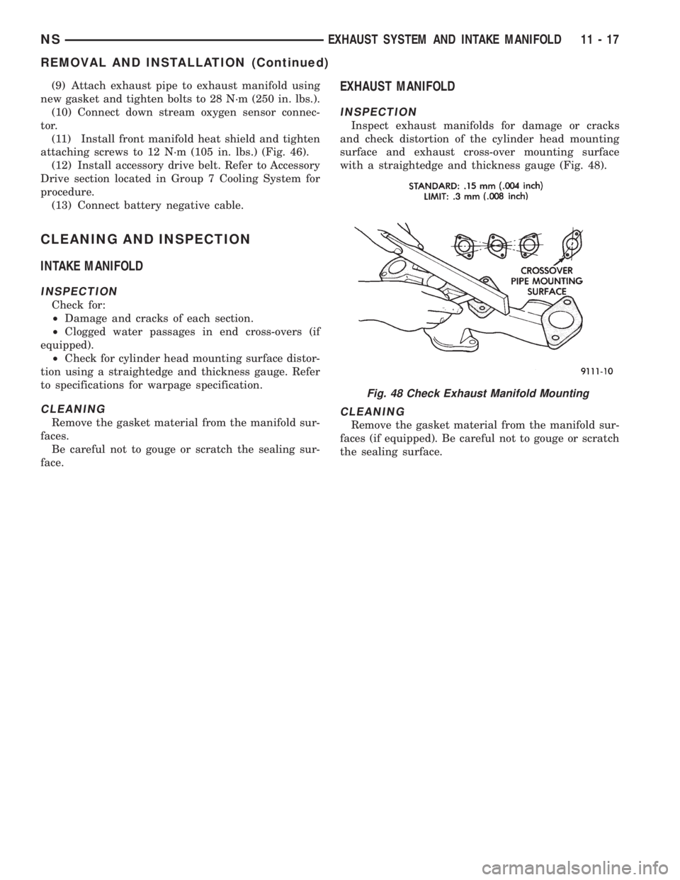
with a straightedge and thickness gauge (Fig. 48).
CLEANING
Remove the gasket material from the manifold sur-
faces (if equipped). Be careful not to gouge or scratch
the sealing surface.
Fig. 48 Check Exhaust Manifold Mounting
NSEXHAUST SYSTEM AND INTAKE MANIFOLD 11 - 17
REMOVAL AND INSTALLATION (Continued)
Page 1283 of 1938
FRAME
INDEX
page page
REMOVAL AND INSTALLATION
FRONT CROSSMEMBER MOUNT BUSHINGS . . . 5
FRONT CROSSMEMBER................... 3SPECIFICATIONS
FRAME AND BODY OPENING DIMENSIONS.... 5
REMOVAL AND INSTALLATION
FRONT CROSSMEMBER
The front suspension crossmember must be
installed in the design location to achieve proper
front end suspension alignment. If the crossmember
is removed without applying reference marks on the
frame rails, align the crossmember according to the
dimensions provided in this group.
NOTE: If the caged nuts in the frame rails become
damaged and cannot be reused, a replacement nut
can be obtained through a MoparTParts supplier.
REMOVAL
(1) Disconnect battery negative cable.
(2) Remove steering column lower cover from
instrument panel. Refer to Group 8E, Instrument
Panel and Systems.
(3) Remove knee blocker reinforcement. Refer to
Group 8E, Instrument Panel and Systems.
(4) Position steering so front wheels are straight
ahead.
CAUTION: Do not rotate steering wheel after disen-
gaging lower coupling from steering gear, damage
to airbag clock spring can result.
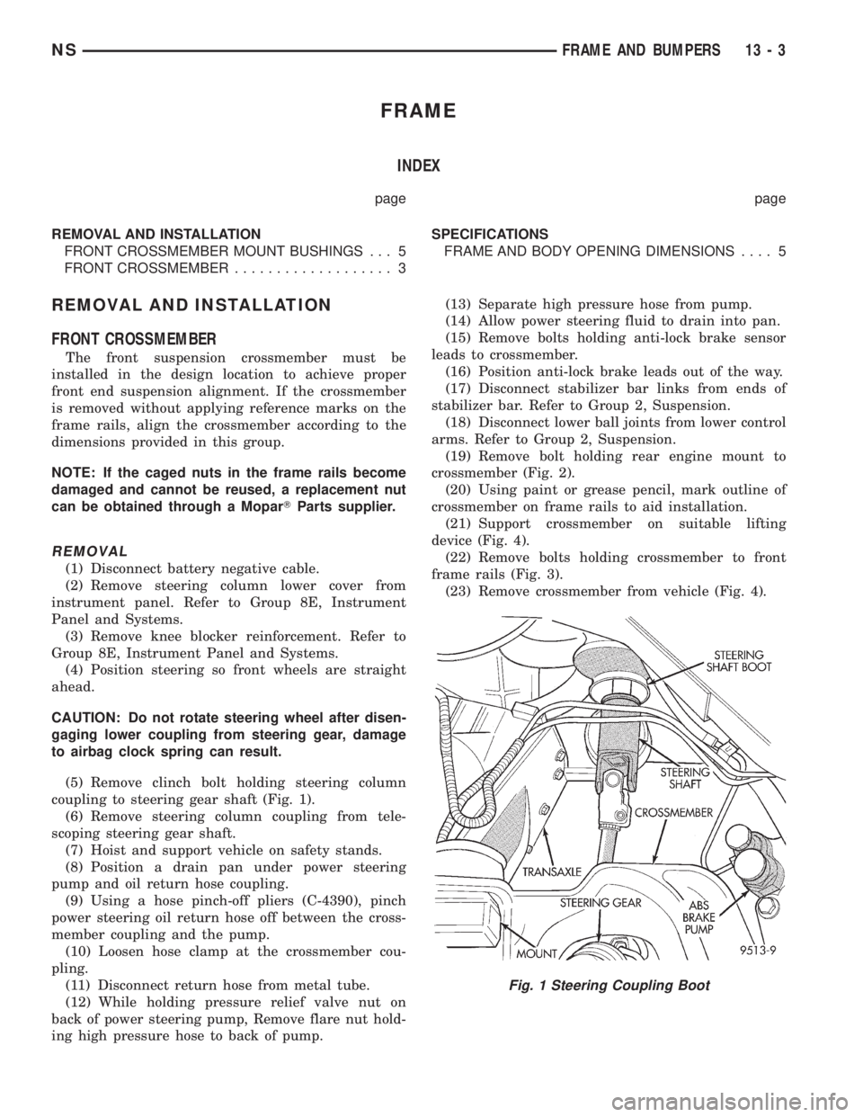
(5) Remove clinch bolt holding steering column
coupling to steering gear shaft (Fig. 1).
(6) Remove steering column coupling from tele-
scoping steering gear shaft.
(7) Hoist and support vehicle on safety stands.
(8) Position a drain pan under power steering
pump and oil return hose coupling.
(9) Using a hose pinch-off pliers (C-4390), pinch
power steering oil return hose off between the cross-
member coupling and the pump.
(10) Loosen hose clamp at the crossmember cou-
pling.
(11) Disconnect return hose from metal tube.
(12) While holding pressure relief valve nut on
back of power steering pump, Remove flare nut hold-
ing high pressure hose to back of pump.(13) Separate high pressure hose from pump.
(14) Allow power steering fluid to drain into pan.
(15) Remove bolts holding anti-lock brake sensor
leads to crossmember.
(16) Position anti-lock brake leads out of the way.
(17) Disconnect stabilizer bar links from ends of
stabilizer bar. Refer to Group 2, Suspension.
(18) Disconnect lower ball joints from lower control
arms. Refer to Group 2, Suspension.
(19) Remove bolt holding rear engine mount to
crossmember (Fig. 2).
(20) Using paint or grease pencil, mark outline of
crossmember on frame rails to aid installation.
(21) Support crossmember on suitable lifting
device (Fig. 4).
(22) Remove bolts holding crossmember to front
frame rails (Fig. 3).
(23) Remove crossmember from vehicle (Fig. 4).
Fig. 1 Steering Coupling Boot
NSFRAME AND BUMPERS 13 - 3
Page 1285 of 1938
(7) Connect lower ball joints to lower control arms.
Refer to Group 2, Suspension.
(8) Connect stabilizer bar links to ends of stabi-
lizer bar. Refer to Group 2, Suspension.
(9) Install bolts to hold anti-lock brake sensor
leads to crossmember.
(10) Install high pressure hose to pump.
(11) Connect return hose to metal tube.
(12) Tighten hose clamp at the crossmember cou-
pling.
(13) Remove pinch-off pliers.
(14) Position steering so front wheels are straight
ahead.
(15) Install steering column coupling to telescoping
steering gear shaft.
(16) Install clinch bolt to hold steering column cou-
pling to steering gear shaft.
(17) Install knee blocker reinforcement. Refer to
Group 8E, Instrument Panel and Systems.
(18) Install steering column lower cover from
instrument panel. Refer to Group 8E, Instrument
Panel and Systems.
(19) Connect battery negative cable.
FRONT CROSSMEMBER MOUNT BUSHINGS
REMOVAL
(1) Using paint or grease pencil, mark outline of
crossmember on frame rails.
(2) Loosen bolts holding crossmember to frame
rails.
(3) Remove bolt on bushing that requires replace-
ment.
(4) Allow crossmember to drop down enough to
gain clearance for bushing removal.
(5) Remove bushing from vehicle.
INSTALLATION
(1) Apply rubber lube or soap to replacement bush-
ing.(2) Insert lower half of bushing into square hole in
crossmember.
(3) Place upper half of bushing on top of cross-
member aligned to receive square tube protruding
upward from lower bushing half.
(4) Squeeze bushing halves together to ensure they
are properly mated.
(5) Lift crossmember upward to close gap between
the bushing and frame.
(6) Verify that lower bushing is fully seated into
crossmember and upper bushing.
(7) Install bolt to hold bushing and crossmember
to frame rail hand tight.
(8) Align crossmember to reference marks on
frame rails.
(9) Tighten crossmember to frame rails attaching
bolts to 163 N´m (120 ft. lbs.) torque.
SPECIFICATIONS
FRAME AND BODY OPENING DIMENSIONS
Frame dimensions are listed in metric scale. All
dimensions are from center to center of Principal
Locating Point (PLP), or from center to center of PLP
and fastener location.
VEHICLE PREPARATION
Position the vehicle on a frame alignment rack,
refer to instructions provided with equipment being
used. Adjust the vehicle PLP heights to the specified
dimension above the work surface (datum line). Ver-
tical dimensions can be taken from the datum line to
the locations indicated were applicable. Refer to (Fig.
5), (Fig. 6), (Fig. 7), (Fig. 8), (Fig. 9), (Fig. 10) and
(Fig. 11) for proper dimensions.
NSFRAME AND BUMPERS 13 - 5
REMOVAL AND INSTALLATION (Continued)
Page 1298 of 1938
FUEL DELIVERY SYSTEM
INDEX
page page
DESCRIPTION AND OPERATION
FUEL DELIVERY SYSTEM.................. 4
FUEL INJECTORS........................ 5
FUEL LEVEL SENSOR..................... 5
FUEL PRESSURE REGULATOR.............. 5
FUEL PUMP MODULE..................... 4
FUEL TANK............................. 5
PRESSURE-VACUUM FILLER CAP........... 6
QUICK-CONNECT FITTINGS................ 6
DIAGNOSIS AND TESTING
FUEL INJECTORS........................ 9
FUEL LEVEL SENSOR..................... 9
FUEL PUMP PRESSURE TEST 2.4/3.3/3.8L..... 6
SERVICE PROCEDURES
FUEL SYSTEM PRESSURE RELEASE
PROCEDUREÐ2.4/3.3/3.8L............... 11
FUEL SYSTEM PRESSURE RELEASE
PROCEDUREÐ3.0L ENGINE............. 11
HOSES AND CLAMPS.................... 12QUICK-CONNECT FITTINGS............... 12
REMOVAL AND INSTALLATION
ACCELERATOR PEDAL................... 26
FUEL FILTER........................... 12
FUEL INJECTOR RAILÐ2.4L............... 18
FUEL INJECTOR RAILÐ3.0L............... 19
FUEL INJECTOR RAILÐ3.3/3.8L............ 21
FUEL INJECTORSÐ3.0L.................. 25
FUEL INJECTORÐ2.4L................... 24
FUEL INJECTORÐ3.3/3.8L................. 26
FUEL LEVEL SENSOR.................... 15
FUEL PRESSURE REGULATOR............. 14
FUEL PUMP INLET STRAINER............. 15
FUEL PUMP MODULE.................... 13
FUEL TANK............................ 17
THROTTLE CABLE...................... 27
SPECIFICATIONS
FUEL TANK CAPACITY................... 28
TORQUE.............................. 28
DESCRIPTION AND OPERATION
FUEL DELIVERY SYSTEM
The front wheel drive van uses a plastic fuel tank
located on the left side of the vehicle.
The Fuel Delivery System consists of: the electric
fuel pump module, fuel filter, tubes/lines/hoses, fuel
rail, and fuel injectors.
The in-tank fuel pump module contains the fuel
pump and pressure regulator. The pump is serviced
as part of the fuel pump module. Refer to Fuel Pump
Module.
The fuel filter is a replaceable in-line filter. The fil-
ter attaches to a bracket mounted on top of the fuel
tank. Refer to the Maintenance Schedules in the
Introduction section of this manual for recommended
fuel filter replacement intervals.
A returnless fuel system is used on all vehicles.
Fuel is returned through the fuel pump module and
back to the fuel tank. A separate fuel return line
from the tank to the engine is no longer used.
FUEL PUMP MODULE
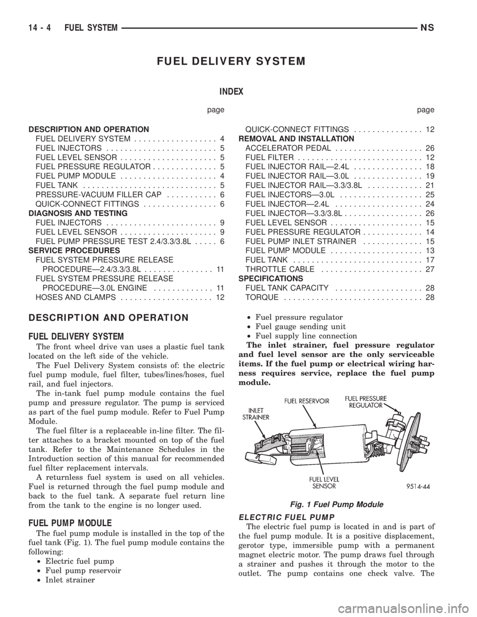
The fuel pump module is installed in the top of the
fuel tank (Fig. 1). The fuel pump module contains the
following:
²Electric fuel pump
²Fuel pump reservoir
²Inlet strainer²Fuel pressure regulator
²Fuel gauge sending unit
²Fuel supply line connection
The inlet strainer, fuel pressure regulator
and fuel level sensor are the only serviceable
items. If the fuel pump or electrical wiring har-
ness requires service, replace the fuel pump
module.
ELECTRIC FUEL PUMP
The electric fuel pump is located in and is part of
the fuel pump module. It is a positive displacement,
gerotor type, immersible pump with a permanent
magnet electric motor. The pump draws fuel through
a strainer and pushes it through the motor to the
outlet. The pump contains one check valve. The
Fig. 1 Fuel Pump Module
14 - 4 FUEL SYSTEMNS
Page 1299 of 1938
check valve, in the pump outlet, maintains pump
pressure during engine off conditions. The fuel pump
relay provides voltage to the fuel pump.
The fuel pump has a maximum deadheaded pres-
sure output of approximately 635 kPa (95 psi). The
regulator adjusts fuel system pressure to approxi-
mately 338 kPa (49 psi).
FUEL PUMP ELECTRICAL CONTROL
Voltage to operate the electric pump is supplied
through the fuel pump relay. For an electrical opera-
tional description of the fuel pump refer to fuel Pump
RelayÐPCM Output.
ELECTRICAL PUMP REPLACEMENT
The electric fuel pump is not serviceable. If the
fuel pump or electrical wiring harness needs replace-
ment, the complete fuel pump module must be
replaced. Perform the Fuel System Pressure Release
procedure before servicing the fuel pump.
FUEL LEVEL SENSOR
The level sensor is attached to the side of the fuel
pump module. The level sensor consists of a float, an
arm, and a variable resistor. As the fuel level
increases, the float and arm move up. This decreases
the sending unit resistance, causing the fuel gauge
on the instrument panel to read full.
FUEL PRESSURE REGULATOR
The fuel system uses a nonadjustable pressure reg-
ulator that maintains fuel system pressure at
approximately 338 kPa (49 psi), 3.3l uses approxi-
mately 379 kPa (55 psi). The fuel pressure regulator
contains a diaphragm, calibrated spring and a fuel
return valve. The spring pushes down on the dia-
phragm and closes off the fuel return port. System
fuel pressure reflects the amount of fuel pressure
required to open the return port.
The pressure regulator is a mechanical device that
is NOT controlled by the PCM or engine vacuum.
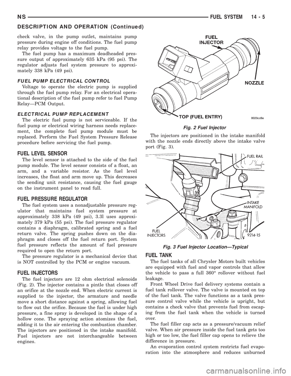
FUEL INJECTORS
The fuel injectors are 12 ohm electrical solenoids
(Fig. 2). The injector contains a pintle that closes off
an orifice at the nozzle end. When electric current is
supplied to the injector, the armature and needle
move a short distance against a spring, allowing fuel
to flow out the orifice. Because the fuel is under high
pressure, a fine spray is developed in the shape of a
hollow cone. The spraying action atomizes the fuel,
adding it to the air entering the combustion chamber.
The injectors are positioned in the intake manifold.
Fuel injectors are not interchangeable between
engines.The injectors are positioned in the intake manifold
with the nozzle ends directly above the intake valve
port (Fig. 3).
FUEL TANK
The fuel tanks of all Chrysler Motors built vehicles
are equipped with fuel and vapor controls that allow
the vehicle to pass a full 360É rollover without fuel
leakage.
Front Wheel Drive fuel delivery systems contain a
fuel tank rollover valve. The valve is mounted on top
of the fuel tank. The valve functions as a tank pres-
sure control valve while the vehicle is upright, but
contains a check valve that prevents fuel from escap-
ing from the fuel tank when the vehicle is turned
over.
The fuel filler cap acts as a pressure/vacuum relief
valve. When air pressure inside the fuel tank gets too
high or too low, the fuel filler cap opens to relieve the
difference in pressure.
An evaporation control system restricts fuel evapo-
ration into the atmosphere and reduces unburned
Fig. 2 Fuel Injector
Fig. 3 Fuel Injector LocationÐTypical
NSFUEL SYSTEM 14 - 5
DESCRIPTION AND OPERATION (Continued)
Page 1303 of 1938
FUEL LEVEL SENSOR
This procedure tests the resistance of the level sen-
sor itself. It does not test the level sensor circuit.
Refer to Group 8W - Wiring Diagrams for circuit
identification.
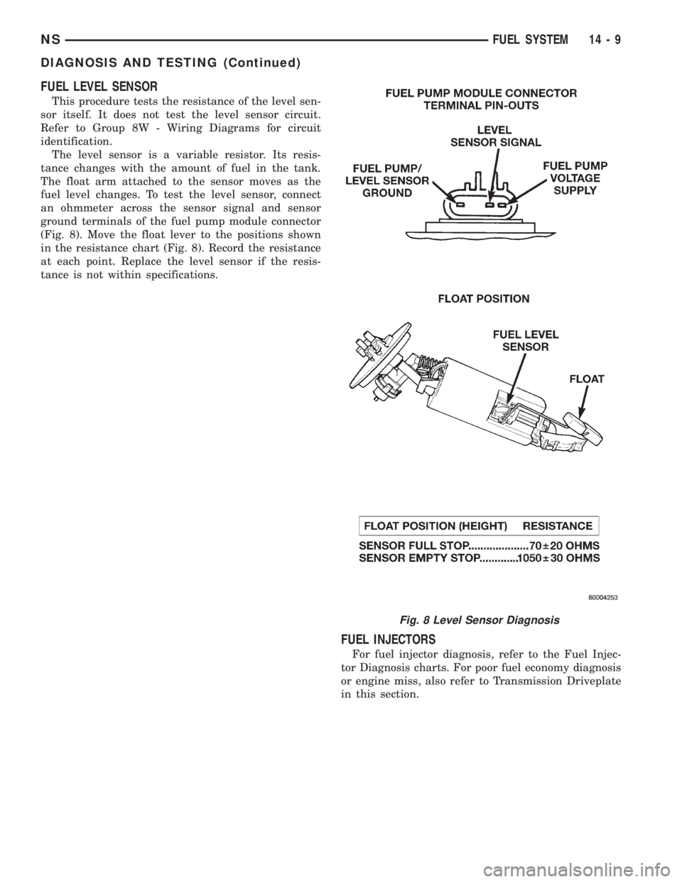
The level sensor is a variable resistor. Its resis-
tance changes with the amount of fuel in the tank.
The float arm attached to the sensor moves as the
fuel level changes. To test the level sensor, connect
an ohmmeter across the sensor signal and sensor
ground terminals of the fuel pump module connector
(Fig. 8). Move the float lever to the positions shown
in the resistance chart (Fig. 8). Record the resistance
at each point. Replace the level sensor if the resis-
tance is not within specifications.
FUEL INJECTORS
For fuel injector diagnosis, refer to the Fuel Injec-
tor Diagnosis charts. For poor fuel economy diagnosis
or engine miss, also refer to Transmission Driveplate
in this section.
Fig. 8 Level Sensor Diagnosis
NSFUEL SYSTEM 14 - 9
DIAGNOSIS AND TESTING (Continued)
Page 1309 of 1938
(3) Fold tangs on regulator retainer over tabs on
housing.
FUEL PUMP INLET STRAINER
REMOVAL
(1) Remove fuel pump module. Refer to Fuel Pump
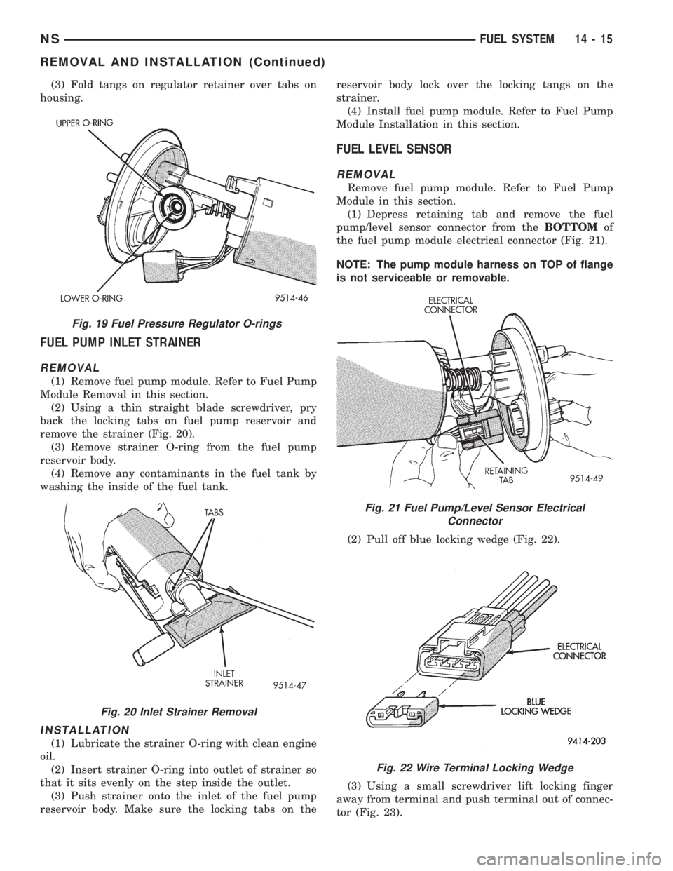
Module Removal in this section.
(2) Using a thin straight blade screwdriver, pry
back the locking tabs on fuel pump reservoir and
remove the strainer (Fig. 20).
(3) Remove strainer O-ring from the fuel pump
reservoir body.
(4) Remove any contaminants in the fuel tank by
washing the inside of the fuel tank.
INSTALLATION
(1) Lubricate the strainer O-ring with clean engine
oil.
(2) Insert strainer O-ring into outlet of strainer so
that it sits evenly on the step inside the outlet.
(3) Push strainer onto the inlet of the fuel pump
reservoir body. Make sure the locking tabs on thereservoir body lock over the locking tangs on the
strainer.
(4) Install fuel pump module. Refer to Fuel Pump
Module Installation in this section.
FUEL LEVEL SENSOR
REMOVAL
Remove fuel pump module. Refer to Fuel Pump
Module in this section.
(1) Depress retaining tab and remove the fuel
pump/level sensor connector from theBOTTOMof
the fuel pump module electrical connector (Fig. 21).
NOTE: The pump module harness on TOP of flange
is not serviceable or removable.
(2) Pull off blue locking wedge (Fig. 22).
(3) Using a small screwdriver lift locking finger
away from terminal and push terminal out of connec-
tor (Fig. 23).
Fig. 19 Fuel Pressure Regulator O-rings
Fig. 20 Inlet Strainer Removal
Fig. 21 Fuel Pump/Level Sensor Electrical
Connector
Fig. 22 Wire Terminal Locking Wedge
NSFUEL SYSTEM 14 - 15
REMOVAL AND INSTALLATION (Continued)