1996 CHRYSLER VOYAGER wiring
[x] Cancel search: wiringPage 1784 of 1938
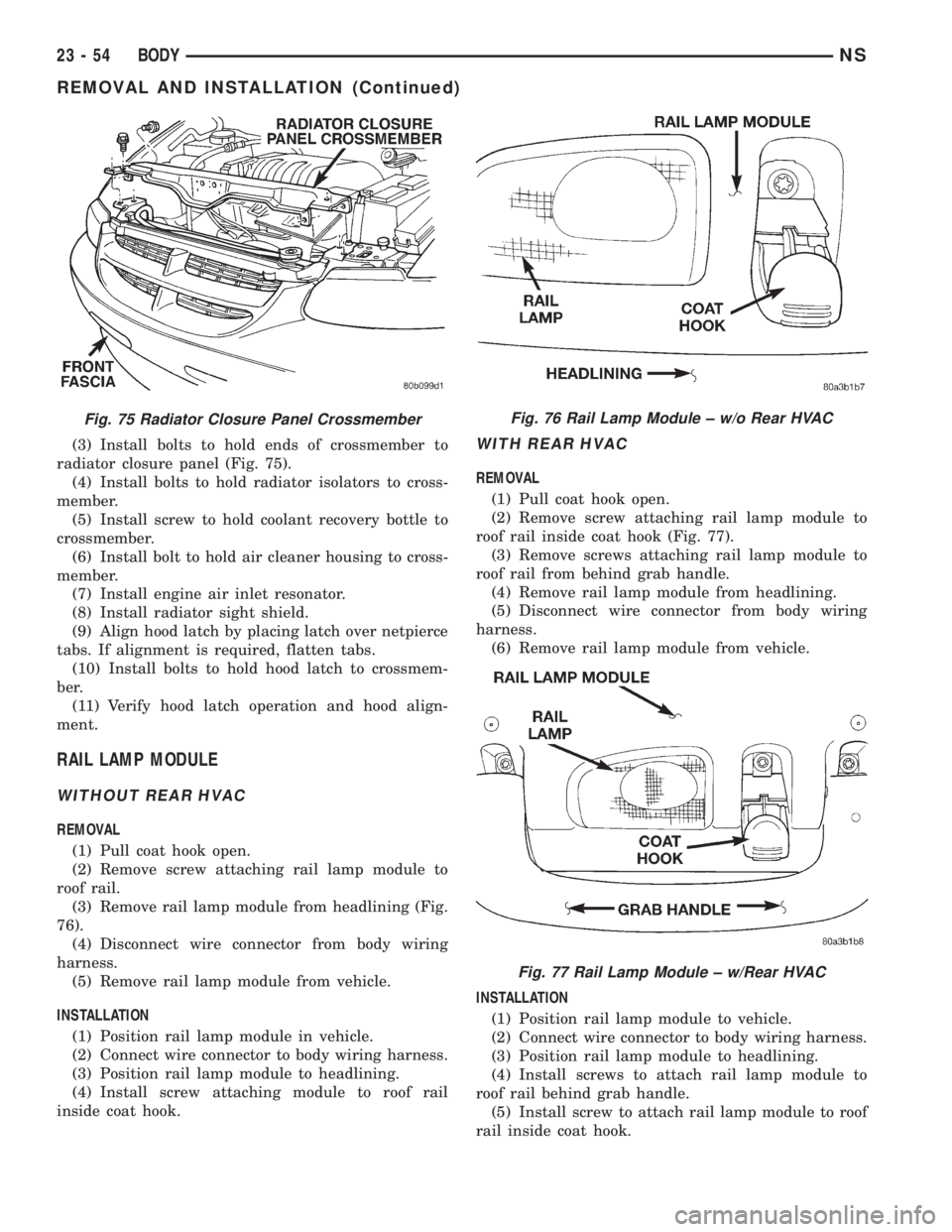
(3) Install bolts to hold ends of crossmember to
radiator closure panel (Fig. 75).
(4) Install bolts to hold radiator isolators to cross-
member.
(5) Install screw to hold coolant recovery bottle to
crossmember.
(6) Install bolt to hold air cleaner housing to cross-
member.
(7) Install engine air inlet resonator.
(8) Install radiator sight shield.
(9) Align hood latch by placing latch over netpierce
tabs. If alignment is required, flatten tabs.
(10) Install bolts to hold hood latch to crossmem-
ber.
(11) Verify hood latch operation and hood align-
ment.
RAIL LAMP MODULE
WITHOUT REAR HVAC
REMOVAL
(1) Pull coat hook open.
(2) Remove screw attaching rail lamp module to
roof rail.
(3) Remove rail lamp module from headlining (Fig.
76).
(4) Disconnect wire connector from body wiring
harness.
(5) Remove rail lamp module from vehicle.
INSTALLATION
(1) Position rail lamp module in vehicle.
(2) Connect wire connector to body wiring harness.
(3) Position rail lamp module to headlining.
(4) Install screw attaching module to roof rail
inside coat hook.
WITH REAR HVAC
REMOVAL
(1) Pull coat hook open.
(2) Remove screw attaching rail lamp module to
roof rail inside coat hook (Fig. 77).
(3) Remove screws attaching rail lamp module to
roof rail from behind grab handle.
(4) Remove rail lamp module from headlining.
(5) Disconnect wire connector from body wiring
harness.
(6) Remove rail lamp module from vehicle.
INSTALLATION
(1) Position rail lamp module to vehicle.
(2) Connect wire connector to body wiring harness.
(3) Position rail lamp module to headlining.
(4) Install screws to attach rail lamp module to
roof rail behind grab handle.
(5) Install screw to attach rail lamp module to roof
rail inside coat hook.
Fig. 75 Radiator Closure Panel CrossmemberFig. 76 Rail Lamp Module ± w/o Rear HVAC
Fig. 77 Rail Lamp Module ± w/Rear HVAC
23 - 54 BODYNS
REMOVAL AND INSTALLATION (Continued)
Page 1822 of 1938

CAUTION: The refrigerant oil used in a R-134a A/C
system is unique. Use only oils which were
designed to work with R-134a refrigerant. The oil
designated for this vehicle is ND8 PAG (polyalka-
lene glycol).
SERVICING REFRIGERANT OIL LEVEL
(1) Using a refrigerant recovery machine, remove
refrigerant from the A/C system.
(2) Remove refrigerant lines from A/C compressor.
(3) Remove compressor from vehicle.
(4) From suction port on top of compressor, drain
refrigerant oil from compressor.
(5) Add system capacity minus the capacity of
components that have not been replaced through suc-
tion port on compressor. Refer to the Refrigerant Oil
Capacity Chart.
(6) Install compressor, connect refrigerant lines,
evacuate, and charge refrigerant system.
DIAGNOSIS AND TESTING
ACTUATOR CALIBRATION/DIAGNOSTICS AND
COOLDOWN TEST
GENERAL INFORMATION
If the HVAC control module is replaced, the Cali-
bration Diagnostic and Cooldown tests will need to
be performed. Once this group of tests have success-
fully passed, they can be performed individually. The
engine must be running during the test to provide
hot coolant for the heater, A/C compressor operation
and to assure that the actuators are calibrated cor-
rectly. The HVAC control module is capable of trou-
bleshooting the system in approximately 120 seconds.
If a condition is detected, an error code is displayed.
The error code cannot be erased until the condition is
repaired and the diagnostic test is performed. Check
wire before replacing components, refer to Group 8W,
Wiring Diagrams.CAUTION: Do not remove the actuators from the
Heater-A/C unit assembly with power applied.
Removal should only be done with the Ignition OFF.
The actuators have no mechanical stops to limit the
travel. If the actuator rotates and is not connected
to the unit assembly, it will become out of calibra-
tion.
ACTUATOR CALIBRATION
Mode, Blend and Zone (if equipped) door calibra-
tion compensates for mechanical variations in the
actuators, HVAC control module and its linkages. In-
vehicle calibration can be entered from the control's
front panel. If the REAR WIPE and INTERMIT-
TENT LED's flash simultaneously when Ignition is
cycled ON, the actuators have not been calibrated or
during the previous calibration a failure occurred
(Fig. 6) and (Fig. 7). Diagnostics will always occur
during Calibration Diagnostic and Cooldown test.
REFRIGERANT OIL CAPACITIES
Refrigerant
Oil Capaci-
tiesFront A/C Dual A/C
Component ml oz ml oz
Compressor 150 ml 5.0 oz 220 ml 7.4 oz
Filter-Drier 30 ml 1.0 oz 30 ml 1.0 oz
Condenser 30 ml 1.0 oz 30 ml 1.0 oz
Evaporator 60 ml 2.0 oz 60 ml 2 .0 oz
Rear Evap. N/A N/A 60 ml 2.0 oz
Fig. 6 Radio Bezel and HVAC Control
24 - 6 HEATING AND AIR CONDITIONINGNS
DESCRIPTION AND OPERATION (Continued)
Page 1825 of 1938
FAIL CODES/LEVEL DISPLAY
Fail Codes/Level are displayed using the REAR
WIPER and INTERMITTENT LED's flashing in the
sequence indicated below. The REAR WIPER LED
represents the Level and the INTERMITTENT LED
represents the Value. After Calibration/Diagnostics is
completed, the control will begin flashing Level 1
codes. Depressing the WASH button will cycle to
Level 2, depressing WASH again will cycle to Level 3.
Each time the WASH button is depressed will cycle
to the next level. After Level 5 is reached, you will
cycle back to Level 1. If the Control is a Heater Only
you will only cycle from Levels 1 to 3.
TEMPERATURE AND MODE POTENTIOMETER
DIAGNOSTICS
The Temperature and Mode Potentiometer can be
tested after calibration is complete by pressing the
WASH button and cycling to Levels 2, 3 or 5 as dis-
played by the REAR WIPER LED. On Heater Only
units you can only cycle to Levels 2 and 3. In eachindividual test the INTERMITTENT LED flash rate
will change as the Temperature or Mode potentiome-
ter is moved from one end to the other, see Potenti-
ometer vs. Position and Flash Rate table.
EVAPORATOR PROBE TEMPERATURE
DIAGNOSTICS
The evaporator probe can be tested by using the
INTERMITTENT LED to display the actual temper-
ature the sensor is reading. The HVAC control mod-
ule can only display temperatures from 1 to 99
degrees. To read the temperature, perform the follow-
ing:
²Set Blower motor to any speed other than OFF
²Set A/C to ON, if A/C Clutch does not engage
make sure Fail Codes 5 and 6 are cleared.To clear
the error code 5 and 6 the evaporator probe and/or
the wiring repair needs to be completed. Then, press
and hold the intermittent wipe button for 5 seconds.
²Run Diagnostics (Depress REAR WIPER and
REAR WASH)
²When Diagnostics is complete, Cycle to Level 4.
Display Sequence is as follows:
²REAR WIPER LED will display the Level
²INTERMITTENT LED will display ten's digit
²Short Pause
²INTERMITTENT LED will display the one's
digit.
The HVAC control module will continue to cycle
the Level and then Temperature until the level is
changed or Calibration Diagnostics and Cooldown
test is exited.
HVAC CONTROL DIAGNOSTIC CONDITIONS
For wiring circuits, wiring connectors, and Pin
numbers, refer to Group 8W, Wiring Diagrams.
After calibration, Rear Wiper LED flashing
once, Intermittent LED not flashing.
The system has passed calibration. Press the Rear
Wiper button to exit calibration.
WIPE BUTTON LED
LEVEL DISPLAY
1 FAIL CODES
2 MODE POTENTIOMETER TEST
3 BLEND/PASS. POTENTIOMETER TEST
4 EVAPORATOR PROBE (A/C AND ZONE
UNITS ONLY)
5 DRIVER POTENTIOMETER (ZONE UNITS
ONLY)
LEVEL 1±FAILURE CODE VALUES
(INTERMITTENT WIPE BUTTON LED)
CODE DEFINITION
0 PASSED ALL TESTS
1 MODE ACTUATOR DID NOT REACH
DEFROST POSITION
2 MODE ACTUATOR DID NOT REACH
PANEL POSITION
3 BLEND/PASS. ACTUATOR DID NOT
REACH COLD STOP
4 BLEND PASS. ACTUATOR DID NOT
REACH HEAT STOP
5 EVAPORATOR PROBE OPEN
6 EVAPORATOR PROBE SHORTED
7 DRIVER ACTUATOR DID NOT REACH
COLD STOP
8 ZONE/DRIVER ACTUATOR DID NOT
REACH HEAT STOP
9 CONTROL HEAD INTERNAL FAILURE
POTENTIOMETER VS. POSITION AND FLASH
RATE
POTENTIOM-
ETERINTERMIT-
TENT LED
FASTER
FLASH RATEINTERMITTENT
LED SLOWER
FLASH RATE
MODE PANEL DEFROST
BLEND/PASS. HOT COLD
DRIVER HOT COLD
NSHEATING AND AIR CONDITIONING 24 - 9
DIAGNOSIS AND TESTING (Continued)
Page 1826 of 1938
After calibration, Rear Wiper LED flashing
once, Intermittent LED flashing once. The
mode actuator did not reach defrost position.
(1) Using a voltmeter, check the mode door actua-
tor wiring connector. Check Pin 1 for battery voltage.
Move the HVAC control from the defrost to panel
position, and check Pin 6 voltage it should change
from 0.5 - 1 volts to 3.5 - 4.5 volts. If voltage is OK,
go to Step 2. If not OK, check for loose or corroded
connector, open or shorted circuit and repair as nec-
essary.
(2) Remove actuator, and check if the gear pins are
in the correct track on cam or if they are binding. If
OK, go to Step 3. If not OK, repair as necessary.
(3) Check for binding door, if door is binding repair
as necessary. If gears and door are OK, replace
actuator.
(4) Once repairs are completed repeat the Calibra-
tion Diagnostic and Cooldown test. Repeating the
test is necessary to clear the fault codes.
After calibration, Rear Wiper LED flashing
once, Intermittent LED flashing twice. The
mode actuator did not reach panel position.
(1) Using a voltmeter, check the mode door actua-
tor wiring connector. Check Pin 1 for battery voltage.
Move the HVAC control from panel to defrost posi-
tion, and check Pin 6 voltage it should change from
3.5 - 4.5 volts to 0.5 - 1 volts. If voltage is OK, go to
Step 2. If not OK, check for loose or corroded connec-
tor, open or shorted circuit and repair as necessary.
(2) Remove actuator, and check if the gear pins are
in the correct cam track or binding. If OK, go to Step
3. If not OK, repair as necessary.
(3) Check for binding door, if door is binding repair
as necessary. If gears and door are OK, replace
actuator.
(4) Once repairs are completed repeat the Calibra-
tion Diagnostic and Cooldown test. Repeating the
test is necessary to clear the fault codes.
After calibration, Rear Wiper LED flashing
once, Intermittent LED flashing three times.
The main temperature actuator/passenger
temperature actuator on a zone system did
not reach cold stop.
(1) Check if the correct HVAC control module was
used.
(2) Using a voltmeter, check the temperature door
actuator wiring connector. Check Pin 1 for battery
voltage. Move the HVAC control from the cold to hot
position, and check Pin 5 voltage it should change
from 0.5 - 4 volts to 3.5 - 4.5 volts. If voltage is OK,
go to Step 3. If not OK, check for loose or corroded
connector, open or shorted circuit and repair as nec-
essary.(3) Remove actuator, and check if gear pins are in
the correct cam track or binding. If OK, go to Step 4.
If not OK, repair as necessary.
(4) Check for binding door, if door is binding repair
as necessary. If gears and door are OK, replace
actuator.
(5) Once repairs are completed repeat the Calibra-
tion Diagnostic and Cooldown test. Repeating the
test is necessary to clear the fault codes.
After calibration, Rear Wiper LED flashing
once, Intermittent LED flashing four times.
The main temperature actuator/passenger
temperature actuator on a zone system did
not reach hot stop.
(1) Check if the correct HVAC control module was
used.
(2) Using a voltmeter, check the temperature door
actuator wiring connector. Check Pin 1 for battery
voltage. Move the HVAC control from hot to cold
position and check Pin 5 voltage it should change
from 3.5 -4.5 volts 0.5 - 1.5 volts. If voltage is OK, go
to Step 3. If not OK, check for loose or corroded con-
nector, open or shorted circuit and repair as neces-
sary.
(3) Remove actuator, and check if the gear pins are
in the correct track on cam or if they are binding. If
OK, go to Step 4. If not OK, repair as necessary.
(4) Check for binding door, if door is binding repair
as necessary. If gears and door are OK, replace
actuator.
(5) Once repairs are completed repeat the Calibra-
tion Diagnostic and Cooldown test. Repeating the
test is necessary to clear the fault codes.
After calibration, Rear Wiper LED flashing
once, Intermittent LED flashing five times.
The evaporator probe is open.
(1) Using a voltmeter, check Pin 1 of the evapora-
tor probe wiring connector for 0.1 - 4.75 volts. If OK,
go to Step 2. If not OK, if greater than 4.75 volts
check for loose or corroded connector, open circuit
and repair as necessary.
(2) Using a ohmmeter, check Pin 2 for a good
ground, If OK, go to Step 3. If not OK, check for loose
or corroded connector, open or shorted circuit and
repair as necessary.
(3) If ground and power circuit are OK, replace
Evaporator Probe.
(4) Once repairs are completed, press the intermit-
tent button about 5 seconds until all LED's light to
remove fault code from memory. Then repeat the Cal-
ibration Diagnostic and Cooldown test. Repeating the
test is necessary to clear the fault codes.
24 - 10 HEATING AND AIR CONDITIONINGNS
DIAGNOSIS AND TESTING (Continued)
Page 1827 of 1938

After calibration, Rear Wiper LED flashing
once, Intermittent LED flashing six times. The
evaporator probe is shorted.
(1) Using a voltmeter, check Pin 1 of the evapora-
tor probe wiring connector for 0.1 - 4.75 volts. If OK,
go to Step 2. If less than 0.1 volts, check for loose or
corroded connector, open or shorted circuit and repair
as necessary.
(2) Using a ohmmeter, check Pin 2 for a good
ground, If OK, go to Step 3. If not OK, check for
shorted circuit and repair as necessary.
(3) If ground and power circuit are OK, replace
Evaporator Probe
(4) Once repairs are completed, press the intermit-
tent button about 5 seconds until all LED's light to
remove fault code from memory. Then repeat the Cal-
ibration Diagnostic and Cooldown test. Repeating the
test is necessary to clear the fault codes.
After calibration, Rear Wiper LED flashing
once, Intermittent LED flashing seven times.
The Driver's temperature actuator on a zone
system did not reach cold stop.
(1) Check if the correct HVAC control module was
used.
(2) Using a voltmeter, check at the temperature
door actuator wiring connector, check Pin 1 for bat-
tery voltage. Move the HVAC control from cold to the
hot position, check Pin 4 voltage it should change
from 0.5 - 1.5 volts 3.5 - 4.5 volts. If voltage is OK, go
to Step 3. If not OK, check for loose or corroded con-
nector, open or shorted circuit and repair as neces-
sary.
(3) Remove actuator, and check if the gear pins are
in the correct track on cam or if they are binding. If
OK, go to Step 4. If not OK, repair as necessary.
(4) Check for binding doors, if door are binding
repair as necessary. If gears and door are OK, replace
actuator.
(5) Once repairs are completed repeat the Calibra-
tion Diagnostic and Cooldown test. Repeating the
test is necessary to clear the fault codes.
After calibration, Rear Wiper LED flashing
once, Intermittent LED flashing eight times.
The Driver's temperature actuator on a zone
system did not reach hot stop.
(1) Check if the correct HVAC control module was
used.
(2) Using a voltmeter, check at the temperature
door actuator wiring connector, check Pin 1 for bat-
tery voltage. Move the HVAC control from hot to cold
position, Pin 4 voltage it should change from 3.5 - 4.5
volts to 0.5 - 1.5 volts. If voltage is OK, go to Step 3.
If not OK, check for loose or corroded connector, open
or shorted circuit and repair as necessary.(3) Remove actuator, and check if the gear pins are
in the correct track on cam or if they are binding. If
OK, go to Step 4. If not OK, repair as necessary.
(4) Check for binding door, if door is binding repair
as necessary. If gears and door are OK, replace
actuator.
(5) Once repairs are completed repeat the Calibra-
tion Diagnostic and Cooldown test. Repeating the
test is necessary to clear the fault codes.
After calibration, Rear Wiper LED flashing
once, Intermittent LED flashing nine times.
The HVAC control module, has a internal
failure.
(1) Replace the HVAC control module.
(2) Once repairs are completed repeat the Calibra-
tion Diagnostic and Cooldown test. Repeating the
test is necessary to clear the fault codes.
After calibration and testing the A/C and
RECIRC LED flashing simultaneously. Failed
Cooldown test.
(1) Determine if the refrigerant system is operat-
ing correctly:
²Check the outlet air temperature
²Feel the compressor suction plumbing, is it hot?
(2) If not OK, go to Step 3. If OK, repeat the Cal-
ibration Diagnostic and Cooldown test.
(3) If system does not seem to be operating cor-
rectly, perform diagnostics for poor performance:
²Low refrigerant charge
²No charge
²Compressor not operating
Verify that the test was done with the evaporator
at room temperature. The test consists of starting
the compressor and measuring the time it takes for
the evaporator temperature to fall 7ÉC (20ÉF). If the
compressor has been running, the evaporator is cold
already and will not be capable of falling 7ÉC (20ÉF).
If the test was run with a cold evaporator, turn A/C
off and turn the blower motor switch to high position
for 3 to 5 minutes till the evaporator is to room tem-
perature. Then repeat the Calibration Diagnostic and
Cooldown test.
If refrigerant system is performing properly and
the system will not pass test. Repeat the Calibration
Diagnostic and Cooldown test to determine if the
evaporator temperature FIN sensor has developed an
open or a short circuit. If the HVAC control module
still passes Calibration test, verify Cooldown test
manually with a pocket thermometer. The outlet air
temperature must drop at least 7ÉC (20ÉF) within
two minutes. If the vehicle passes with the manual
thermometer, take HVAC control to level 4 (evapora-
tor probe temperature readout) and repeat the
Cooldown test. Ensure the evaporator is at room tem-
perature before starting test. Check if evaporator
NSHEATING AND AIR CONDITIONING 24 - 11
DIAGNOSIS AND TESTING (Continued)
Page 1829 of 1938
BLOWER MOTOR AND WHEEL ASSEMBLY
VIBRATION AND/OR NOISE DIAGNOSIS
The blower speed switch, in conjunction with the
resistor block, supplies the blower motor with varied
voltage.
CAUTION: Stay clear of the blower motor and resis-
tor block (Hot). Do not operate the blower motor
with the resistor block removed from the heater A/C
housing.
Refer to the Blower Motor Vibration/Noise chart in
this section for diagnosis.
COMPRESSOR NOISE DIAGNOSIS
Excessive noise while the A/C is being used, can be
caused by loose mounts, loose clutch, or high operat-
ing pressure. Verify compressor drive belt condition,
proper refrigerant charge and head pressure before
compressor repair is performed.
If the A/C drive belt slips at initial start-up, it does
not necessarily mean the compressor has failed.
With the close tolerances of a compressor it is pos-
sible to experience a temporary lockup. The longer
the A/C system is inactive, the more likely the condi-
tion to occur.
This condition is the result of normal refrigerant
movement within the A/C system caused by temper-
ature changes. The refrigerant movement may wash
the oil out of the compressor.
COMPRESSOR CLUTCH/COIL
The air conditioning compressor clutch electrical
circuit is controlled by the Powertrain Control Mod-
ule. It is located in the engine compartment outboard
of the battery.If the compressor clutch does not engage verify
refrigerant charge.
If the compressor clutch still does not engage check
for battery voltage at the pressure transducer located
on the liquid line. If voltage is not detected, refer to:
²Group 8W, Wiring diagrams.
²Powertrain Diagnostic Procedures manual for
diagnostic information.
If voltage is detected at the pressure transducer,
connect pressure transducer and check for battery
voltage between the compressor clutch connector ter-
minals.
If voltage is detected, perform A/C Clutch Coil
Tests.
TESTS
(1) Verify battery state of charge. (Test indicator in
battery should be green).
(2) Connect an ampmeter (0-10 ampere scale) in
series with the clutch coil terminal. Use a voltmeter
(0-20 volt scale) with clip leads measuring voltage
across the battery and A/C clutch.
(3) With A/C control in A/C mode and blower at
low speed, start the engine and run at normal idle.
(4) The A/C clutch should engage immediately and
the clutch voltage should be within two volts of the
battery voltage. If the A/C clutch does not engage,
test the fuse.
(5) The A/C clutch coil is acceptable if the current
draw is 2.0 to 3.7 amperes at 11.5-12.5 volts at clutch
coil. This is with the work area temperature at 21ÉC
(70ÉF). If voltage is more than 12.5 volts, add electri-
cal loads by turning on electrical accessories until
voltage reads below 12.5 volts.
(6) If coil current reads zero, the coil is open and
should be replaced. If the ammeter reading is 4
amperes or more, the coil is shorted and should be
replaced. If the coil voltage is not within two volts of
the battery voltage, test clutch coil feed circuit for
excessive voltage drop.
EXPANSION VALVE
NOTE: Special effort must be used to keep all
R-134a system components moisture-free. Moisture
in the oil is very difficult to remove and will cause a
reliability problem with the compressor.
TESTS
NOTE: Expansion valve tests should be performed
after compressor tests.
Review Safety Precautions and Warnings in this
group. The work area and vehicle temperature must
A/C PRESSURE TRANSDUCER VOLTAGE
VOLTAGE CONDITION
0 TRANSDUCER FAULTY
OR NO VOLTAGE FROM
PCM
.150 TO .450 TRANSDUCER
GOOD/LOW PRESSURE
CUTOUT CONDITION
.451 TO 4.519 NORMAL OPERATING
CONDITION
4.520 TO 4.850 TRANSDUCER
GOOD/HIGH
PRESSURE CUTOUT
CONDITION
5 TRANSDUCER FAULTY
NSHEATING AND AIR CONDITIONING 24 - 13
DIAGNOSIS AND TESTING (Continued)
Page 1834 of 1938
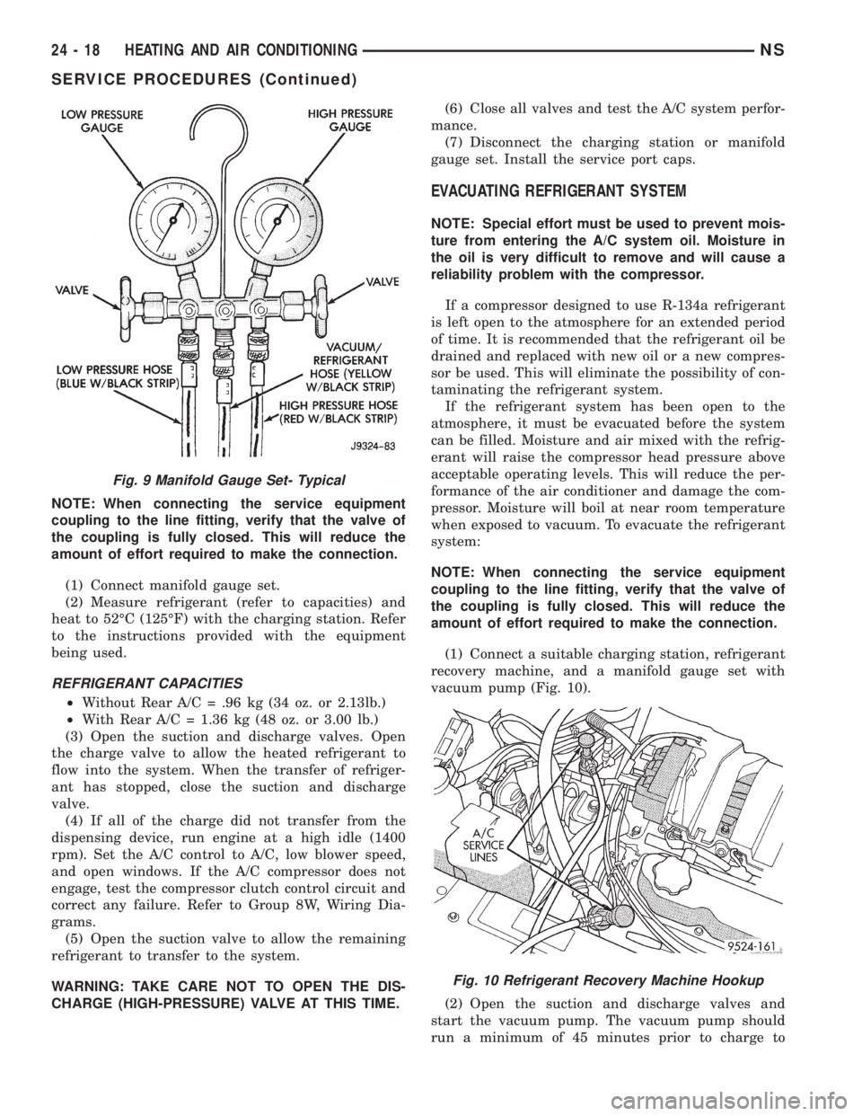
NOTE: When connecting the service equipment
coupling to the line fitting, verify that the valve of
the coupling is fully closed. This will reduce the
amount of effort required to make the connection.
(1) Connect manifold gauge set.
(2) Measure refrigerant (refer to capacities) and
heat to 52ÉC (125ÉF) with the charging station. Refer
to the instructions provided with the equipment
being used.
REFRIGERANT CAPACITIES
²Without Rear A/C = .96 kg (34 oz. or 2.13lb.)
²With Rear A/C = 1.36 kg (48 oz. or 3.00 lb.)
(3) Open the suction and discharge valves. Open
the charge valve to allow the heated refrigerant to
flow into the system. When the transfer of refriger-
ant has stopped, close the suction and discharge
valve.
(4) If all of the charge did not transfer from the
dispensing device, run engine at a high idle (1400
rpm). Set the A/C control to A/C, low blower speed,
and open windows. If the A/C compressor does not
engage, test the compressor clutch control circuit and
correct any failure. Refer to Group 8W, Wiring Dia-
grams.
(5) Open the suction valve to allow the remaining
refrigerant to transfer to the system.
WARNING: TAKE CARE NOT TO OPEN THE DIS-
CHARGE (HIGH-PRESSURE) VALVE AT THIS TIME.(6) Close all valves and test the A/C system perfor-
mance.
(7) Disconnect the charging station or manifold
gauge set. Install the service port caps.
EVACUATING REFRIGERANT SYSTEM
NOTE: Special effort must be used to prevent mois-
ture from entering the A/C system oil. Moisture in
the oil is very difficult to remove and will cause a
reliability problem with the compressor.
If a compressor designed to use R-134a refrigerant
is left open to the atmosphere for an extended period
of time. It is recommended that the refrigerant oil be
drained and replaced with new oil or a new compres-
sor be used. This will eliminate the possibility of con-
taminating the refrigerant system.
If the refrigerant system has been open to the
atmosphere, it must be evacuated before the system
can be filled. Moisture and air mixed with the refrig-
erant will raise the compressor head pressure above
acceptable operating levels. This will reduce the per-
formance of the air conditioner and damage the com-
pressor. Moisture will boil at near room temperature
when exposed to vacuum. To evacuate the refrigerant
system:
NOTE: When connecting the service equipment
coupling to the line fitting, verify that the valve of
the coupling is fully closed. This will reduce the
amount of effort required to make the connection.
(1) Connect a suitable charging station, refrigerant
recovery machine, and a manifold gauge set with
vacuum pump (Fig. 10).
(2) Open the suction and discharge valves and
start the vacuum pump. The vacuum pump should
run a minimum of 45 minutes prior to charge to
Fig. 9 Manifold Gauge Set- Typical
Fig. 10 Refrigerant Recovery Machine Hookup
24 - 18 HEATING AND AIR CONDITIONINGNS
SERVICE PROCEDURES (Continued)
Page 1837 of 1938
(2) Perform the HVAC Control Calibration Diag-
nostic and Cooldown test. Repeating the test is nec-
essary to clear the fault codes.
BLOWER MOTOR AND WHEEL ASSEMBLY
REMOVAL
(1) Remove glove box. Refer to Group 8E, Instru-
ment Panel and Systems.
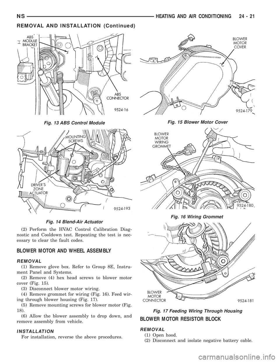
(2) Remove (4) hex head screws to blower motor
cover (Fig. 15).
(3) Disconnect blower motor wiring.
(4) Remove grommet for wiring (Fig. 16). Feed wir-
ing through blower housing (Fig. 17).
(5) Remove mounting screws for blower motor (Fig.
18).
(6) Allow the blower assembly to drop down, and
remove assembly from vehicle.
INSTALLATION
For installation, reverse the above procedures.
BLOWER MOTOR RESISTOR BLOCK
REMOVAL
(1) Open hood.
(2) Disconnect and isolate negative battery cable.
Fig. 13 ABS Control Module
Fig. 14 Blend-Air Actuator
Fig. 15 Blower Motor Cover
Fig. 16 Wiring Grommet
Fig. 17 Feeding Wiring Through Housing
NSHEATING AND AIR CONDITIONING 24 - 21
REMOVAL AND INSTALLATION (Continued)