1996 CHRYSLER VOYAGER wiring
[x] Cancel search: wiringPage 1475 of 1938
TRANSAXLE AND POWER TRANSFER UNIT
CONTENTS
page page
31TH AUTOMATIC TRANSAXLE.............. 1
41TE AUTOMATIC TRANSAXLE............. 71POWER TRANSFER UNIT................. 165
31TH AUTOMATIC TRANSAXLE
INDEX
page page
GENERAL INFORMATION
31TH TRANSAXLE........................ 2
FLUID LEVEL AND CONDITION.............. 2
SELECTION OF LUBRICANT................ 3
SPECIAL ADDITIVES...................... 3
DESCRIPTION AND OPERATION
CLUTCHES, BAND SERVOS, AND
ACCUMULATOR
...................... 3
FLOW CONTROL VALVES.................. 3
GEARSHIFT AND PARKING LOCK CONTROLS . . 4
GOVERNOR............................. 4
HYDRAULIC CONTROL SYSTEM............. 3
PRESSURE REGULATING VALVES........... 3
PRESSURE SUPPLY SYSTEM............... 3
TORQUE CONVERTER CLUTCH SOLENOID
WIRING CONNECTOR................... 4
TORQUE CONVERTER CLUTCH............. 3
DIAGNOSIS AND TESTING
CLUTCH AND SERVO AIR PRESSURE TESTS . 15
FLUID LEAKAGE-TRANSAXLE TORQUE
CONVERTER HOUSING AREA............ 15
HYDRAULIC PRESSURE TESTS............ 13
ROAD TEST............................. 4
THREE SPEED TRANSAXLE DIAGNOSIS AND
TESTS............................... 4
SERVICE PROCEDURES
ALUMINUM THREAD REPAIR.............. 18
FLUID AND FILTER CHANGE............... 16
FLUID DRAIN AND REFILL................. 18
FLUSHING COOLERS AND TUBES.......... 18
OIL PUMP VOLUME CHECK............... 19
REMOVAL AND INSTALLATION
FRONT PUMP OIL SEAL.................. 21
PARK/NEUTRAL STARTING AND BACK-UP
LAMP SWITCH........................ 19
TRANSAXLE AND TORQUE CONVERTER
REMOVAL............................ 20
VEHICLE SPEED SENSOR PINION GEAR..... 19DISASSEMBLY AND ASSEMBLY
ACCUMULATOR-RECONDITION............ 36
DIFFERENTIAL REPAIR................... 46
FRONT CLUTCH-RECONDITION............ 32
FRONT PLANETARY & ANNULUS GEAR-
RECONDITION........................ 35
KICKDOWN SERVO (CONTROLLED LOAD)-
RECONDITION........................ 37
LOW/REVERSE (REAR)
SERVO-RECONDITION.................. 36
OIL PUMP-RECONDITION................. 31
OUTPUT SHAFT REPAIR.................. 43
PARKING PAWL......................... 42
REAR CLUTCH-RECONDITION............. 33
TRANSAXLE........................... 21
TRANSFER SHAFT REPAIR................ 38
VALVE BODY RECONDITION............... 27
CLEANING AND INSPECTION
VALVE BODY........................... 50
ADJUSTMENTS
BAND ADJUSTMENT..................... 51
BEARING ADJUSTMENT PROCEDURES...... 52
DIFFERENTIAL BEARING................. 53
GEARSHIFT CABLE ADJUSTMENT.......... 51
HYDRAULIC CONTROL PRESSURE
ADJUSTMENTS....................... 52
OUTPUT SHAFT BEARING................ 52
THROTTLE PRESSURE LINKAGE
ADJUSTMENT......................... 51
TRANSFER SHAFT BEARING.............. 54
SCHEMATICS AND DIAGRAMS
31TH TRANSAXLE HYDRAULIC SCHEMATIC . . 56
SPECIFICATIONS
31TH AUTOMATIC TRANSAXLE............. 64
31TH TORQUE SPECIFICATIONS........... 65
SPECIAL TOOLS
31TH AUTOMATIC TRANSAXLE............. 66
NSTRANSAXLE AND POWER TRANSFER UNIT 21 - 1
Page 1478 of 1938
GEARSHIFT AND PARKING LOCK CONTROLS
The transaxle is controlled by a lever type gear-
shift incorporated within the steering column. The
control has six selector lever positions: P (park), R
(reverse), N (neutral), and D (drive), 2 (second), and
1 (first). The parking lock is applied by moving the
selector lever past a gate to the P position.Do not
apply the parking lock until the vehicle has
stopped; otherwise, a severe ratchet noise will
occur.
TORQUE CONVERTER CLUTCH SOLENOID WIRING
CONNECTOR
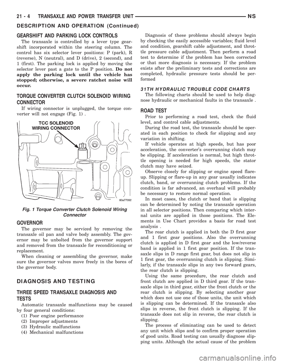
If wiring connector is unplugged, the torque con-
verter will not engage (Fig. 1) .
GOVERNOR
The governor may be serviced by removing the
transaxle oil pan and valve body assembly. The gov-
ernor may be unbolted from the governor support
and removed from the transaxle for reconditioning or
replacement.
When cleaning or assembling the governor, make
sure the governor valves move freely in the bores of
the governor body.
DIAGNOSIS AND TESTING
THREE SPEED TRANSAXLE DIAGNOSIS AND
TESTS
Automatic transaxle malfunctions may be caused
by four general conditions:
(1) Poor engine performance
(2) Improper adjustments
(3) Hydraulic malfunctions
(4) Mechanical malfunctionsDiagnosis of these problems should always begin
by checking the easily accessible variables; fluid level
and condition, gearshift cable adjustment, and throt-
tle pressure cable adjustment. Then perform a road
test to determine if the problem has been corrected
or that more diagnosis is necessary. If the problem
exists after the preliminary tests and corrections are
completed, hydraulic pressure tests should be per-
formed
31TH HYDRAULIC TROUBLE CODE CHARTS
The following charts should be used to help diag-
nose hydraulic or mechanical faults in the transaxle .
ROAD TEST
Prior to performing a road test, check the fluid
level, and control cable adjustments.
During the road test, the transaxle should be oper-
ated in each position to check for slipping and any
variation in shifting.
If vehicle operates at high speeds, but has poor
acceleration, the converter's overrunning clutch may
be slipping. If acceleration is normal, but high throt-
tle opening is needed for high speeds, the stator
clutch may have seized.
Observe closely for slipping or engine speed flare-
up. Slipping or flare-up in any gear usually indicates
clutch, band, or overrunning clutch problems. If the
condition is far advanced, an overhaul will probably
be necessary to restore normal operation.
In most cases, the clutch or band that is slipping
can be determined by noting the transaxle operation
in all selector positions. Then comparing which inter-
nal units are applied in those positions. The Ele-
ments in Use Chart provides a basis for road test
analysis .
The rear clutch is applied in both the D first gear
and 1 first gear positions. Also the overrunning
clutch is applied in D first gear and the low/reverse
band is applied in 1 first gear position. If the tran-
saxle slips in D range first gear, but does not slip in
1 first gear, the overrunning clutch is slipping. Simi-
larly, if the transaxle slips in any two forward gears,
the rear clutch is slipping.
Using the same procedure, the rear clutch and
front clutch are applied in D third gear. If the tran-
saxle slips in third gear, either the front clutch or the
rear clutch is slipping. By selecting another gear
which does not use one of those units, the unit which
is slipping can be determined. If the transaxle also
slips in reverse, the front clutch is slipping. If the
transaxle does not slip in reverse, the rear clutch is
slipping.
The process of eliminating can be used to detect
any unit which slips and to confirm proper operation
of good units. Road testing can usually diagnose slip-
ping units. Although the actual cause of the problem
Fig. 1 Torque Converter Clutch Solenoid Wiring
Connector
21 - 4 TRANSAXLE AND POWER TRANSFER UNITNS
DESCRIPTION AND OPERATION (Continued)
Page 1493 of 1938
(5) Connect the BLUE pressure line to the OUT-
LET (From) cooler line.
(6) Connect the CLEAR return line to the INLET
(To) cooler line
(7) Turn pump ON for two to three minutes to
flush cooler(s) and lines. Monitor pressure readings
and clear return lines. Pressure readings should sta-
bilize below 20 psi. for vehicles equipped with a sin-
gle cooler and 30 psi. for vehicles equipped with dual
coolers. If flow is intermittent or exceeds these pres-
sures, replace cooler.
(8) Turn pump OFF.
(9) Disconnect CLEAR suction line from reservoir
at cover plate. Disconnect CLEAR return line at
cover plate, and place it in a drain pan.
(10) Turn pump ON for 30 seconds to purge flush-
ing solution from cooler and lines. Turn pump OFF.
(11) Place CLEAR suction line into a one quart
container of Mopar ATF Plus 3ttype 7176 automatic
transmission fluid.
(12) Turn pump ON until all transmission fluid is
removed from the one quart container and lines. This
purges any residual cleaning solvent from the trans-
mission cooler and lines. Turn pump OFF.
(13) Disconnect alligator clips from battery. Recon-
nect flusher lines to cover plate, and remove flushing
adapters from cooler lines.
OIL PUMP VOLUME CHECK
After the new or repaired transmission has been
installed, fill to the proper level with MopartAT F
PLUS 3 (Type 7176) automatic transmission fluid.
The volume should be checked using the following
procedure:
(1) Disconnect theFrom coolerline at the trans-
mission and place a collecting container under the
disconnected line.
CAUTION: With the fluid set at the proper level,
fluid collection should not exceed (1) quart or inter-
nal damage to the transmission may occur.
(2) Run the engineat curb idle speed, with the
shift selector in neutral.
(3) If fluid flow is intermittent or it takes more
than 20 seconds to collect one quart of ATF PLUS 3,
disconnect theTo Coolerline at the transaxle.
(4) Refill the transaxle to proper level and recheck
pump volume.
(5) If flow is found to be within acceptable limits,
replace the cooler. Then fill transmission to the
proper level, using MopartATF PLUS 3 (Type 7176)
automatic transmission fluid.
(6) If fluid flow is still found to be inadequate,
check the line pressure using the Transaxle Hydrau-
lic Pressure Test procedure.
REMOVAL AND INSTALLATION
VEHICLE SPEED SENSOR PINION GEAR
When the sensor is removed for any reason, a
NEW O-ring must be installed on its outside diame-
ter.
REMOVAL
(1) Remove harness connector from sensor. Make
sure weatherseal stays on harness connector.
(2) Remove bolt securing the sensor in the exten-
sion housing.
(3) Carefully pull sensor and pinion gear assembly
out of extension housing.
(4) Remove pinion gear from sensor.
INSTALLATION
(1) To install, reverse the above procedure. Make
sure extension housing and sensor flange are clean
prior to installation. Always use a NEW sensor
O-ring.
(2) Tighten bolt to 7 N´m (60 in. lbs.). Tighten
speedometer cable to 4 N´m (35 in. lbs.).
PARK/NEUTRAL STARTING AND BACK-UP LAMP
SWITCH
TEST
The park/neutral starting switch is the center ter-
minal of the 3 terminal switch. It provides ground for
the starter solenoid circuit through the selector lever
in only Park and Neutral positions.
(1) To test switch, remove wiring connector from
switch and test for continuity between center pin of
switch and transaxle case. Continuity should exist
only when transaxle is in Park or Neutral.
(2) Check gearshift cable adjustment before replac-
ing a switch which tests bad.
REMOVAL
(1) Unscrew switch from transaxle case allowing
fluid to drain into a container. Move selector lever to
Park, then to Neutral position, and inspect to see the
switch operating lever fingers are centered in switch
opening.
INSTALLATION
(1) Screw the switch with a new seal into tran-
saxle case and tighten to 33 N´m (24 ft. lbs.). Retest
switch with the test lamp.
(2) Add fluid to transaxle to bring up to proper
level.
(3) The back-up lamp switch circuit is through the
two outside terminals of the 3 terminal switch.
(4) To test switch, remove wiring connector from
switch and test for continuity between the two out-
side pins.
NSTRANSAXLE AND POWER TRANSFER UNIT 21 - 19
SERVICE PROCEDURES (Continued)
Page 1553 of 1938
If a problem arises with the shifter position indica-
tor, consult the following chart for diagnostic infor-
mation. If the malfunction cannot be corrected using
the chart, consult the proper diagnostic manual.
To replace the shifter position indicator, refer to
Group 8E, Instrument Panel And Gauges.SERVICE PROCEDURES
FLUID AND FILTER CHANGE
When the factory fill fluid is changed, only fluids
labeled MOPARtATF PLUS 3 (Automatic Transmis-
sion fluid) Type 7176 should be used.
If the transaxle is disassembled for any reason, the
fluid and filter should be changed.
30,000 MILE TRANSAXLE OIL CHANGE
When a vehicle attains 30,000 miles on its odome-
ter it is recommended that the transaxle oil be
changed. To change the oil, use the procedure that
follows:
It is recommended that a transaxle fluid exchanger
(ATF 2000+ or equivalent) be used to replace the
used fluid in the transaxle. If a fluid exchanger is not
available use a fluid suction pump (Vaculayor equiv-
alent) to draw the fluid out of the dipstick tube. If a
fluid suction pump is not available remove the oil
pan and drain the fluid.
CAUTION: Chrysler Corporation does not recom-
mend using any fluid exchanger that introduces
additives into the transaxle.
TRANSAXLE FLUID EXCHANGER METHOD
(1) To perform the transaxle fluid exchange, the
transaxle must be at operating temperature. Drive
the vehicle till it reaches full operating temperature.
(2) Verify that the fill tank on the transaxle fluid
exchanger (ATF 2000+ or equivalent) is clean and
dry.
(3) Fill the tank to the recommended fill capacity
with Mopar ATF Plus 3 Type 7176.
(4) Hookup the vehicle to the machine following
the manufacturers instructions. Perform the
exchange procedure following the instructions pro-
vided with the machine.
(5) Once machine has completed the fluid
exchange. Check the fluid level and condition and fill
to proper level with Mopar ATF Plus 3 Type 7176.
NOTE: Verify that the transaxle cooler lines are
tightened to proper specifications. Cooler line
torque specification is 2 N´m (18 in. lbs.).
CONDITION POSSIBLE CAUSE
ALL PRND3L DISPLAY
LIGHTS9ON9IN P&N
GEAR POSITIONS1.Check wiring and
connectors
2. Faulty trans. range
sensor
3. Faulty manual lever
ALL DISPLAY LIGHTS
9ON9IN ALL GEAR
POSITIONS1. Check wiring &
connectors
2. Faulty trans. range
sensor
3. Faulty manual lever
4. CCD communication
malfunction
5. Check oil level
ALL DISPLAY LIGHTS
9OFF91. Normal transient
condition between P&R
and R&N gear positions
2. Check shift lever
linkage
3. Body controller
malfunction
4. Check wiring and
connectors
5. Faulty cluster
ALL DISPLAY LIGHTS
9OFF9ACCOMPANIED
BY A9NO BUS9
MESSAGE1. CCD communication
malfunction
DISPLAY LIGHTS OUT
OF SEQUENCE WITH
SHIFT LEVER1. Check wiring and
connectors
2. Faulty trans. range
sensor
3. Faulty manual lever
4. CCD communication
malfunction
NSTRANSAXLE AND POWER TRANSFER UNIT 21 - 79
DIAGNOSIS AND TESTING (Continued)
Page 1563 of 1938
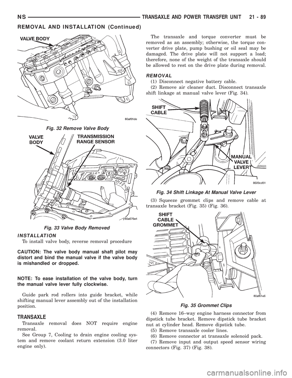
INSTALLATION
To install valve body, reverse removal procedure
CAUTION: The valve body manual shaft pilot may
distort and bind the manual valve if the valve body
is mishandled or dropped.
NOTE: To ease installation of the valve body, turn
the manual valve lever fully clockwise.
Guide park rod rollers into guide bracket, while
shifting manual lever assembly out of the installation
position.
TRANSAXLE
Transaxle removal does NOT require engine
removal.
See Group 7, Cooling to drain engine cooling sys-
tem and remove coolant return extension (3.0 liter
engine only).The transaxle and torque converter must be
removed as an assembly; otherwise, the torque con-
verter drive plate, pump bushing or oil seal may be
damaged. The drive plate will not support a load;
therefore, none of the weight of the transaxle should
be allowed to rest on the drive plate during removal.
REMOVAL
(1) Disconnect negative battery cable.
(2) Remove air cleaner duct. Disconnect transaxle
shift linkage at manual valve lever (Fig. 34).
(3) Squeeze grommet clips and remove cable at
transaxle bracket (Fig. 35) (Fig. 36).
(4) Remove 16±way engine harness connector from
dipstick tube bracket. Remove dipstick tube bracket
nut at cylinder head. Remove dipstick tube.
(5) Remove transaxle cooler lines.
(6) Remove connector at transaxle solenoid pack.
(7) Remove input and output speed sensor wiring
connectors (Fig. 37) (Fig. 38).
Fig. 32 Remove Valve Body
Fig. 33 Valve Body Removed
Fig. 34 Shift Linkage At Manual Valve Lever
Fig. 35 Grommet Clips
NSTRANSAXLE AND POWER TRANSFER UNIT 21 - 89
REMOVAL AND INSTALLATION (Continued)
Page 1564 of 1938
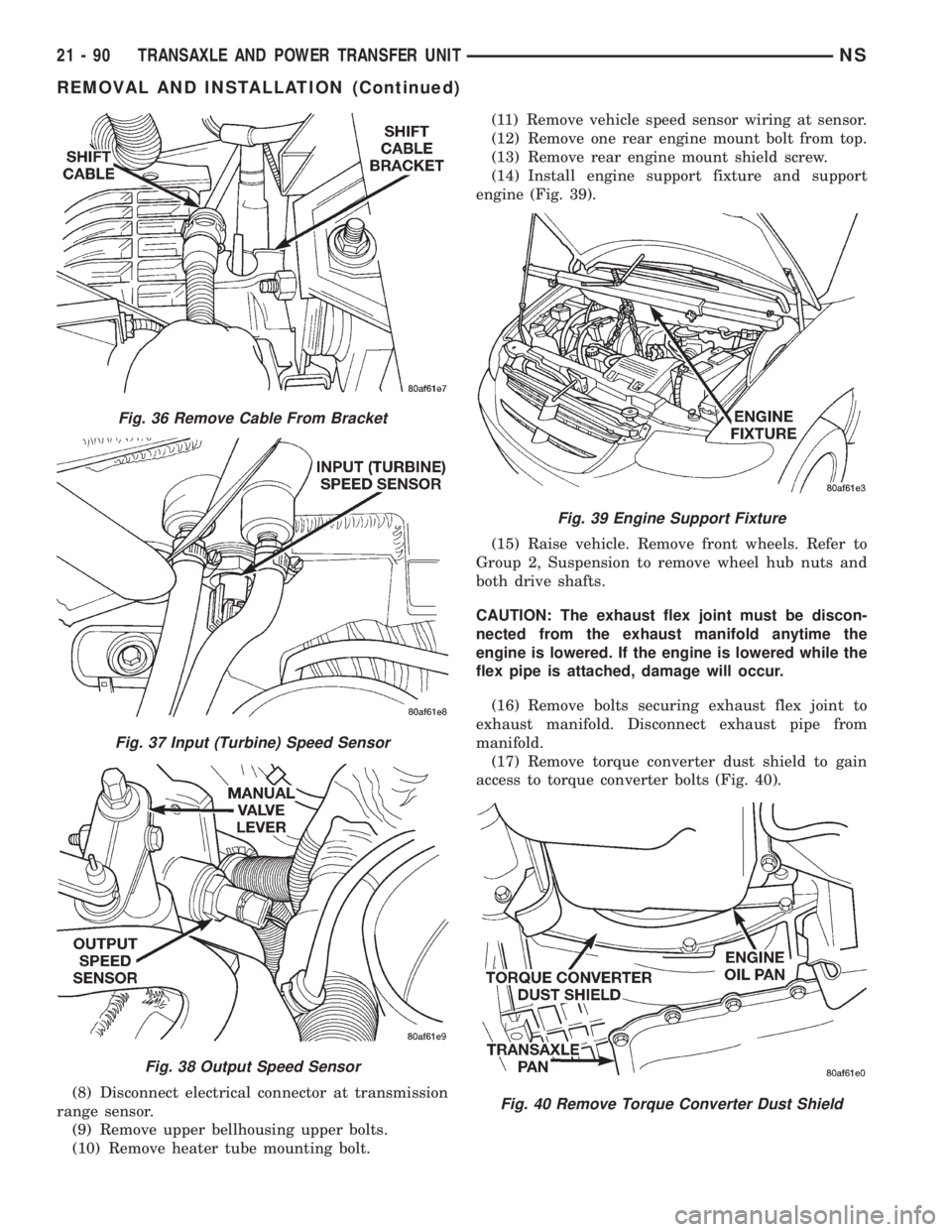
(8) Disconnect electrical connector at transmission
range sensor.
(9) Remove upper bellhousing upper bolts.
(10) Remove heater tube mounting bolt.(11) Remove vehicle speed sensor wiring at sensor.
(12) Remove one rear engine mount bolt from top.
(13) Remove rear engine mount shield screw.
(14) Install engine support fixture and support
engine (Fig. 39).
(15) Raise vehicle. Remove front wheels. Refer to
Group 2, Suspension to remove wheel hub nuts and
both drive shafts.
CAUTION: The exhaust flex joint must be discon-
nected from the exhaust manifold anytime the
engine is lowered. If the engine is lowered while the
flex pipe is attached, damage will occur.
(16) Remove bolts securing exhaust flex joint to
exhaust manifold. Disconnect exhaust pipe from
manifold.
(17) Remove torque converter dust shield to gain
access to torque converter bolts (Fig. 40).
Fig. 36 Remove Cable From Bracket
Fig. 37 Input (Turbine) Speed Sensor
Fig. 38 Output Speed Sensor
Fig. 39 Engine Support Fixture
Fig. 40 Remove Torque Converter Dust Shield
21 - 90 TRANSAXLE AND POWER TRANSFER UNITNS
REMOVAL AND INSTALLATION (Continued)
Page 1665 of 1938
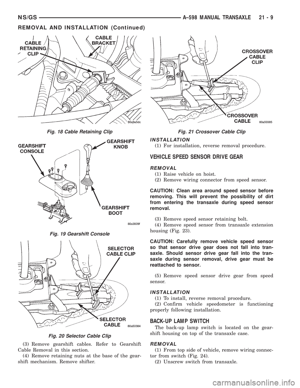
(3) Remove gearshift cables. Refer to Gearshift
Cable Removal in this section.
(4) Remove retaining nuts at the base of the gear-
shift mechanism. Remove shifter.
INSTALLATION
(1) For installation, reverse removal procedure.
VEHICLE SPEED SENSOR DRIVE GEAR
REMOVAL
(1) Raise vehicle on hoist.
(2) Remove wiring connector from speed sensor.
CAUTION: Clean area around speed sensor before
removing. This will prevent the possibility of dirt
from entering the transaxle during speed sensor
removal.
(3) Remove speed sensor retaining bolt.
(4) Remove speed sensor from transaxle extension
housing (Fig. 23).
CAUTION: Carefully remove vehicle speed sensor
so that sensor drive gear does not fall into tran-
saxle. Should sensor drive gear fall into the tran-
saxle during sensor removal, drive gear must be
reattached to sensor.
(5) Remove speed sensor drive gear from speed
sensor.
INSTALLATION
(1) To install, reverse removal procedure.
(2) Confirm vehicle speedometer is functioning
properly following installation.
BACK-UP LAMP SWITCH
The back-up lamp switch is located on the gear-
shift housing on top of the transaxle case.
REMOVAL
(1) From top side of vehicle, remove wiring connec-
tor from switch (Fig. 24).
(2) Unscrew switch from transaxle.
Fig. 18 Cable Retaining Clip
Fig. 19 Gearshift Console
Fig. 20 Selector Cable Clip
Fig. 21 Crossover Cable Clip
NS/GSA±598 MANUAL TRANSAXLE 21 - 9
REMOVAL AND INSTALLATION (Continued)
Page 1668 of 1938
DIFFERENTIAL BEARING RETAINER AXLE
SEAL
REMOVAL
(1) Remove axle shaft. Refer to Group 2, Suspen-
sion and Driveshafts for service procedures.
(2) Insert a flat±blade pry tool into the axle seal
bore.
(3) Using the pry tool, carefully pop out the seal
taking care not to nick the seal bore.
INSTALLATION
(1) Clean axle shaft seal bore of any excess seal-
ant.
(2) Align axle shaft seal with axle shaft seal bore.
(3) Position axle seal at extension housing.
(4) Using Tool L-4520 and Tool C-4171, tap seal
into position.
SHIFT SHAFT SEALS
It isnotnecessary to remove the shift shaft cover
from the transaxle to service the shift shaft seals.
REMOVAL
(1) Remove the shift lever from the seal that is to
be serviced. Refer to shift lever removal for service
procedure.
(2) Using a pick tool, pry up on the shift shaft seal
and remove seal from bore.
INSTALLATION
(1) Position new shift shaft seal in bore.
(2) Install shift shaft seal into bore using an
appropriate size deep±well socket.
TRANSAXLE
The following items can be serviced without remov-
ing the transaxle from the vehicle:
²Gearshift housing
²5th speed synchronizer
²5th speed gear
²Roller detents and springs
²Speedometer pinion
²Vehicle speed sensor
²Bearing retainer plate.
²All external covers
²Shift shaft seals
²Axle shaft seals
To service any other component of the A-598 tran-
saxle you must remove it from the vehicle.
REMOVAL
(1) Disconnect battery negative cable.
(2) Remove air intake hose. Disconnect air mass
meter connector.
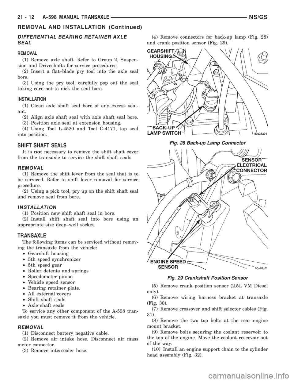
(3) Remove intercooler hose.(4) Remove connectors for back-up lamp (Fig. 28)
and crank position sensor (Fig. 29).
(5) Remove crank position sensor (2.5L VM Diesel
only).
(6) Remove wiring harness bracket at transaxle
(Fig. 30).
(7) Remove crossover and shift selector cables (Fig.
31).
(8) Remove the two top bolts at the rear engine
mount bracket.
(9) Remove bolts securing the coolant reservoir to
the top of the engine. Move the coolant reservoir out
of the way.
(10) Install an engine support chain to the cylinder
head assembly (Fig. 32).
Fig. 28 Back-up Lamp Connector
Fig. 29 Crankshaft Position Sensor
21 - 12 A±598 MANUAL TRANSAXLENS/GS
REMOVAL AND INSTALLATION (Continued)