1996 CHRYSLER VOYAGER wiring
[x] Cancel search: wiringPage 1669 of 1938
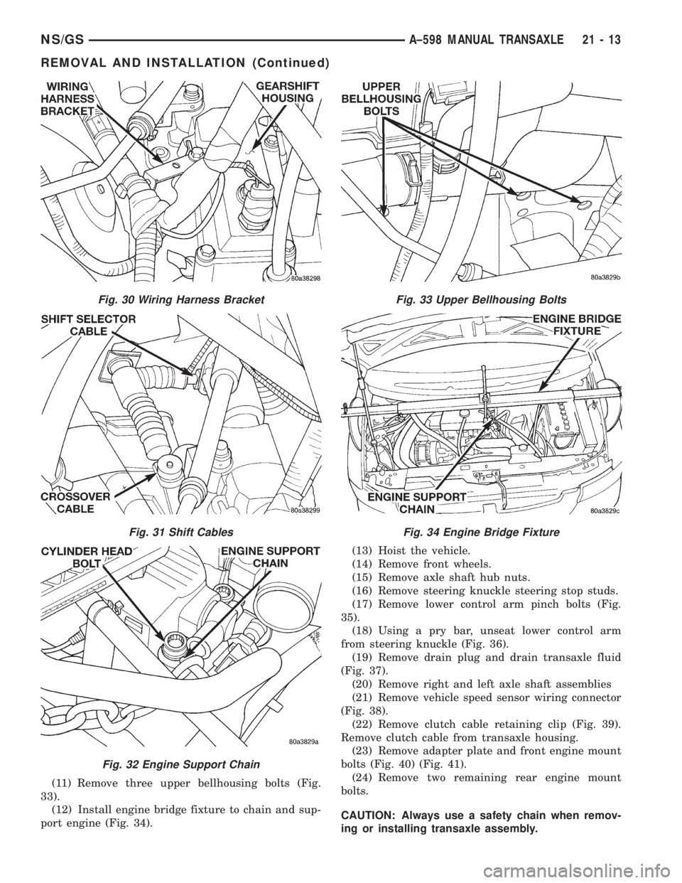
(11) Remove three upper bellhousing bolts (Fig.
33).
(12) Install engine bridge fixture to chain and sup-
port engine (Fig. 34).(13) Hoist the vehicle.
(14) Remove front wheels.
(15) Remove axle shaft hub nuts.
(16) Remove steering knuckle steering stop studs.
(17) Remove lower control arm pinch bolts (Fig.
35).
(18) Using a pry bar, unseat lower control arm
from steering knuckle (Fig. 36).
(19) Remove drain plug and drain transaxle fluid
(Fig. 37).
(20) Remove right and left axle shaft assemblies
(21) Remove vehicle speed sensor wiring connector
(Fig. 38).
(22) Remove clutch cable retaining clip (Fig. 39).
Remove clutch cable from transaxle housing.
(23) Remove adapter plate and front engine mount
bolts (Fig. 40) (Fig. 41).
(24) Remove two remaining rear engine mount
bolts.
CAUTION: Always use a safety chain when remov-
ing or installing transaxle assembly.
Fig. 30 Wiring Harness Bracket
Fig. 31 Shift Cables
Fig. 32 Engine Support Chain
Fig. 33 Upper Bellhousing Bolts
Fig. 34 Engine Bridge Fixture
NS/GSA±598 MANUAL TRANSAXLE 21 - 13
REMOVAL AND INSTALLATION (Continued)
Page 1672 of 1938
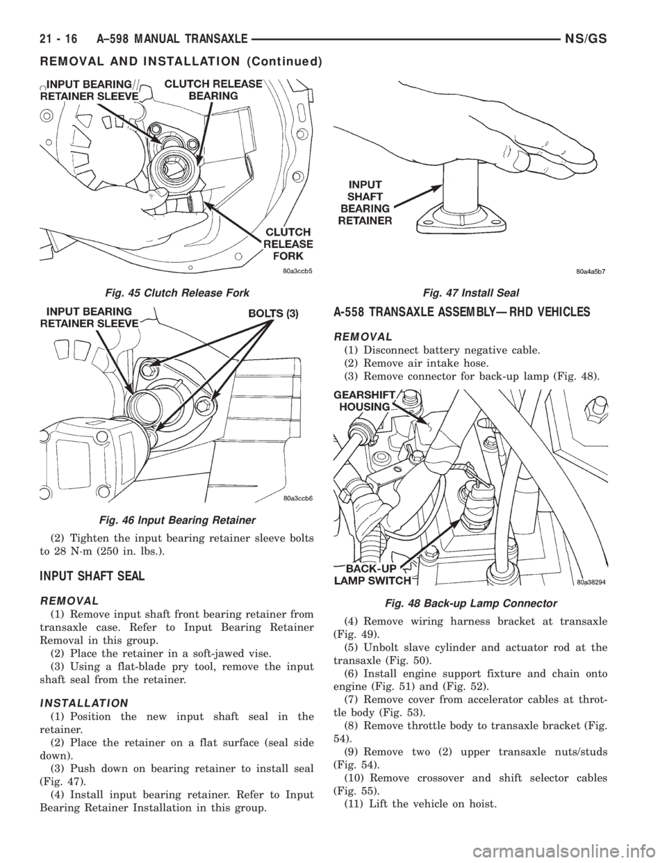
(2) Tighten the input bearing retainer sleeve bolts
to 28 N´m (250 in. lbs.).
INPUT SHAFT SEAL
REMOVAL
(1) Remove input shaft front bearing retainer from
transaxle case. Refer to Input Bearing Retainer
Removal in this group.
(2) Place the retainer in a soft-jawed vise.
(3) Using a flat-blade pry tool, remove the input
shaft seal from the retainer.
INSTALLATION
(1) Position the new input shaft seal in the
retainer.
(2) Place the retainer on a flat surface (seal side
down).
(3) Push down on bearing retainer to install seal
(Fig. 47).
(4) Install input bearing retainer. Refer to Input
Bearing Retainer Installation in this group.
A-558 TRANSAXLE ASSEMBLYÐRHD VEHICLES
REMOVAL
(1) Disconnect battery negative cable.
(2) Remove air intake hose.
(3) Remove connector for back-up lamp (Fig. 48).
(4) Remove wiring harness bracket at transaxle
(Fig. 49).
(5) Unbolt slave cylinder and actuator rod at the
transaxle (Fig. 50).
(6) Install engine support fixture and chain onto
engine (Fig. 51) and (Fig. 52).
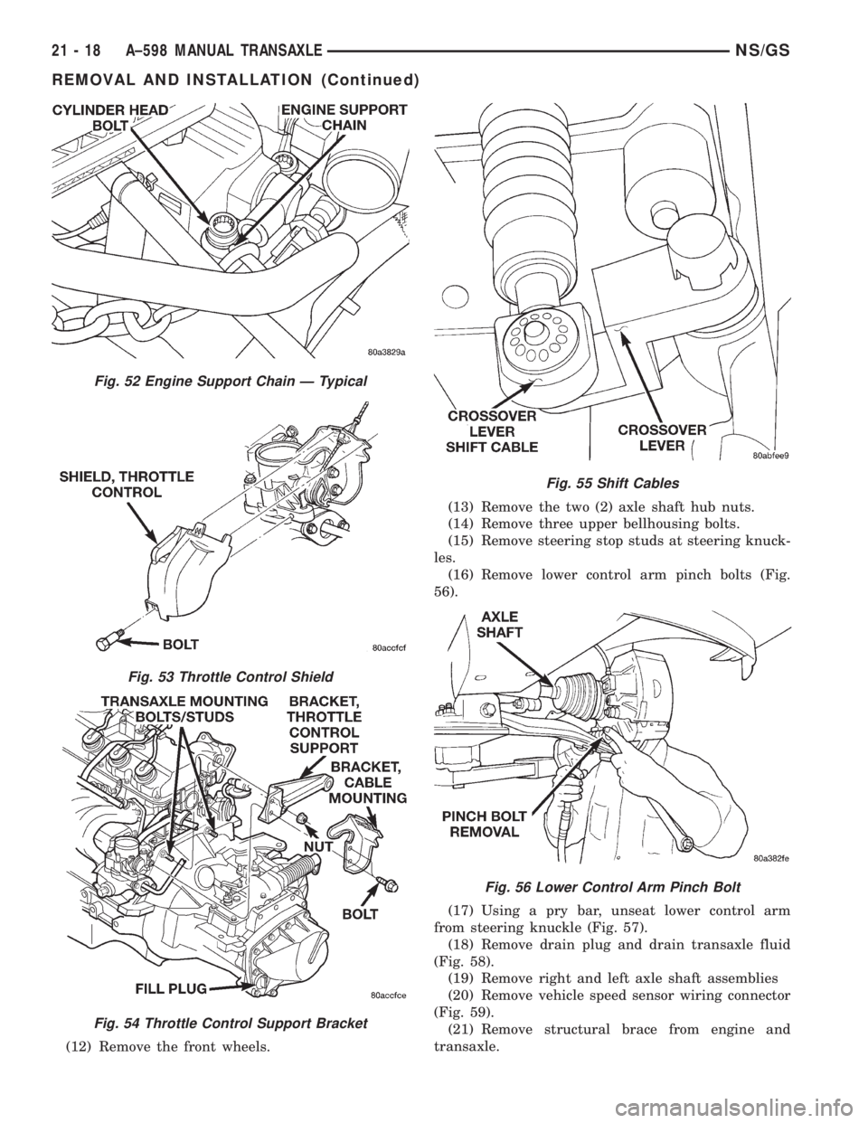
(7) Remove cover from accelerator cables at throt-
tle body (Fig. 53).
(8) Remove throttle body to transaxle bracket (Fig.
54).
(9) Remove two (2) upper transaxle nuts/studs
(Fig. 54).
(10) Remove crossover and shift selector cables
(Fig. 55).
(11) Lift the vehicle on hoist.
Fig. 45 Clutch Release Fork
Fig. 46 Input Bearing Retainer
Fig. 47 Install Seal
Fig. 48 Back-up Lamp Connector
21 - 16 A±598 MANUAL TRANSAXLENS/GS
REMOVAL AND INSTALLATION (Continued)
Page 1673 of 1938
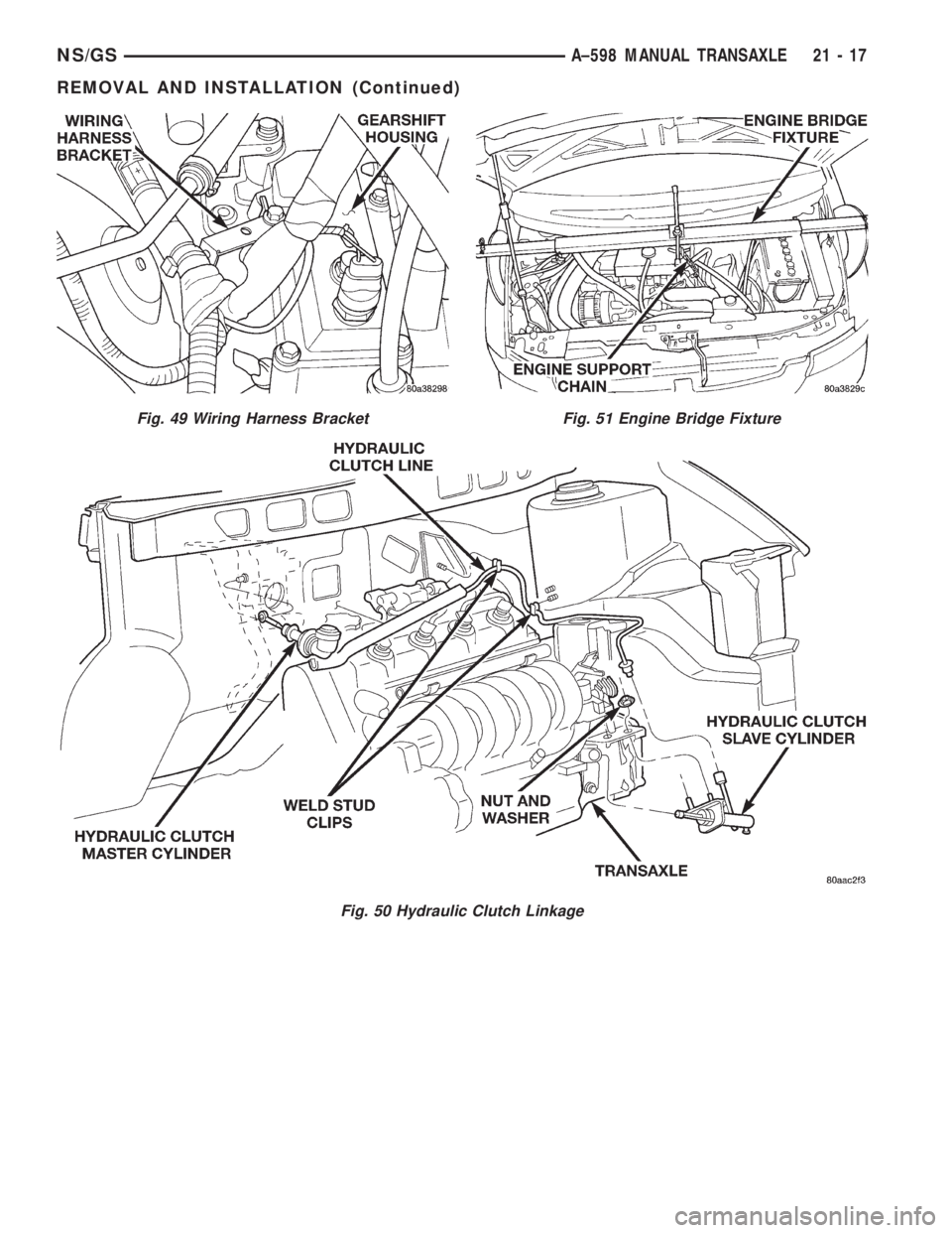
Fig. 49 Wiring Harness Bracket
Fig. 50 Hydraulic Clutch Linkage
Fig. 51 Engine Bridge Fixture
NS/GSA±598 MANUAL TRANSAXLE 21 - 17
REMOVAL AND INSTALLATION (Continued)
Page 1674 of 1938
(12) Remove the front wheels.(13) Remove the two (2) axle shaft hub nuts.
(14) Remove three upper bellhousing bolts.
(15) Remove steering stop studs at steering knuck-
les.
(16) Remove lower control arm pinch bolts (Fig.
56).
(17) Using a pry bar, unseat lower control arm
from steering knuckle (Fig. 57).
(18) Remove drain plug and drain transaxle fluid
(Fig. 58).
(19) Remove right and left axle shaft assemblies
(20) Remove vehicle speed sensor wiring connector
(Fig. 59).
(21) Remove structural brace from engine and
transaxle.
Fig. 52 Engine Support Chain Ð Typical
Fig. 53 Throttle Control Shield
Fig. 54 Throttle Control Support Bracket
Fig. 55 Shift Cables
Fig. 56 Lower Control Arm Pinch Bolt
21 - 18 A±598 MANUAL TRANSAXLENS/GS
REMOVAL AND INSTALLATION (Continued)
Page 1675 of 1938
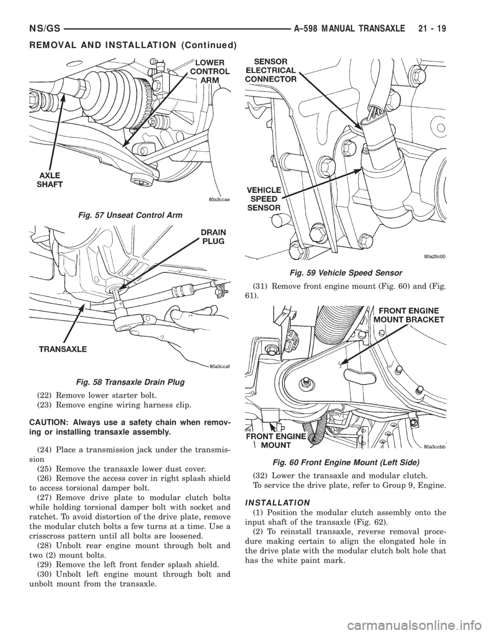
(22) Remove lower starter bolt.
(23) Remove engine wiring harness clip.
CAUTION: Always use a safety chain when remov-
ing or installing transaxle assembly.
(24) Place a transmission jack under the transmis-
sion
(25) Remove the transaxle lower dust cover.
(26) Remove the access cover in right splash shield
to access torsional damper bolt.
(27) Remove drive plate to modular clutch bolts
while holding torsional damper bolt with socket and
ratchet. To avoid distortion of the drive plate, remove
the modular clutch bolts a few turns at a time. Use a
crisscross pattern until all bolts are loosened.
(28) Unbolt rear engine mount through bolt and
two (2) mount bolts.
(29) Remove the left front fender splash shield.
(30) Unbolt left engine mount through bolt and
unbolt mount from the transaxle.(31) Remove front engine mount (Fig. 60) and (Fig.
61).
(32) Lower the transaxle and modular clutch.
To service the drive plate, refer to Group 9, Engine.
INSTALLATION
(1) Position the modular clutch assembly onto the
input shaft of the transaxle (Fig. 62).
(2) To reinstall transaxle, reverse removal proce-
dure making certain to align the elongated hole in
the drive plate with the modular clutch bolt hole that
has the white paint mark.
Fig. 57 Unseat Control Arm
Fig. 58 Transaxle Drain Plug
Fig. 59 Vehicle Speed Sensor
Fig. 60 Front Engine Mount (Left Side)
NS/GSA±598 MANUAL TRANSAXLE 21 - 19
REMOVAL AND INSTALLATION (Continued)
Page 1731 of 1938
BODY
CONTENTS
page page
BODY COMPONENT SERVICE.............. 22
GENERAL SERVICE INFORMATION........... 1
PAINT.................................. 2SEATS .................................. 9
STATIONARY GLASS....................... 4
GENERAL SERVICE INFORMATION
INDEX
page
GENERAL INFORMATION
SAFETY PRECAUTIONS AND WARNINGS...... 1
GENERAL INFORMATION
SAFETY PRECAUTIONS AND WARNINGS
WARNING: EYE PROTECTION SHOULD BE USED
WHEN SERVICING GLASS COMPONENTS. PER-
SONAL INJURY CAN RESULT.
USE A OSHA APPROVED BREATHING FILTER
WHEN SPRAYING PAINT OR SOLVENTS IN A CON-
FINED AREA. PERSONAL INJURY CAN RESULT.
AVOID PROLONGED SKIN CONTACT WITH
PETROLEUM OR ALCOHOL± BASED CLEANING
SOLVENTS. PERSONAL INJURY CAN RESULT.
DO NOT STAND UNDER A HOISTED VEHICLE
THAT IS NOT PROPERLY SUPPORTED ON SAFETY
STANDS. PERSONAL INJURY CAN RESULT.
CAUTION: When holes must be drilled or punched
in an inner body panel, verify depth of space to the
outer body panel, electrical wiring, or other compo-
nents. Damage to vehicle can result.
Do not weld exterior panels unless combustible
material on the interior of vehicle is removed from
the repair area. Fire or hazardous conditions, can
result.
Always have a fire extinguisher ready for use
when welding.
Disconnect the negative (-) cable clamp from the
battery when servicing electrical components that
are live when the ignition is OFF. Damage to electri-
cal system can result.Do not use abrasive chemicals or compounds on
painted surfaces. Damage to finish can result.
Do not use harsh alkaline based cleaning sol-
vents on painted or upholstered surfaces. Damage
to finish or color can result.
Do not hammer or pound on plastic trim panel
when servicing interior trim. Plastic panels can
break.
Chrysler Corporation uses many different types of
push-in fasteners to secure the interior and exterior
trim to the body. Most of these fasteners can be
reused to assemble the trim during various repair
procedures. At times, a push-in fastener cannot be
removed without damaging the fastener or the com-
ponent it is holding. If it is not possible to remove a
fastener without damaging a component or body, cut
or break the fastener and use a new one when
installing the component. Never pry or pound on a
plastic or pressed-board trim component. Using a
suitable fork-type prying device, pry the fastener
from the retaining hole behind the component being
removed. When installing, verify fastener alignment
with the retaining hole by hand. Push directly on or
over the fastener until it seats. Apply a low-force pull
to the panel to verify that it is secure.
When it is necessary to remove components to ser-
vice another, it should not be necessary to apply
excessive force or bend a component to remove it.
Before damaging a trim component, verify hidden
fasteners or captured edges holding the component in
place.
NSBODY 23 - 1
Page 1757 of 1938
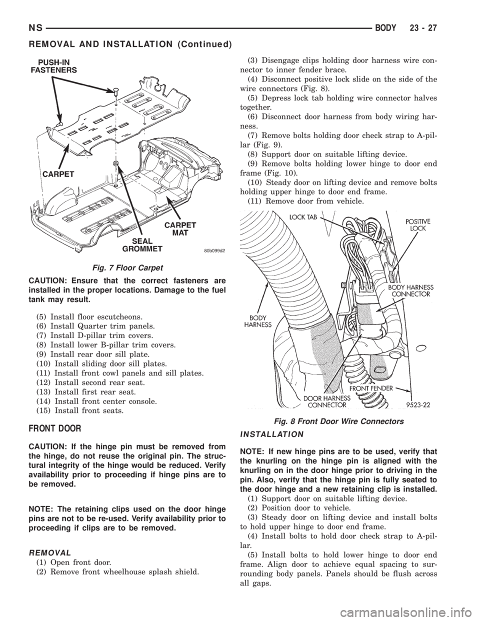
CAUTION: Ensure that the correct fasteners are
installed in the proper locations. Damage to the fuel
tank may result.
(5) Install floor escutcheons.
(6) Install Quarter trim panels.
(7) Install D-pillar trim covers.
(8) Install lower B-pillar trim covers.
(9) Install rear door sill plate.
(10) Install sliding door sill plates.
(11) Install front cowl panels and sill plates.
(12) Install second rear seat.
(13) Install first rear seat.
(14) Install front center console.
(15) Install front seats.
FRONT DOOR
CAUTION: If the hinge pin must be removed from
the hinge, do not reuse the original pin. The struc-
tural integrity of the hinge would be reduced. Verify
availability prior to proceeding if hinge pins are to
be removed.
NOTE: The retaining clips used on the door hinge
pins are not to be re-used. Verify availability prior to
proceeding if clips are to be removed.
REMOVAL
(1) Open front door.
(2) Remove front wheelhouse splash shield.(3) Disengage clips holding door harness wire con-
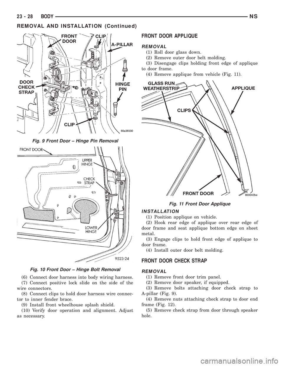
nector to inner fender brace.
(4) Disconnect positive lock slide on the side of the
wire connectors (Fig. 8).
(5) Depress lock tab holding wire connector halves
together.
(6) Disconnect door harness from body wiring har-
ness.
(7) Remove bolts holding door check strap to A-pil-
lar (Fig. 9).
(8) Support door on suitable lifting device.
(9) Remove bolts holding lower hinge to door end
frame (Fig. 10).
(10) Steady door on lifting device and remove bolts
holding upper hinge to door end frame.
(11) Remove door from vehicle.
INSTALLATION
NOTE: If new hinge pins are to be used, verify that
the knurling on the hinge pin is aligned with the
knurling on in the door hinge prior to driving in the
pin. Also, verify that the hinge pin is fully seated to
the door hinge and a new retaining clip is installed.
(1) Support door on suitable lifting device.
(2) Position door to vehicle.
(3) Steady door on lifting device and install bolts
to hold upper hinge to door end frame.
(4) Install bolts to hold door check strap to A-pil-
lar.
(5) Install bolts to hold lower hinge to door end
frame. Align door to achieve equal spacing to sur-
rounding body panels. Panels should be flush across
all gaps.
Fig. 7 Floor Carpet
Fig. 8 Front Door Wire Connectors
NSBODY 23 - 27
REMOVAL AND INSTALLATION (Continued)
Page 1758 of 1938
(6) Connect door harness into body wiring harness.
(7) Connect positive lock slide on the side of the
wire connectors.
(8) Connect clips to hold door harness wire connec-
tor to inner fender brace.
(9) Install front wheelhouse splash shield.
(10) Verify door operation and alignment. Adjust
as necessary.
FRONT DOOR APPLIQUE
REMOVAL
(1) Roll door glass down.
(2) Remove outer door belt molding.
(3) Disengage clips holding front edge of applique
to door frame.
(4) Remove applique from vehicle (Fig. 11).
INSTALLATION
(1) Position applique on vehicle.
(2) Hook rear edge of applique over rear edge of
door frame and seat applique bottom edge on sheet
metal.
(3) Engage clips to hold front edge of applique to
door frame.
(4) Install outer door belt molding.
FRONT DOOR CHECK STRAP
REMOVAL
(1) Remove front door trim panel.
(2) Remove door speaker, if equipped.
(3) Remove bolts attaching door check strap to
A-pillar (Fig. 9).
(4) Remove nuts attaching check strap to door end
frame (Fig. 12).
(5) Remove check strap from door through speaker
hole.
Fig. 9 Front Door ± Hinge Pin Removal
Fig. 10 Front Door ± Hinge Bolt Removal
Fig. 11 Front Door Applique
23 - 28 BODYNS
REMOVAL AND INSTALLATION (Continued)