1996 CHRYSLER VOYAGER wiring
[x] Cancel search: wiringPage 1878 of 1938
BLOWER MOTOR AND WHEEL ASSEMBLY
VIBRATION AND/OR NOISE DIAGNOSIS
The blower speed switch, in conjunction with the
resistor block, supplies the blower motor with varied
voltage.
CAUTION: Stay clear of the blower motor and resis-
tor block (Hot). Do not operate the blower motor
with the resistor block removed from the heater A/C
housing.
Refer to the Blower Motor Vibration/Noise chart in
this section for diagnosis.
COMPRESSOR NOISE DIAGNOSIS
Excessive noise while the A/C is being used, can be
caused by loose mounts, clutch, or high operating
pressure. Verify compressor drive belt condition,
proper refrigerant charge and head pressure before
compressor repair is performed.
COMPRESSOR CLUTCH/COIL
The air conditioning compressor clutch electrical
circuit is controlled by the Powertrain Control Mod-ule. It is located in the engine compartment outboard
of the battery.
If the compressor clutch does not engage verify
refrigerant charge.
If the compressor clutch still does not engage check
for battery voltage at the pressure transducer located
on the liquid line. If voltage is not detected, refer to:
²Group 8W, Wiring diagrams.
²Powertrain Diagnostic Procedures manual for
diagnostic information.
If voltage is detected at the pressure transducer,
connect pressure transducer and check for battery
voltage between the compressor clutch connector ter-
minals.
If voltage is detected, perform A/C Clutch Coil
Tests.
TESTS
(1) Verify battery state of charge. (Test indicator in
battery should be green).
(2) Connect an ampmeter (0-10 ampere scale) in
series with the clutch coil terminal. Use a voltmeter
(0-20 volt scale) with clip leads measuring voltage
across the battery and A/C clutch.
(3) With A/C control in A/C mode and blower at
low speed, start the engine and run at normal idle.
(4) The A/C clutch should engage immediately and
the clutch voltage should be within two volts of the
battery voltage. If the A/C clutch does not engage,
test the fuse.
(5) The A/C clutch coil is acceptable if the current
draw is 2.0 to 3.7 amperes at 11.5-12.5 volts at clutch
coil. This is with the work area temperature at 21ÉC
(70ÉF). If voltage is more than 12.5 volts, add electri-
cal loads by turning on electrical accessories until
voltage reads below 12.5 volts.
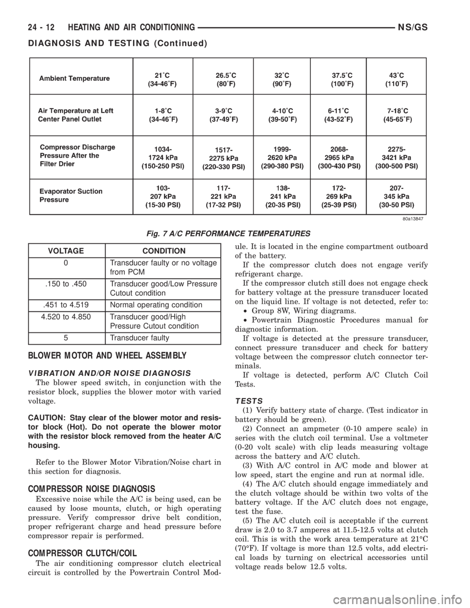
Fig. 7 A/C PERFORMANCE TEMPERATURES
VOLTAGE CONDITION
0 Transducer faulty or no voltage
from PCM
.150 to .450 Transducer good/Low Pressure
Cutout condition
.451 to 4.519 Normal operating condition
4.520 to 4.850 Transducer good/High
Pressure Cutout condition
5 Transducer faulty
24 - 12 HEATING AND AIR CONDITIONINGNS/GS
DIAGNOSIS AND TESTING (Continued)
Page 1883 of 1938
The use of R-134a will have a positive environmen-
tal impact due to it's zero ozone depletion and low
global warming impact.
CHARGING REFRIGERANT SYSTEM
CAUTION: Do not overcharge refrigerant system,
as excessive compressor head pressure can cause
noise and system failure.
After the system has been tested for leaks and
evacuated, a refrigerant (R-134a) charge can be
injected into the system.
NOTE: When connecting the service equipment
coupling to the line fitting, verify that the valve of
the coupling is fully closed. This will reduce the
amount of effort required to make the connection.
(1) Connect manifold gauge set.
(2) Measure refrigerant 0.96 kg (34 oz. or 2.13 lb.)
and heat to 52ÉC (125ÉF) with the charging station.
Refer to the instructions provided with the equip-
ment being used.
(3) Open the suction and discharge valves. Open
the charge valve to allow the heated refrigerant to
flow into the system. When the transfer of refriger-
ant has stopped, close the suction and discharge
valve.
(4) If all of the charge did not transfer from the
dispensing device, run engine at a high idle (1400
rpm). Set the A/C control to A/C, low blower speed,
and open windows. If the A/C compressor does not
engage, test the compressor clutch control circuit andcorrect any failure. Refer to Group 8W, Wiring Dia-
grams.
(5) Open the suction valve to allow the remaining
refrigerant to transfer to the system.
WARNING: TAKE CARE NOT TO OPEN THE DIS-
CHARGE (HIGH-PRESSURE) VALVE AT THIS TIME.
(6) Close all valves and test the A/C system perfor-
mance.
(7) Disconnect the charging station or manifold
gauge set. Install the service port caps.
EVACUATING REFRIGERANT SYSTEM
NOTE: Special effort must be used to prevent mois-
ture from entering the A/C system oil. Moisture in
the oil is very difficult to remove and will cause a
reliability problem with the compressor.
If a compressor designed to use R-134a refrigerant
is left open to the atmosphere for an extended period
of time. It is recommended that the refrigerant oil be
drained and replaced with new oil or a new compres-
sor be used. This will eliminate the possibility of con-
taminating the refrigerant system.
If the refrigerant system has been open to the
atmosphere, it must be evacuated before the system
can be filled. Moisture and air mixed with the refrig-
erant will raise the compressor head pressure above
acceptable operating levels. This will reduce the per-
formance of the air conditioner and damage the com-
pressor. Moisture will boil at near room temperature
when exposed to vacuum. To evacuate the refrigerant
system:
NOTE: When connecting the service equipment
coupling to the line fitting, verify that the valve of
the coupling is fully closed. This will reduce the
amount of effort required to make the connection.
(1) Connect a suitable charging station, refrigerant
recovery machine, or a manifold gauge set with vac-
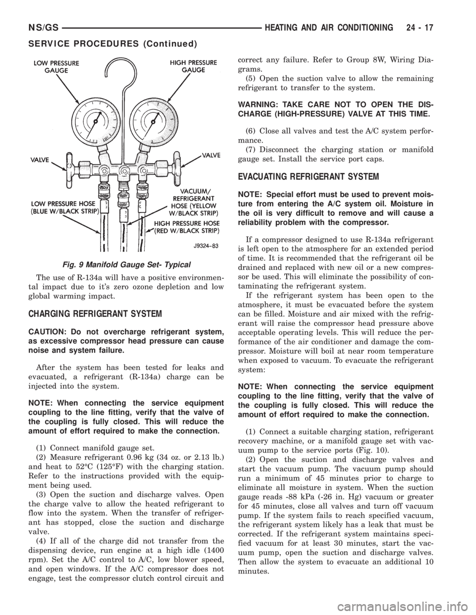
uum pump to the service ports (Fig. 10).
(2) Open the suction and discharge valves and
start the vacuum pump. The vacuum pump should
run a minimum of 45 minutes prior to charge to
eliminate all moisture in system. When the suction
gauge reads -88 kPa (-26 in. Hg) vacuum or greater
for 45 minutes, close all valves and turn off vacuum
pump. If the system fails to reach specified vacuum,
the refrigerant system likely has a leak that must be
corrected. If the refrigerant system maintains speci-
fied vacuum for at least 30 minutes, start the vac-
uum pump, open the suction and discharge valves.
Then allow the system to evacuate an additional 10
minutes.
Fig. 9 Manifold Gauge Set- Typical
NS/GSHEATING AND AIR CONDITIONING 24 - 17
SERVICE PROCEDURES (Continued)
Page 1886 of 1938
REMOVAL
(1) Disconnect the battery negative cable.
(2) Recover A/C system refrigerant.
(3) Unscrew the High Side service port from the
liquid line.
(4) Remove O-ring
INSTALLATION
For installation, reverse the above procedures.
²Install new O-ring.
²Evacuate and recharge A/C system.
BLEND-AIR DOOR ACTUATOR
REMOVAL
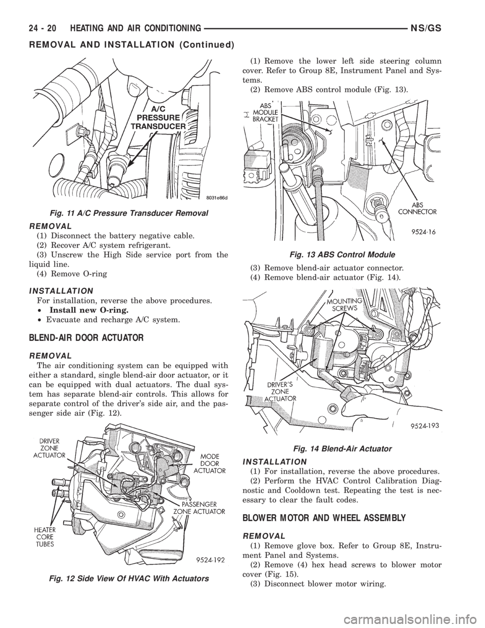
The air conditioning system can be equipped with
either a standard, single blend-air door actuator, or it
can be equipped with dual actuators. The dual sys-
tem has separate blend-air controls. This allows for
separate control of the driver's side air, and the pas-
senger side air (Fig. 12).(1) Remove the lower left side steering column
cover. Refer to Group 8E, Instrument Panel and Sys-
tems.
(2) Remove ABS control module (Fig. 13).
(3) Remove blend-air actuator connector.
(4) Remove blend-air actuator (Fig. 14).
INSTALLATION
(1) For installation, reverse the above procedures.
(2) Perform the HVAC Control Calibration Diag-
nostic and Cooldown test. Repeating the test is nec-
essary to clear the fault codes.
BLOWER MOTOR AND WHEEL ASSEMBLY
REMOVAL
(1) Remove glove box. Refer to Group 8E, Instru-
ment Panel and Systems.
(2) Remove (4) hex head screws to blower motor
cover (Fig. 15).
(3) Disconnect blower motor wiring.
Fig. 11 A/C Pressure Transducer Removal
Fig. 12 Side View Of HVAC With Actuators
Fig. 13 ABS Control Module
Fig. 14 Blend-Air Actuator
24 - 20 HEATING AND AIR CONDITIONINGNS/GS
REMOVAL AND INSTALLATION (Continued)
Page 1887 of 1938
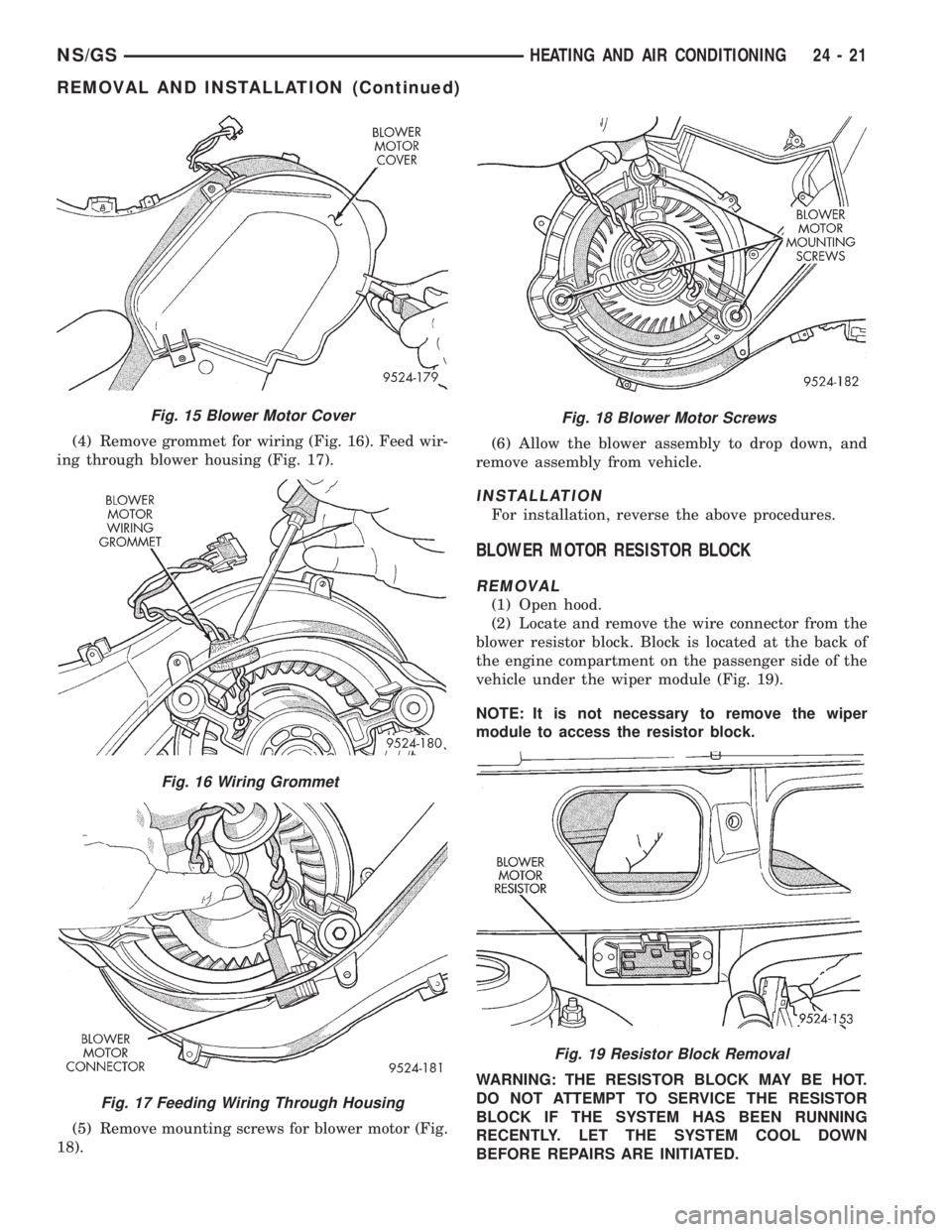
(4) Remove grommet for wiring (Fig. 16). Feed wir-
ing through blower housing (Fig. 17).
(5) Remove mounting screws for blower motor (Fig.
18).(6) Allow the blower assembly to drop down, and
remove assembly from vehicle.
INSTALLATION
For installation, reverse the above procedures.
BLOWER MOTOR RESISTOR BLOCK
REMOVAL
(1) Open hood.
(2) Locate and remove the wire connector from the
blower resistor block. Block is located at the back of
the engine compartment on the passenger side of the
vehicle under the wiper module (Fig. 19).
NOTE: It is not necessary to remove the wiper
module to access the resistor block.
WARNING: THE RESISTOR BLOCK MAY BE HOT.
DO NOT ATTEMPT TO SERVICE THE RESISTOR
BLOCK IF THE SYSTEM HAS BEEN RUNNING
RECENTLY. LET THE SYSTEM COOL DOWN
BEFORE REPAIRS ARE INITIATED.
Fig. 15 Blower Motor Cover
Fig. 16 Wiring Grommet
Fig. 17 Feeding Wiring Through Housing
Fig. 18 Blower Motor Screws
Fig. 19 Resistor Block Removal
NS/GSHEATING AND AIR CONDITIONING 24 - 21
REMOVAL AND INSTALLATION (Continued)
Page 1892 of 1938
(2) Hand-start the stud into the expansion valve
and torque to7-11N´m(64-96in.lbs.).
(3) Carefully install the expansion valve to the
sealing plate. Install the two screws and tighten 8 to
14 N´m (70 to 130 in. lbs.) torque.
(4) Carefully install the refrigerant lines and seal-
ing plate to the expansion valve. Install the nut and
tighten 20 to 26 N´m (170 to 230 in. lbs.) torque.
(5) Install the ground wire at dash panel.
(6) Pull generator back into the proper position for
bracket mounting.
(7) Install generator field wire connector.
(8) Install the upper generator bracket.
(9) Install accessory drive belt.
(10) Evacuate and recharge system.
(11) After expansion valve is installed, the system
is charged, and leaks have checked repeat the A/C
performance check.
FILTER-DRIER ASSEMBLY
REMOVAL
WARNING: THE REFRIGERATION SYSTEM MUST
BE COMPLETELY EMPTY BEFORE PROCEEDING
WITH THIS OPERATION.
(1) Recover A/C system refrigerant.
(2) Remove liquid line at filter-drier (Fig. 21).
(3) Remove the (2) bolts holding filter-drier bracket
to radiator fan module bracket.
(4) Remove the lower liquid line at condenser.
(5) Remove the upper radiator crossmember.
(6) Pull up on radiator and slide filter-drier from
the mounting location.
INSTALLATION
(1) Before installation, replace both refrigerant
line O-rings. Then reverse the above procedures.
(2) Evacuate and recharge system.
HEATER A/C UNIT HOUSING
REMOVAL
WARNING: IF EQUIPPED WITH AIR CONDITIONING,
THE REFRIGERATION SYSTEM MUST BE COM-
PLETELY EMPTY BEFORE PROCEEDING.
(1) Set parking brake.
(2) Disconnect battery negative cable.
(3) Using a refrigerant recovery machine, remove
refrigerant from the A/C system.
(4) Remove wiper module. Refer to Group 8K,
Windshield Wipers and Washers.
(5) Drain engine coolant. Remove heater hoses at
the heater core, refer to Heater Hoses Removal and
Installation procedures. Plug coolant lines.(6) Remove suction and liquid lines at the expan-
sion valve (Fig. 27).
(7) Remove the Instrument Panel Assembly. Refer
to Group 8E, Instrument Panel and Systems.
(8) Remove heater ducts.
(9) Disconnect the two upper mounts from the
upper reinforcement and the lower mount from the
tunnel.
(10) Remove the (3) nuts (in the engine compart-
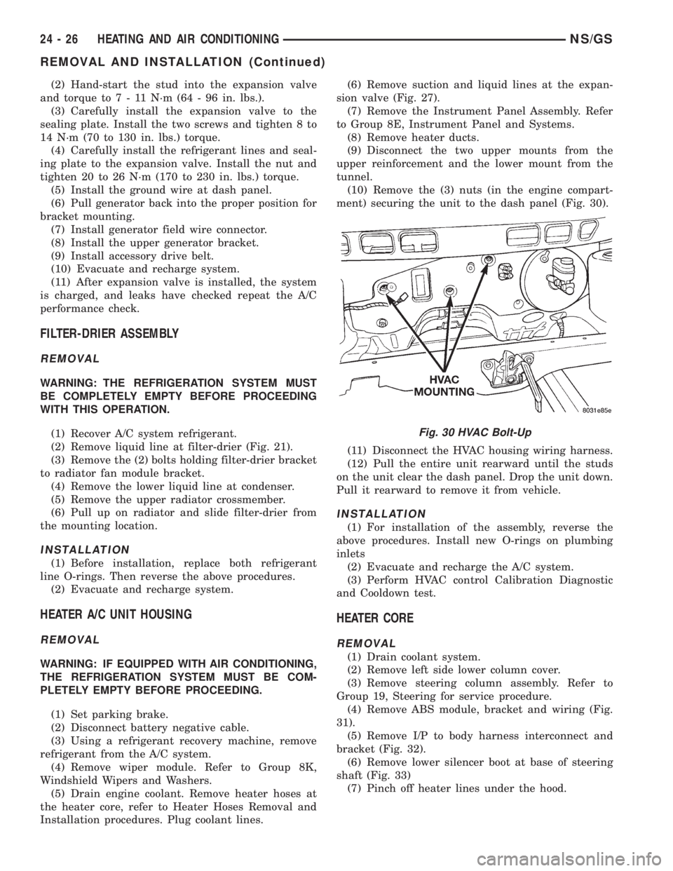
ment) securing the unit to the dash panel (Fig. 30).
(11) Disconnect the HVAC housing wiring harness.
(12) Pull the entire unit rearward until the studs
on the unit clear the dash panel. Drop the unit down.
Pull it rearward to remove it from vehicle.
INSTALLATION
(1) For installation of the assembly, reverse the
above procedures. Install new O-rings on plumbing
inlets
(2) Evacuate and recharge the A/C system.
(3) Perform HVAC control Calibration Diagnostic
and Cooldown test.
HEATER CORE
REMOVAL
(1) Drain coolant system.
(2) Remove left side lower column cover.
(3) Remove steering column assembly. Refer to
Group 19, Steering for service procedure.
(4) Remove ABS module, bracket and wiring (Fig.
31).
(5) Remove I/P to body harness interconnect and
bracket (Fig. 32).
(6) Remove lower silencer boot at base of steering
shaft (Fig. 33)
(7) Pinch off heater lines under the hood.
Fig. 30 HVAC Bolt-Up
24 - 26 HEATING AND AIR CONDITIONINGNS/GS
REMOVAL AND INSTALLATION (Continued)
Page 1897 of 1938
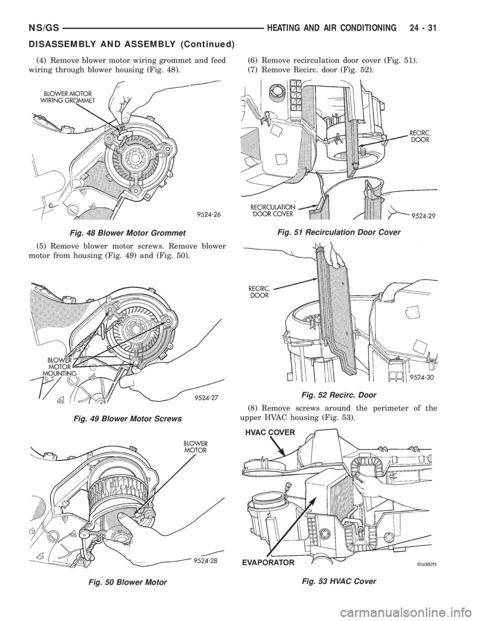
(4) Remove blower motor wiring grommet and feed
wiring through blower housing (Fig. 48).
(5) Remove blower motor screws. Remove blower
motor from housing (Fig. 49) and (Fig. 50).(6) Remove recirculation door cover (Fig. 51).
(7) Remove Recirc. door (Fig. 52).
(8) Remove screws around the perimeter of the
upper HVAC housing (Fig. 53).
Fig. 48 Blower Motor Grommet
Fig. 49 Blower Motor Screws
Fig. 50 Blower Motor
Fig. 51 Recirculation Door Cover
Fig. 52 Recirc. Door
Fig. 53 HVAC Cover
NS/GSHEATING AND AIR CONDITIONING 24 - 31
DISASSEMBLY AND ASSEMBLY (Continued)
Page 1907 of 1938
Adaptive Fuel Factor
Barometric Pressure
Engine Speed
Module Spark Advance
Speed Control Target
Intake Air Temp Degrees
Intake Air Temp Volts
Charging System Goal
Theft Alarm Status
Map Sensor Voltage
Vehicle Speed
Throttle Opening (percentage)
TPS Calculated
Cam Timing Position
Target Idle
Time From Start To Run
Run Time At Stall
Injector Pulse-width
Upstream O2S Volts
Downstream O2S Volts
Closed Loop Timer
Short Term Adaptive
Current Adaptive Cell
Adaptive Memory Cell 0
Adaptive Memory Cell 1
Adaptive Memory Cell 2
Adaptive Memory Cell 3
Adaptive Memory Cell 4
Adaptive Memory Cell 5
Adaptive Memory Cell 6
Adaptive Memory Cell 7
Adaptive Memory Cell 8
Adaptive Memory Cell 9
Adaptive Memory Cell 10
Adaptive Memory Cell 11
Adaptive Memory Cell 12
Adaptive Memory Cell 13
Adaptive Memory Cell 14
Adaptive Memory Cell 15
Purge Free Idle Cell
Purge Free Cell 2 (corresponds to memory cell 2)
Purge Free Cell 3 (corresponds to memory cell 5)
Target IAC Steps
Retard Cylinder (1)
Retard Cylinder (2)
Retard Cylinder (3)
Retard Cylinder (4)
Retard Cylinder (5)
Retard Cylinder (6)CIRCUIT ACTUATION TEST MODE
The Circuit Actuation Test Mode checks for proper
operation of output circuits or devices the Powertrain
Control Module (PCM) may not internally recognize.
The PCM attempts to activate these outputs and
allow an observer to verify proper operation. Most of
the tests provide an audible or visual indication of
device operation (click of relay contacts, fuel spray,
etc.). Except for intermittent conditions, if a device
functions properly during testing, assume the device,
its associated wiring, and driver circuit work cor-
rectly.
DIAGNOSTIC TROUBLE CODES
A Diagnostic Trouble Code (DTC) indicates the
PCM has recognized an abnormal condition in the
system.
The preferred and most accurate method of retriev-
ing a DTC is by using the DRB scan tool. The scan
tool supplies detailed diagnostic information which
can be used to more accurately diagnose causes for a
DTC.
Remember that DTC's are the results of a sys-
tem or circuit failure, but do not directly iden-
tify the failed component or components.
NOTE: For a list of DTC's, refer to the charts in this
section.
BULB CHECK
Each time the ignition key is turned to the ON
position, the malfunction indicator (check engine)
lamp on the instrument panel should illuminate for
approximately 2 seconds then go out. This is done for
a bulb check.
OBTAINING DTC'S USING DRB SCAN TOOL
(1) Connect the DRB scan tool to the data link
(diagnostic) connector. This connector is located in
the passenger compartment; at the lower edge of
instrument panel; near the steering column.
(2) Turn the ignition switch on and access the
ªRead Faultº screen.
(3) Record all the DTC's and ªfreeze frameº infor-
mation shown on the DRB scan tool.
(4) To erase DTC's, use the ªErase Trouble Codeº
data screen on the DRB scan tool.Do not erase any
DTC's until problems have been investigated
and repairs have been performed.
NSEMISSION CONTROL SYSTEMS 25 - 3
DESCRIPTION AND OPERATION (Continued)