1996 CHRYSLER VOYAGER instrument panel
[x] Cancel search: instrument panelPage 1870 of 1938
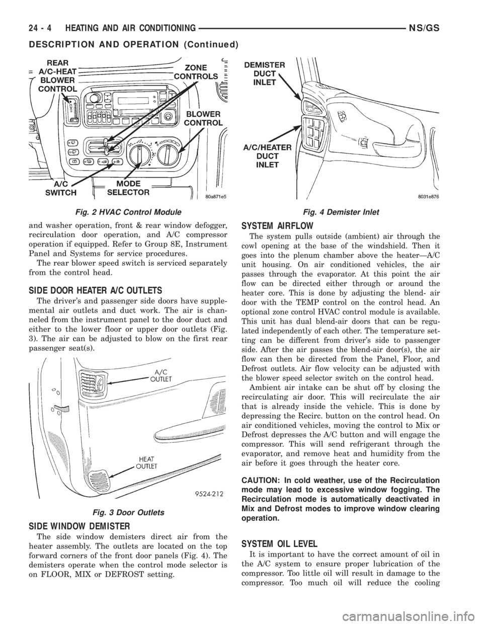
and washer operation, front & rear window defogger,
recirculation door operation, and A/C compressor
operation if equipped. Refer to Group 8E, Instrument
Panel and Systems for service procedures.
The rear blower speed switch is serviced separately
from the control head.
SIDE DOOR HEATER A/C OUTLETS
The driver's and passenger side doors have supple-
mental air outlets and duct work. The air is chan-
neled from the instrument panel to the door duct and
either to the lower floor or upper door outlets (Fig.
3). The air can be adjusted to blow on the first rear
passenger seat(s).
SIDE WINDOW DEMISTER
The side window demisters direct air from the
heater assembly. The outlets are located on the top
forward corners of the front door panels (Fig. 4). The
demisters operate when the control mode selector is
on FLOOR, MIX or DEFROST setting.
SYSTEM AIRFLOW
The system pulls outside (ambient) air through the
cowl opening at the base of the windshield. Then it
goes into the plenum chamber above the heaterÐA/C
unit housing. On air conditioned vehicles, the air
passes through the evaporator. At this point the air
flow can be directed either through or around the
heater core. This is done by adjusting the blend- air
door with the TEMP control on the control head. An
optional zone control HVAC control module is available.
This unit has dual blend-air doors that can be regu-
lated independently of each other. The temperature set-
ting can be different from driver's side to passenger
side. After the air passes the blend-air door(s), the air
flow can then be directed from the Panel, Floor, and
Defrost outlets. Air flow velocity can be adjusted with
the blower speed selector switch on the control head.
Ambient air intake can be shut off by closing the
recirculating air door. This will recirculate the air
that is already inside the vehicle. This is done by
depressing the Recirc. button on the control head. On
air conditioned vehicles, moving the control to Mix or
Defrost depresses the A/C button and will engage the
compressor. This will send refrigerant through the
evaporator, and remove heat and humidity from the
air before it goes through the heater core.
CAUTION: In cold weather, use of the Recirculation
mode may lead to excessive window fogging. The
Recirculation mode is automatically deactivated in
Mix and Defrost modes to improve window clearing
operation.
SYSTEM OIL LEVEL
It is important to have the correct amount of oil in
the A/C system to ensure proper lubrication of the
compressor. Too little oil will result in damage to the
compressor. Too much oil will reduce the cooling
Fig. 2 HVAC Control Module
Fig. 3 Door Outlets
Fig. 4 Demister Inlet
24 - 4 HEATING AND AIR CONDITIONINGNS/GS
DESCRIPTION AND OPERATION (Continued)
Page 1877 of 1938
²No charge
²Compressor not operating
Verify that the test was done with the evaporator
at room temperature. The test consists of starting
the compressor and measuring the time it takes for
the evaporator temperature to fall 7ÉC (20ÉF). If the
compressor has been running, the evaporator is cold
already and will not be capable of falling 7ÉC (20ÉF).
If the test was run with a cold evaporator, turn A/C
off and turn the blower motor switch to high position
for 3 to 5 minutes till the evaporator is to room tem-
perature. Then repeat the Calibration Diagnostic and
Cooldown test.
If refrigerant system is performing properly and
the system will not pass test. Repeat the Calibration
Diagnostic and Cooldown test to determine if the
evaporator temperature FIN sensor has developed an
open or a short circuit. If the HVAC control module
still passes Calibration test, verify Cooldown test
manually with a pocket thermometer. The outlet air
temperature must drop at least 7ÉC (20ÉF) within
two minutes. If the vehicle passes with the manual
thermometer, take HVAC control to level 4 (evapora-
tor probe temperature readout) and repeat the
Cooldown test. Ensure the evaporator is at room tem-
perature before starting test. Check if evaporator
probe will drop the temperature 7ÉC (20ÉF) in two
minutes. If the Evaporator Probe is found to be
faulty, check that the sensor is positioned in the
evaporator fins properly. If not, correct and repeat
test. If OK, replace the evaporator probe.
Once the repairs are completed, repeat the Calibra-
tion Diagnostic and Cooldown test. Repeating the
test is necessary to clear the fault codes.
A/C PERFORMANCE TEST
The air conditioning system is designed to remove
heat and humidity from the air entering the passen-
ger compartment. The evaporator, located in the
heater A/C unit, is cooled to temperatures near the
freezing point. As warm damp air passes over the
fins in the evaporator, moisture in the air condenses
to water, dehumidifying the air. Condensation on the
evaporator fins reduces the evaporators ability to
absorb heat. During periods of high heat and humid-
ity, an air conditioning system will be less effective.
With the instrument control set to RECIRC, only air
from the passenger compartment passes through the
evaporator. As the passenger compartment air dehu-
midifies, A/C performance levels rise.
PERFORMANCE TEST PROCEDURE
Review Safety Precautions and Warnings in this
group before proceeding with this procedure. Air tem-
perature in test room and on vehicle must be 21É C
(70ÉF) minimum for this test.
NOTE: When connecting the service equipment
coupling to the line fitting, verify that the valve of
the coupling is fully closed. This will reduce the
amount of effort required to make the connection.
(1) Connect a tachometer and manifold gauge set.
(2) Set control to A/C, RECIRC, and PANEL, tem-
perature lever on full cool and blower on high.
(3) Start engine and hold at 1000 rpm with A/C
clutch engaged.
(4) Engine should be warmed up with doors and
windows closed.
(5) Insert a thermometer in the left center A/C
outlet and operate the engine for five minutes. The
A/C clutch may cycle depending on ambient condi-
tions.
(6) With the A/C clutch engaged, compare the dis-
charge air temperature to the A/C Performance Tem-
peratures chart (Fig. 7).
(7) If the discharge air temperature fails to meet
the specifications in the performance temperature
chart. Refer to the Refrigerant Service Procedures for
further diagnosis.
A/C PRESSURE TRANSDUCER
The work area temperature must not be below
10ÉC (50ÉF) to test the compressor clutch circuit.
Before starting to test the transducer ensure that the
wire connector is clean of corrosion and connected
properly.
(1) With gear selector in park or neutral and park
brake set, start engine and allow to idle.
(2) Install scan tool (DRB):
²Go to main menu
²Select stand alone scan tool (DRB)
²Select refer to the proper year diagnostics
²Select climate control
²Select sensor display
²Select A/C high side volts
For A/C system to operate a voltage between .451
(Low Pressure Cutout) to 4.519 (High Pressure Cut-
out is required. Voltages outside this range indicate a
low or high pressure condition andwill notallow
the compressor to cycle.
The following chart denotes voltages and the
appropriate condition(s):
NS/GSHEATING AND AIR CONDITIONING 24 - 11
DIAGNOSIS AND TESTING (Continued)
Page 1881 of 1938

POSSIBLE LOCATIONS OR CAUSE OF
OBSTRUCTED COOLANT FLOW
(1) Pinched or kinked heater hoses.
(2) Improper heater hose routing.
(3) Plugged heater hoses or supply and return
ports at cooling system connections, refer to Group 7,
Cooling System.
(4) Plugged heater core.
(5) Air locked heater core.
(6) If coolant flow is verified and outlet tempera-
ture is insufficient, a mechanical problem may exist.
POSSIBLE LOCATION OR CAUSE OF
INSUFFICIENT HEAT
(1) Obstructed cowl air intake.
(2) Obstructed heater system outlets.
(3) Blend-air door not functioning properly.
TEMPERATURE CONTROL
If temperature cannot be adjusted with the TEMP
lever on the control panel, the following could require
service:
(1) Blend-air door binding.
(2) Faulty blend-air door motor.
(3) Improper engine coolant temperature.
(4) Faulty Instrument Panel Control.
SYSTEM CHARGE LEVEL TEST
The procedure below should be used to check
and/or fill the refrigerant charge in the air condition-
ing system.
NOTE: The amount of R134a refrigerant that the air
conditioning system holds is 0.96 kg (34 oz. or 2.13
lbs.).
NOTE: Low Charge, condition may be described
as:
²Loss of A/C performance
²Fog from A/C outlets
²evaporator may have a HISS sound
There are two different ways the system can be
tested:
²With a scan tool (DRB), thermocouple and the
Charge Determination Graph. Use the scan tool
(DRB) diagnostic topic: Engine±System Monitors, A/C
Pressure.
²Using a manifold gauge set, a thermocouple and
the Charge Determination Graph.
It is recommended to use the gauges or reclaim/re-
cycle equipment.
WARNING: AVOID BREATHING A/C REFRIGERANT
AND LUBRICANT VAPOR OR MIST. EXPOSURE MAY
IRRITATE EYES, NOSE AND THROAT. USE ONLY
APPROVED SERVICE EQUIPMENT MEETING SAEREQUIREMENTS TO DISCHARGE R-134a SYSTEM. IF
ACCIDENTAL SYSTEM DISCHARGE OCCURS, VEN-
TILATE WORK AREA BEFORE RESUMING SERVICE.
R-134a SERVICE EQUIPMENT OR VEHICLE A/C
SYSTEM SHOULD NOT BE PRESSURE TESTED OR
LEAK TESTED WITH COMPRESSED AIR. SOME
MIXTURES OF AIR/R-134a HAVE BEEN SHOWN TO
BE COMBUSTIBLE AT ELEVATED PRESSURES.
THESE MIXTURES ARE POTENTIALLY DANGER-
OUS AND MAY RESULT IN FIRE OR EXPLOSION
CAUSING INJURY OR PROPERTY DAMAGE.
(1) Establish your preferred method of measuring
liquid line pressure. Use a manifold gauge set or a
DRB scan tool.
(2) A
ttach a clamp-on thermocouple (Professional
Service Equipment 66-324-0014 or 80PK-1A) or equiv-
alent to the liquid line. It must be placed as close to
the A/C Pressure Transducer as possible to observe liq-
uid line temperature. Refer to ªThermocouple Probeº in
this section for more information on probe.
(3) The vehicle must be in the following modes:
²Transaxle in Park
²Engine Idling at 700 rpm
²A/C Controls Set to Outside Air
²Panel Mode
²Full Cool
²High Blower motor, (vehicle equipped with rear
A/C turn rear blower motor ON HIGH)
²A/C Button in the ON position
²Vehicle Windows Open.
²Recirc. button turned OFF
(4) Operate system for a couple of minutes to allow
the system to stabilize.
(5) Set system pressure to about 1793 kPa (260
psi) by placing a piece of cardboard over part of the
front side of the condenser. To place cardboard prop-
erly, remove the upper radiator-condenser cover.
Insert cardboard between condenser and radiator
front. This will maintain a constant pressure.
(6) Observe Liquid Line pressure and Liquid line
temperature. Using theCharge Determination
Chartdetermine where the system is currently oper-
ating. If the system is in the undercharged region,
ADD 0.057 Kg. (2 oz.) to the system and recheck
readings. If the system is in the overcharged region,
RECLAIM 0.057 Kg. (2 oz.) from the system and
recheck readings. Continue this process until the sys-
tem readings are in the proper charge area on the
Charge Determination Chart.
(7) The same procedure can be performed using
the scan tool (DRB). To determine liquid line pres-
sure, attach the scan tool, go to System Moni-
tors±A/C Pressure. Observe liquid line pressure from
A/C Pressure Transducer on digital display and digi-
tal thermometer. Refer toCharge Determination
Chartand determine where the system is operating.
NS/GSHEATING AND AIR CONDITIONING 24 - 15
DIAGNOSIS AND TESTING (Continued)
Page 1886 of 1938
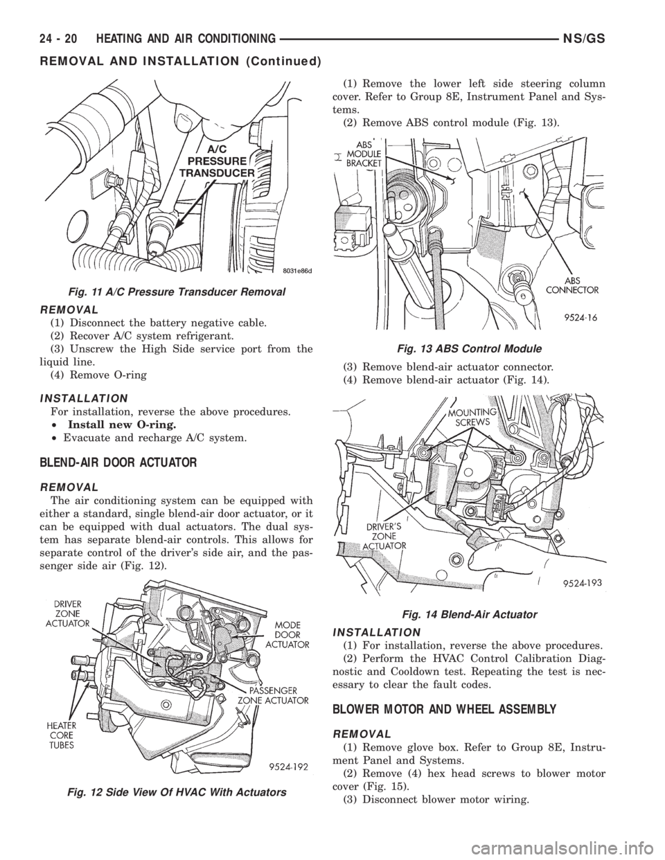
REMOVAL
(1) Disconnect the battery negative cable.
(2) Recover A/C system refrigerant.
(3) Unscrew the High Side service port from the
liquid line.
(4) Remove O-ring
INSTALLATION
For installation, reverse the above procedures.
²Install new O-ring.
²Evacuate and recharge A/C system.
BLEND-AIR DOOR ACTUATOR
REMOVAL
The air conditioning system can be equipped with
either a standard, single blend-air door actuator, or it
can be equipped with dual actuators. The dual sys-
tem has separate blend-air controls. This allows for
separate control of the driver's side air, and the pas-
senger side air (Fig. 12).(1) Remove the lower left side steering column
cover. Refer to Group 8E, Instrument Panel and Sys-
tems.
(2) Remove ABS control module (Fig. 13).
(3) Remove blend-air actuator connector.
(4) Remove blend-air actuator (Fig. 14).
INSTALLATION
(1) For installation, reverse the above procedures.
(2) Perform the HVAC Control Calibration Diag-
nostic and Cooldown test. Repeating the test is nec-
essary to clear the fault codes.
BLOWER MOTOR AND WHEEL ASSEMBLY
REMOVAL
(1) Remove glove box. Refer to Group 8E, Instru-
ment Panel and Systems.
(2) Remove (4) hex head screws to blower motor
cover (Fig. 15).
(3) Disconnect blower motor wiring.
Fig. 11 A/C Pressure Transducer Removal
Fig. 12 Side View Of HVAC With Actuators
Fig. 13 ABS Control Module
Fig. 14 Blend-Air Actuator
24 - 20 HEATING AND AIR CONDITIONINGNS/GS
REMOVAL AND INSTALLATION (Continued)
Page 1890 of 1938
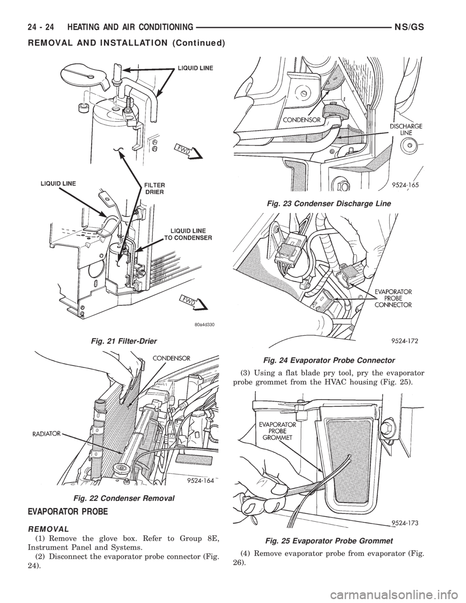
EVAPORATOR PROBE
REMOVAL
(1) Remove the glove box. Refer to Group 8E,
Instrument Panel and Systems.
(2) Disconnect the evaporator probe connector (Fig.
24).(3) Using a flat blade pry tool, pry the evaporator
probe grommet from the HVAC housing (Fig. 25).
(4) Remove evaporator probe from evaporator (Fig.
26).
Fig. 21 Filter-Drier
Fig. 22 Condenser Removal
Fig. 23 Condenser Discharge Line
Fig. 24 Evaporator Probe Connector
Fig. 25 Evaporator Probe Grommet
24 - 24 HEATING AND AIR CONDITIONINGNS/GS
REMOVAL AND INSTALLATION (Continued)
Page 1892 of 1938
(2) Hand-start the stud into the expansion valve
and torque to7-11N´m(64-96in.lbs.).
(3) Carefully install the expansion valve to the
sealing plate. Install the two screws and tighten 8 to
14 N´m (70 to 130 in. lbs.) torque.
(4) Carefully install the refrigerant lines and seal-
ing plate to the expansion valve. Install the nut and
tighten 20 to 26 N´m (170 to 230 in. lbs.) torque.
(5) Install the ground wire at dash panel.
(6) Pull generator back into the proper position for
bracket mounting.
(7) Install generator field wire connector.
(8) Install the upper generator bracket.
(9) Install accessory drive belt.
(10) Evacuate and recharge system.
(11) After expansion valve is installed, the system
is charged, and leaks have checked repeat the A/C
performance check.
FILTER-DRIER ASSEMBLY
REMOVAL
WARNING: THE REFRIGERATION SYSTEM MUST
BE COMPLETELY EMPTY BEFORE PROCEEDING
WITH THIS OPERATION.
(1) Recover A/C system refrigerant.
(2) Remove liquid line at filter-drier (Fig. 21).
(3) Remove the (2) bolts holding filter-drier bracket
to radiator fan module bracket.
(4) Remove the lower liquid line at condenser.
(5) Remove the upper radiator crossmember.
(6) Pull up on radiator and slide filter-drier from
the mounting location.
INSTALLATION
(1) Before installation, replace both refrigerant
line O-rings. Then reverse the above procedures.
(2) Evacuate and recharge system.
HEATER A/C UNIT HOUSING
REMOVAL
WARNING: IF EQUIPPED WITH AIR CONDITIONING,
THE REFRIGERATION SYSTEM MUST BE COM-
PLETELY EMPTY BEFORE PROCEEDING.
(1) Set parking brake.
(2) Disconnect battery negative cable.
(3) Using a refrigerant recovery machine, remove
refrigerant from the A/C system.
(4) Remove wiper module. Refer to Group 8K,
Windshield Wipers and Washers.
(5) Drain engine coolant. Remove heater hoses at
the heater core, refer to Heater Hoses Removal and
Installation procedures. Plug coolant lines.(6) Remove suction and liquid lines at the expan-
sion valve (Fig. 27).
(7) Remove the Instrument Panel Assembly. Refer
to Group 8E, Instrument Panel and Systems.
(8) Remove heater ducts.
(9) Disconnect the two upper mounts from the
upper reinforcement and the lower mount from the
tunnel.
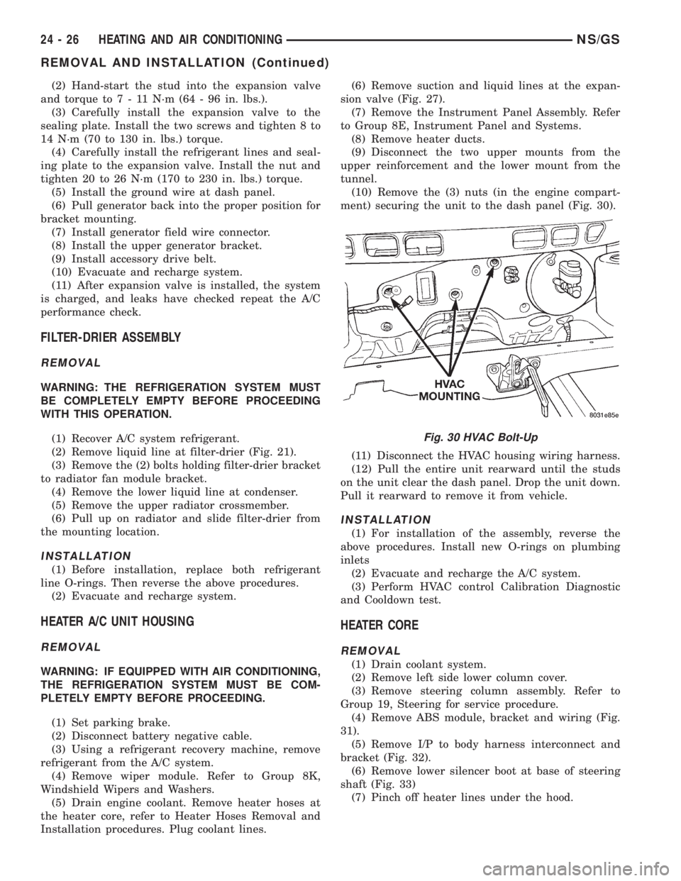
(10) Remove the (3) nuts (in the engine compart-
ment) securing the unit to the dash panel (Fig. 30).
(11) Disconnect the HVAC housing wiring harness.
(12) Pull the entire unit rearward until the studs
on the unit clear the dash panel. Drop the unit down.
Pull it rearward to remove it from vehicle.
INSTALLATION
(1) For installation of the assembly, reverse the
above procedures. Install new O-rings on plumbing
inlets
(2) Evacuate and recharge the A/C system.
(3) Perform HVAC control Calibration Diagnostic
and Cooldown test.
HEATER CORE
REMOVAL
(1) Drain coolant system.
(2) Remove left side lower column cover.
(3) Remove steering column assembly. Refer to
Group 19, Steering for service procedure.
(4) Remove ABS module, bracket and wiring (Fig.
31).
(5) Remove I/P to body harness interconnect and
bracket (Fig. 32).
(6) Remove lower silencer boot at base of steering
shaft (Fig. 33)
(7) Pinch off heater lines under the hood.
Fig. 30 HVAC Bolt-Up
24 - 26 HEATING AND AIR CONDITIONINGNS/GS
REMOVAL AND INSTALLATION (Continued)
Page 1895 of 1938
MODE DOOR ACTUATOR
REMOVAL
(1) Remove the lower left side steering column
cover. Refer to Group 8E, Instrument Panel and Sys-
tems.
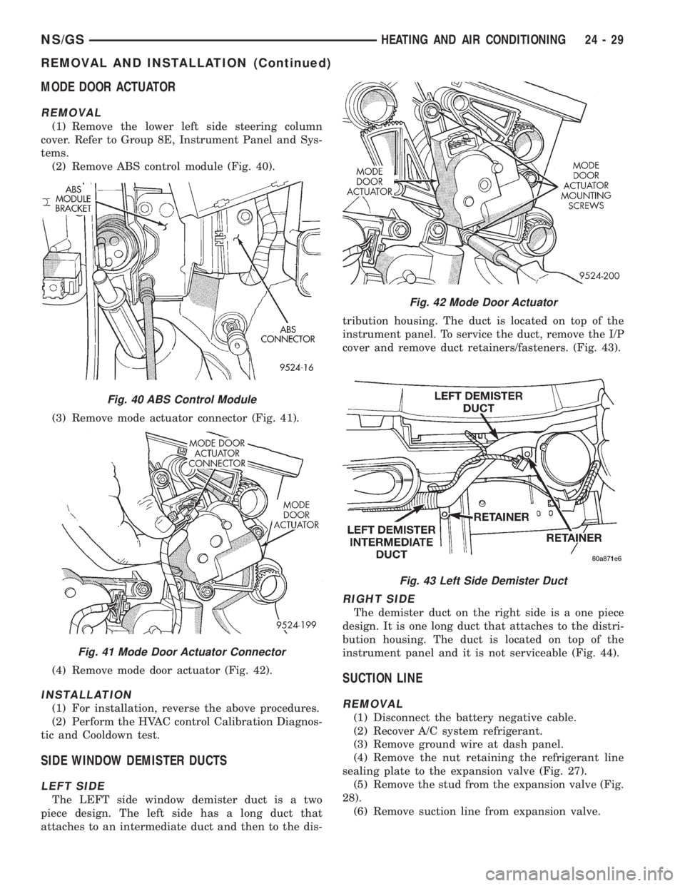
(2) Remove ABS control module (Fig. 40).
(3) Remove mode actuator connector (Fig. 41).
(4) Remove mode door actuator (Fig. 42).
INSTALLATION
(1) For installation, reverse the above procedures.
(2) Perform the HVAC control Calibration Diagnos-
tic and Cooldown test.
SIDE WINDOW DEMISTER DUCTS
LEFT SIDE
The LEFT side window demister duct is a two
piece design. The left side has a long duct that
attaches to an intermediate duct and then to the dis-tribution housing. The duct is located on top of the
instrument panel. To service the duct, remove the I/P
cover and remove duct retainers/fasteners. (Fig. 43).
RIGHT SIDE
The demister duct on the right side is a one piece
design. It is one long duct that attaches to the distri-
bution housing. The duct is located on top of the
instrument panel and it is not serviceable (Fig. 44).
SUCTION LINE
REMOVAL
(1) Disconnect the battery negative cable.
(2) Recover A/C system refrigerant.
(3) Remove ground wire at dash panel.
(4) Remove the nut retaining the refrigerant line
sealing plate to the expansion valve (Fig. 27).
(5) Remove the stud from the expansion valve (Fig.
28).
(6) Remove suction line from expansion valve.
Fig. 40 ABS Control Module
Fig. 41 Mode Door Actuator Connector
Fig. 42 Mode Door Actuator
Fig. 43 Left Side Demister Duct
NS/GSHEATING AND AIR CONDITIONING 24 - 29
REMOVAL AND INSTALLATION (Continued)
Page 1907 of 1938
Adaptive Fuel Factor
Barometric Pressure
Engine Speed
Module Spark Advance
Speed Control Target
Intake Air Temp Degrees
Intake Air Temp Volts
Charging System Goal
Theft Alarm Status
Map Sensor Voltage
Vehicle Speed
Throttle Opening (percentage)
TPS Calculated
Cam Timing Position
Target Idle
Time From Start To Run
Run Time At Stall
Injector Pulse-width
Upstream O2S Volts
Downstream O2S Volts
Closed Loop Timer
Short Term Adaptive
Current Adaptive Cell
Adaptive Memory Cell 0
Adaptive Memory Cell 1
Adaptive Memory Cell 2
Adaptive Memory Cell 3
Adaptive Memory Cell 4
Adaptive Memory Cell 5
Adaptive Memory Cell 6
Adaptive Memory Cell 7
Adaptive Memory Cell 8
Adaptive Memory Cell 9
Adaptive Memory Cell 10
Adaptive Memory Cell 11
Adaptive Memory Cell 12
Adaptive Memory Cell 13
Adaptive Memory Cell 14
Adaptive Memory Cell 15
Purge Free Idle Cell
Purge Free Cell 2 (corresponds to memory cell 2)
Purge Free Cell 3 (corresponds to memory cell 5)
Target IAC Steps
Retard Cylinder (1)
Retard Cylinder (2)
Retard Cylinder (3)
Retard Cylinder (4)
Retard Cylinder (5)
Retard Cylinder (6)CIRCUIT ACTUATION TEST MODE
The Circuit Actuation Test Mode checks for proper
operation of output circuits or devices the Powertrain
Control Module (PCM) may not internally recognize.
The PCM attempts to activate these outputs and
allow an observer to verify proper operation. Most of
the tests provide an audible or visual indication of
device operation (click of relay contacts, fuel spray,
etc.). Except for intermittent conditions, if a device
functions properly during testing, assume the device,
its associated wiring, and driver circuit work cor-
rectly.
DIAGNOSTIC TROUBLE CODES
A Diagnostic Trouble Code (DTC) indicates the
PCM has recognized an abnormal condition in the
system.
The preferred and most accurate method of retriev-
ing a DTC is by using the DRB scan tool. The scan
tool supplies detailed diagnostic information which
can be used to more accurately diagnose causes for a
DTC.
Remember that DTC's are the results of a sys-
tem or circuit failure, but do not directly iden-
tify the failed component or components.
NOTE: For a list of DTC's, refer to the charts in this
section.
BULB CHECK
Each time the ignition key is turned to the ON
position, the malfunction indicator (check engine)
lamp on the instrument panel should illuminate for
approximately 2 seconds then go out. This is done for
a bulb check.
OBTAINING DTC'S USING DRB SCAN TOOL
(1) Connect the DRB scan tool to the data link
(diagnostic) connector. This connector is located in
the passenger compartment; at the lower edge of
instrument panel; near the steering column.
(2) Turn the ignition switch on and access the
ªRead Faultº screen.
(3) Record all the DTC's and ªfreeze frameº infor-
mation shown on the DRB scan tool.
(4) To erase DTC's, use the ªErase Trouble Codeº
data screen on the DRB scan tool.Do not erase any
DTC's until problems have been investigated
and repairs have been performed.
NSEMISSION CONTROL SYSTEMS 25 - 3
DESCRIPTION AND OPERATION (Continued)