1996 CHRYSLER VOYAGER instrument panel
[x] Cancel search: instrument panelPage 1471 of 1938
(23) Install the 3 bolts (1 in each spoke of the
steering wheel) attaching the air bag module to the
steering wheel. Tighten the 3 air bag module attach-
ing nuts to a torque of 11 N´m (100 in. lbs.).
(24) Install the steering column cover liner (Fig. 4)
on the lower instrument panel. Install and securely
tighten the 10 bolts (Fig. 4) attaching the steering
column cover liner to the instrument panel.
(25) Install the park brake pedal release cable on
the park brake release lever in the lower steering col-
umn cover (Fig. 3).
(26) Install the lower steering column trim panel
on the lower instrument panel. Install and securely
the screws attaching the lower steering column cover
to the instrument panel (Fig. 2).
(27) Connect negative (ground) cable on the bat-
tery terminal.SPECIFICATIONS
STEERING COLUMN FASTENER TORQUE
SPECIFICATIONS
DESCRIPTION TORQUE
STEERING WHEEL:
Retaining Nut...............61N´m(45ft.lbs.)
STEERING COLUMN ASSEMBLY:
Mounting Bracket
Attaching Nuts............12N´m(105 in. lbs.)
Flex Coupler Pinch Bolt.......27N´m(240 in. lbs.)
Airbag Module Attaching Nuts . .11 N´m (100 in. lbs.)
NSSTEERING 19 - 45
REMOVAL AND INSTALLATION (Continued)
Page 1548 of 1938
TORQUE MANAGEMENT
Most 41TE transaxles utilize torque management.
Torque management is a unique function of the Pow-
ertrain Control Module (PCM). The PCM receives
output signals from the Transmission Control Module
(TCM) and many various engine sensors. The PCM
evaluates these signals and decides if it is necessary
to decrease the output of the engine's torque. This
reduction in torque does not interfere with the nor-
mal operation of the vehicle. This reduction in torque
will prolong the life of the drivetrain components.
Torque reduction is not noticeable in normal driving
functions. The torque reduction function shuts off
above 16 MPH.
ON-BOARD DIAGNOSTICS
This vehicle utilizes a diagnostic system called
OBDII. The powertrain control module communicates
with the Transmission Control Module. Whenever
the transaxle sets a fault in the Transmission Con-
trol Module (dependent on which fault is set), the
powertrain control module will turn on a MIL (Mal-
function Indicator Lamp) on the instrument cluster.
By reading the code in the powertrain control module
it will tell you where the fault occurred. If the fault
occurred in the transaxle, the controller will read a
CODE 45.For further information regarding OBDII,
refer to Group 25, Emission Systems.
These controls provide comprehensive, on-board
transaxle diagnostics. The information available can
aid in transaxle diagnosis. For example, apply ele-
ment buildup rate indicates solenoid performance.
Also included are self diagnostic functions. Self diag-
nostics allow the technician to test the condition of
the electronic controls. The Transmission Control
Module continuously monitors its critical functions. It
also records any malfunctions, and the number of
engine starts since the last malfunction. This allows
the technician to use the information in the event of
a customer complaint.
TRANSMISSION CONTROL MODULE
Do not interchange Transmission Control Modules
with previous year transmission control modules. If a
same year TCM is being used from a different vehi-
cle, the following procedures must be performed:
²Quick Learn Procedure
²Electronic Pinion Factor Procedure
The Transmission Control Module is located on the
right inner fender panel, in the engine compartment.
It is held in place by four mounting screws.NOTE: If the Transmission Control Module has
been replaced, the following procedures must be
performed:
²Quick Learn Procedure: This procedure will
allow the transmission control module to learn the
characteristics of the vehicle.
²Electronic Pinion Factor Procedure: This proce-
dure will reprogram the TCM to compensate for dif-
ferent tire sizes and final drive ratios.
GEARSHIFT AND PARKING LOCK CONTROLS
The transaxle is controlled by a lever type gear-
shift incorporated within the steering column. The
control has six selector lever positions: P (park), R
(reverse), N (neutral), and D (drive), 2 (second), and
1 (first). The parking lock is applied by moving the
selector lever past a gate to the P position.Do not
apply the parking lock until the vehicle has
stopped; otherwise, a severe ratchet noise will
occur.
TRANSMISSION RANGE SENSOR
The 41TE transaxle is equipped with a transmis-
sion range sensor that is located on top of the valve
body. This sensor will allow for accurate transmission
gear position measurement.
To service the transmission range sensor (TRS),
you must remove the valve body. For repair proce-
dures, refer to the Removal and Installation section
within this group.
Also located within the TRS is a transmission tem-
perature sensor. This sensor is used to measure the
transmission fluid sump temperature. The transmis-
sion temperature sensor is serviced with the TRS as
a unit.
SHIFT POSITION INDICATOR
The shifter position indicator is located in the
instrument cluster. The shifter position indicator out-
lines with a box the gear position the transaxle man-
ual valve lever is in.
The transmission range sensor (located on the
valvebody) sends a signal to the TCM on the position
of the transaxle manual valve lever. The TCM
receives the switch signal and processes the data.
The TCM sends the Shift Lever Position (SLP) infor-
mation to the BCM via the CCD bus. The BCM then
outlines with a box the appropriate shifter position
indicator in the instrument cluster.
To replace the shifter position indicator, refer to
Group 8E, Instrument Panel And Gauges.
21 - 74 TRANSAXLE AND POWER TRANSFER UNITNS
DESCRIPTION AND OPERATION (Continued)
Page 1553 of 1938
If a problem arises with the shifter position indica-
tor, consult the following chart for diagnostic infor-
mation. If the malfunction cannot be corrected using
the chart, consult the proper diagnostic manual.
To replace the shifter position indicator, refer to
Group 8E, Instrument Panel And Gauges.SERVICE PROCEDURES
FLUID AND FILTER CHANGE
When the factory fill fluid is changed, only fluids
labeled MOPARtATF PLUS 3 (Automatic Transmis-
sion fluid) Type 7176 should be used.
If the transaxle is disassembled for any reason, the
fluid and filter should be changed.
30,000 MILE TRANSAXLE OIL CHANGE
When a vehicle attains 30,000 miles on its odome-
ter it is recommended that the transaxle oil be
changed. To change the oil, use the procedure that
follows:
It is recommended that a transaxle fluid exchanger
(ATF 2000+ or equivalent) be used to replace the
used fluid in the transaxle. If a fluid exchanger is not
available use a fluid suction pump (Vaculayor equiv-
alent) to draw the fluid out of the dipstick tube. If a
fluid suction pump is not available remove the oil
pan and drain the fluid.
CAUTION: Chrysler Corporation does not recom-
mend using any fluid exchanger that introduces
additives into the transaxle.
TRANSAXLE FLUID EXCHANGER METHOD
(1) To perform the transaxle fluid exchange, the
transaxle must be at operating temperature. Drive
the vehicle till it reaches full operating temperature.
(2) Verify that the fill tank on the transaxle fluid
exchanger (ATF 2000+ or equivalent) is clean and
dry.
(3) Fill the tank to the recommended fill capacity
with Mopar ATF Plus 3 Type 7176.
(4) Hookup the vehicle to the machine following
the manufacturers instructions. Perform the
exchange procedure following the instructions pro-
vided with the machine.
(5) Once machine has completed the fluid
exchange. Check the fluid level and condition and fill
to proper level with Mopar ATF Plus 3 Type 7176.
NOTE: Verify that the transaxle cooler lines are
tightened to proper specifications. Cooler line
torque specification is 2 N´m (18 in. lbs.).
CONDITION POSSIBLE CAUSE
ALL PRND3L DISPLAY
LIGHTS9ON9IN P&N
GEAR POSITIONS1.Check wiring and
connectors
2. Faulty trans. range
sensor
3. Faulty manual lever
ALL DISPLAY LIGHTS
9ON9IN ALL GEAR
POSITIONS1. Check wiring &
connectors
2. Faulty trans. range
sensor
3. Faulty manual lever
4. CCD communication
malfunction
5. Check oil level
ALL DISPLAY LIGHTS
9OFF91. Normal transient
condition between P&R
and R&N gear positions
2. Check shift lever
linkage
3. Body controller
malfunction
4. Check wiring and
connectors
5. Faulty cluster
ALL DISPLAY LIGHTS
9OFF9ACCOMPANIED
BY A9NO BUS9
MESSAGE1. CCD communication
malfunction
DISPLAY LIGHTS OUT
OF SEQUENCE WITH
SHIFT LEVER1. Check wiring and
connectors
2. Faulty trans. range
sensor
3. Faulty manual lever
4. CCD communication
malfunction
NSTRANSAXLE AND POWER TRANSFER UNIT 21 - 79
DIAGNOSIS AND TESTING (Continued)
Page 1557 of 1938
²The shift lever position must stay until
prompted to shift to overdrive
²The shift lever position must stay in overdrive
after the Shift to Overdrive prompt until the DRBIII
indicates the procedure is complete
²The calculated oil temperature must be above
60É and below 200É
(1) Plug the DRBIII scan tool into the data link
connector. The connector is located under the instru-
ment panel.
(2) Go to the Transmission screen.
(3) Go to the Miscellaneous screen.
(4) Select Quick Learn Procedure. Follow the
instructions of the DRBIII to perform the Quick
Learn Procedure.
PINION FACTOR PROCEDURE
The vehicle speed readings for the speedometer are
taken from the output speed sensor. The TCM must
be calibrated to the different combinations of equip-
ment available. A procedure has been developed
called Pinion Factor. It allows the technician to set
the Transmission Control Module initial setting so
that the speedometer readings will be correct.
Failure to perform this procedure will cause a No
Speedometer Operation condition.
This procedure must be performed if the Transmis-
sion Control Module has been replaced.
To properly read or reset the Pinion Factor, it is
necessary to use a DRBIII scan tool. Perform the fol-
lowing steps with the DRBIII scan tool to read or
reset the Pinion Factor:
(1) Plug the DRBIII scan tool into the data link
connector located under the instrument panel.
(2) Select the Transmission menu.
(3) Select the Miscellaneous menu.
(4) Select Pinion Factor. Then follow the instruc-
tions on the DRBIII scan tool screen.
REMOVAL AND INSTALLATION
GEARSHIFT CABLE
REMOVAL
(1) Remove cable eyelet attachment from transaxle
operating lever pin (Fig. 6).
(2) Using pliers, squeeze ears of cable conduit
attachment at mounting bracket (Fig. 7) and push
through hole to remove (Fig. 8).
(3) Remove the under instrument panel silencer
(Fig. 9). Refer to Group 8E, Instrument Panel And
Gauges for more information.
(4) At the steering column attachment, remove the
cable eyelet attachment from the shift lever pin.(5) Using pliers, squeeze ears of cable attachment
at mounting bracket then push through hole to
remove.
(6) Unseat the dash grommet and remove the
cable from the vehicle.
INSTALLATION
(1) Install cable into steering column attachment
bracket. Verify conduit ears are fully engaged. Verify
cable does not interfere with brake pedal actuation.
(2) Attach cable eyelet fitting onto shift lever pin.
(3) Insert transaxle end of cable through dash
panel hole and fully seat grommet.
(4) Install instrument panel silencer. Verify gear-
shift cable is routed through the slot in the silencer.
CAUTION: Failure to route the cable properly at the
silencer may cause brake pedal interference.
(5) Attach transaxle end of cable to the mounting
bracket on the transaxle. Assure the conduit attach-
ment ears are fully seated.
Fig. 6 Gearshift Cable
Fig. 7 Grommet Clips
NSTRANSAXLE AND POWER TRANSFER UNIT 21 - 83
SERVICE PROCEDURES (Continued)
Page 1558 of 1938
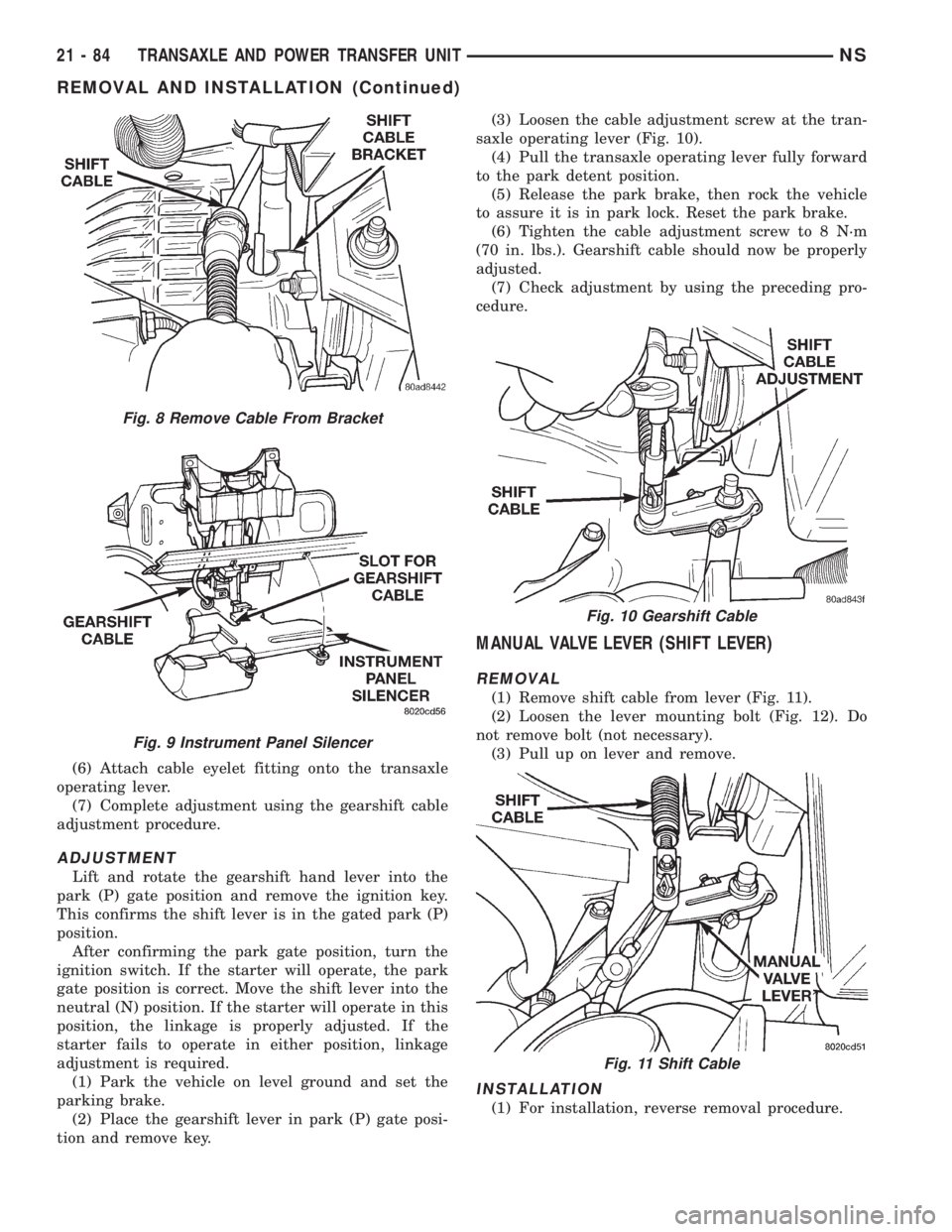
(6) Attach cable eyelet fitting onto the transaxle
operating lever.
(7) Complete adjustment using the gearshift cable
adjustment procedure.
ADJUSTMENT
Lift and rotate the gearshift hand lever into the
park (P) gate position and remove the ignition key.
This confirms the shift lever is in the gated park (P)
position.
After confirming the park gate position, turn the
ignition switch. If the starter will operate, the park
gate position is correct. Move the shift lever into the
neutral (N) position. If the starter will operate in this
position, the linkage is properly adjusted. If the
starter fails to operate in either position, linkage
adjustment is required.
(1) Park the vehicle on level ground and set the
parking brake.
(2) Place the gearshift lever in park (P) gate posi-
tion and remove key.(3) Loosen the cable adjustment screw at the tran-
saxle operating lever (Fig. 10).
(4) Pull the transaxle operating lever fully forward
to the park detent position.
(5) Release the park brake, then rock the vehicle
to assure it is in park lock. Reset the park brake.
(6) Tighten the cable adjustment screw to 8 N´m
(70 in. lbs.). Gearshift cable should now be properly
adjusted.
(7) Check adjustment by using the preceding pro-
cedure.
MANUAL VALVE LEVER (SHIFT LEVER)
REMOVAL
(1) Remove shift cable from lever (Fig. 11).
(2) Loosen the lever mounting bolt (Fig. 12). Do
not remove bolt (not necessary).
(3) Pull up on lever and remove.
INSTALLATION
(1) For installation, reverse removal procedure.
Fig. 8 Remove Cable From Bracket
Fig. 9 Instrument Panel Silencer
Fig. 10 Gearshift Cable
Fig. 11 Shift Cable
21 - 84 TRANSAXLE AND POWER TRANSFER UNITNS
REMOVAL AND INSTALLATION (Continued)
Page 1734 of 1938
STATIONARY GLASS
INDEX
page page
DESCRIPTION AND OPERATION
SAFETY PRECAUTIONS................... 4
REMOVAL AND INSTALLATION
BODY SIDE/SLIDING DOOR STATIONARY
GLASS............................... 6REAR WINDOW.......................... 7
WINDSHIELD............................ 4
DESCRIPTION AND OPERATION
SAFETY PRECAUTIONS
WARNING: DO NOT OPERATE THE VEHICLE
WITHIN 24 HOURS OF WINDSHIELD INSTALLATION.
IT TAKES AT LEAST 24 HOURS FOR URETHANE
ADHESIVE TO CURE. IF IT IS NOT CURED, THE
WINDSHIELD MAY NOT PERFORM PROPERLY IN
AN ACCIDENT.
URETHANE ADHESIVES ARE APPLIED AS A SYS-
TEM. USE GLASS CLEANER, GLASS PREP SOL-
VENT, GLASS PRIMER, PVC (VINYL) PRIMER AND
PINCHWELD (FENCE) PRIMER PROVIDED BY THE
ADHESIVE MANUFACTURER. IF NOT, STRUCTURAL
INTEGRITY COULD BE COMPROMISED.
CHRYSLER DOES NOT RECOMMEND GLASS
ADHESIVE BY BRAND. TECHNICIANS SHOULD
REVIEW PRODUCT LABELS AND TECHNICAL DATA
SHEETS, AND USE ONLY ADHESIVES THAT THEIR
MANUFACTURES WARRANT WILL RESTORE A
VEHICLE TO THE REQUIREMENTS OF FMVSS 212.
TECHNICIANS SHOULD ALSO INSURE THAT PRIM-
ERS AND CLEANERS ARE COMPATIBLE WITH THE
PARTICULAR ADHESIVE USED.
BE SURE TO REFER TO THE URETHANE MANU-
FACTURER'S DIRECTIONS FOR CURING TIME
SPECIFICATIONS, AND DO NOT USE ADHESIVE
AFTER ITS EXPIRATION DATE.
VAPORS THAT ARE EMITTED FROM THE URE-
THANE ADHESIVE OR PRIMER COULD CAUSE
PERSONAL INJURY. USE THEM IN A WELL-VENTI-
LATED AREA.
SKIN CONTACT WITH URETHANE ADHESIVE
SHOULD BE AVOIDED. PERSONAL INJURY MAY
RESULT.
ALWAYS WEAR EYE AND HAND PROTECTION
WHEN WORKING WITH GLASS.
CAUTION: Protect all painted and trimmed surfaces
from coming in contact with urethane or primers.Be careful not to damage painted surfaces when
removing moldings or cutting urethane around
windshield.
It is difficult to salvage a windshield during the
removal operation. The windshield is part of the
structural support for the roof. The urethane bonding
used to secure the windshield to the fence is difficult
to cut or clean from any surface. If the moldings are
set in urethane, it would also be unlikely they could
be salvaged. Before removing the windshield, check
the availability of the windshield and moldings from
the parts supplier.
REMOVAL AND INSTALLATION
WINDSHIELD
The urethane adhesive holding the windshield to
the opening pinch weld (fence) can be cut using a
sharp cold knife from the exterior of the vehicle.
Using the cold knife method is effective if the wind-
shield is already broken. If the glass must be sal-
vaged, cutting the urethane adhesive from the
interior of the vehicle using a reciprocating or oscil-
lating power knife is recommended.
WINDSHIELD REMOVAL ± EXTERIOR METHOD
(1) Remove inside rear view mirror.
(2) Remove windshield wiper arms.
(3) Remove cowl cover.
(4) Remove A-pillar trim panels.
(5) Disconnect wire connectors to windshield
defroster grid.
(6) Place protective covers over instrument panel
and hood.
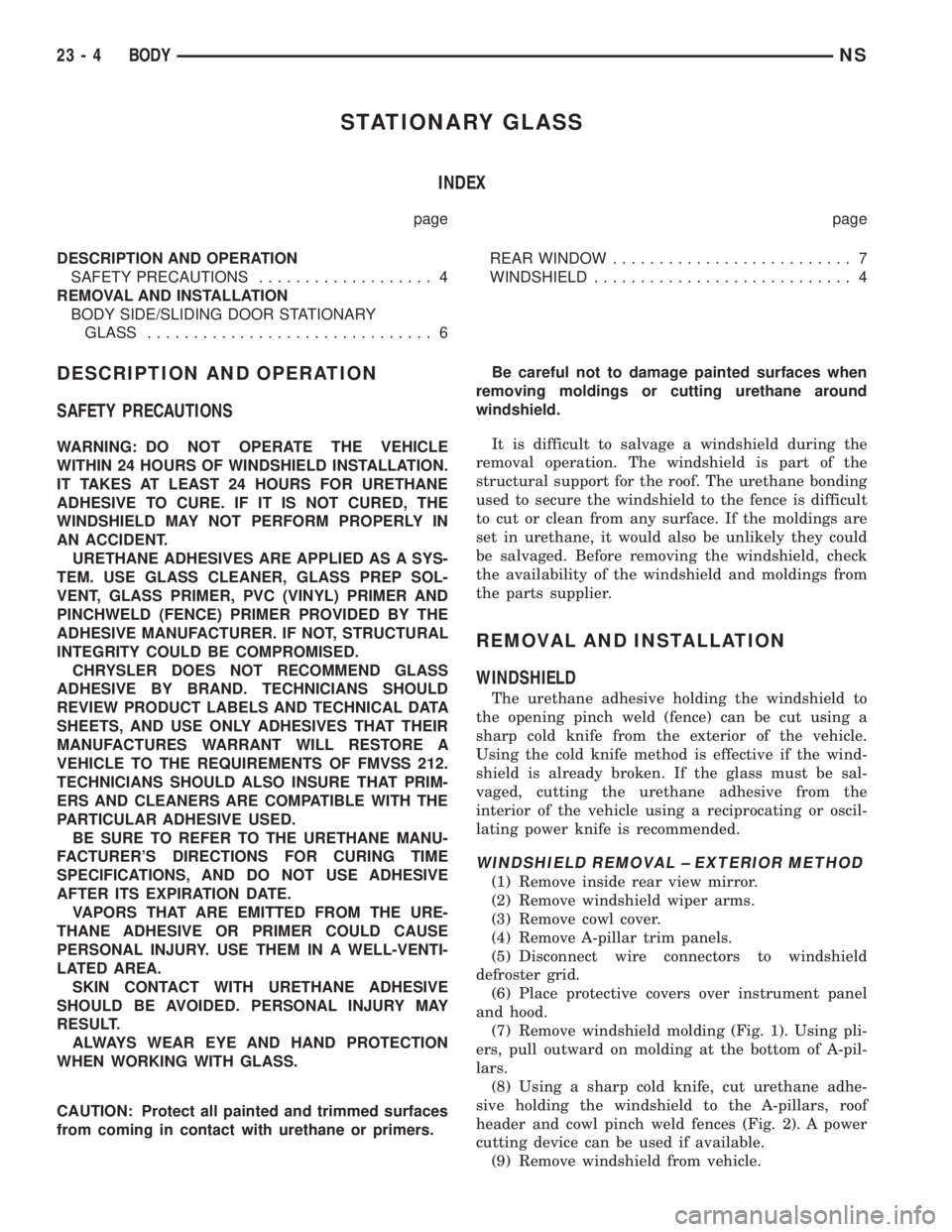
(7) Remove windshield molding (Fig. 1). Using pli-
ers, pull outward on molding at the bottom of A-pil-
lars.
(8) Using a sharp cold knife, cut urethane adhe-
sive holding the windshield to the A-pillars, roof
header and cowl pinch weld fences (Fig. 2). A power
cutting device can be used if available.
(9) Remove windshield from vehicle.
23 - 4 BODYNS
Page 1735 of 1938
WINDSHIELD REMOVAL ± INTERIOR METHOD
(1) Remove inside rear view mirror.
(2) Remove instrument panel top cover. Refer to
Group 8E, Instrument Panel and Systems.
(3) Remove A-pillar trim covers.
(4) Disconnect wire connectors to windshield
defroster grid.
(5) Place protective covers over instrument panel
and hood.
(6) Using a reciprocating or oscillating power
knife, cut urethane adhesive holding the windshield
to the A-pillars, roof header and cowl pinch weld
fences. Refer to instructions provided with the equip-
ment being used.
(7) Remove windshield from vehicle.
WINDSHIELD INSTALLATION
CAUTION: Open the left front door glass before
installing windshield to avoid pressurizing the pas-
senger compartment. If a door is slammed before
urethane bonding is cured, water leaks can result.
Allow the urethane at least 24 hours to cure
before returning the vehicle to use.
To avoid stressing the replacement windshield,
the urethane bonding material on the windshield
fence should be smooth and consistent to theshape of the replacement windshield. The support
spacers should be cleaned and properly installed
on weld studs or repair screws at bottom of wind-
shield opening.
(1) Place replacement windshield into windshield
opening and position glass in the center of the open-
ing against the support spacers.
(2) Verify the glass lays evenly against the pinch
weld fence at the sides, top and bottom of the
replacement windshield. If not, the pinch weld fence
must be formed to the shape of the new glass.
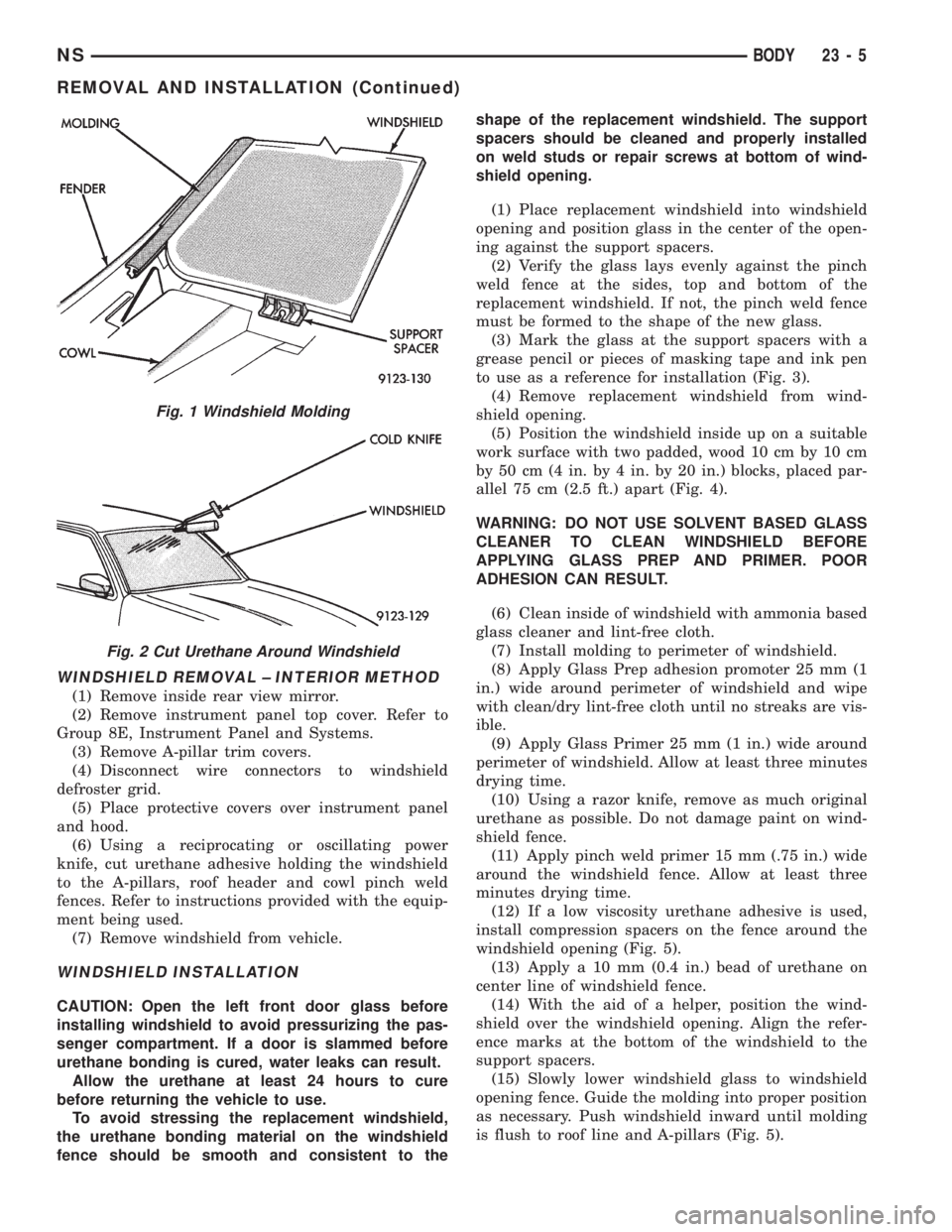
(3) Mark the glass at the support spacers with a
grease pencil or pieces of masking tape and ink pen
to use as a reference for installation (Fig. 3).
(4) Remove replacement windshield from wind-
shield opening.
(5) Position the windshield inside up on a suitable
work surface with two padded, wood 10 cm by 10 cm
by 50 cm (4 in. by 4 in. by 20 in.) blocks, placed par-
allel 75 cm (2.5 ft.) apart (Fig. 4).
WARNING: DO NOT USE SOLVENT BASED GLASS
CLEANER TO CLEAN WINDSHIELD BEFORE
APPLYING GLASS PREP AND PRIMER. POOR
ADHESION CAN RESULT.
(6) Clean inside of windshield with ammonia based
glass cleaner and lint-free cloth.
(7) Install molding to perimeter of windshield.
(8) Apply Glass Prep adhesion promoter 25 mm (1
in.) wide around perimeter of windshield and wipe
with clean/dry lint-free cloth until no streaks are vis-
ible.
(9) Apply Glass Primer 25 mm (1 in.) wide around
perimeter of windshield. Allow at least three minutes
drying time.
(10) Using a razor knife, remove as much original
urethane as possible. Do not damage paint on wind-
shield fence.
(11) Apply pinch weld primer 15 mm (.75 in.) wide
around the windshield fence. Allow at least three
minutes drying time.
(12) If a low viscosity urethane adhesive is used,
install compression spacers on the fence around the
windshield opening (Fig. 5).
(13) Apply a 10 mm (0.4 in.) bead of urethane on
center line of windshield fence.
(14) With the aid of a helper, position the wind-
shield over the windshield opening. Align the refer-
ence marks at the bottom of the windshield to the
support spacers.
(15) Slowly lower windshield glass to windshield
opening fence. Guide the molding into proper position
as necessary. Push windshield inward until molding
is flush to roof line and A-pillars (Fig. 5).
Fig. 1 Windshield Molding
Fig. 2 Cut Urethane Around Windshield
NSBODY 23 - 5
REMOVAL AND INSTALLATION (Continued)
Page 1755 of 1938
may be necessary to use a soldering gun to melt
the newly applied material. Do not over heat the
affected area, damage to the exterior of the trim
panel may occur.
(4) Allow the repaired area to cool and verify the
repair.
(5) Install trim panel.
REMOVAL AND INSTALLATION
A-PILLAR LOWER EXTENSION TRIM
REMOVAL
(1) Remove instrument panel side cover.
(2) Remove screw holding A-pillar extension to
door hinge pillar.
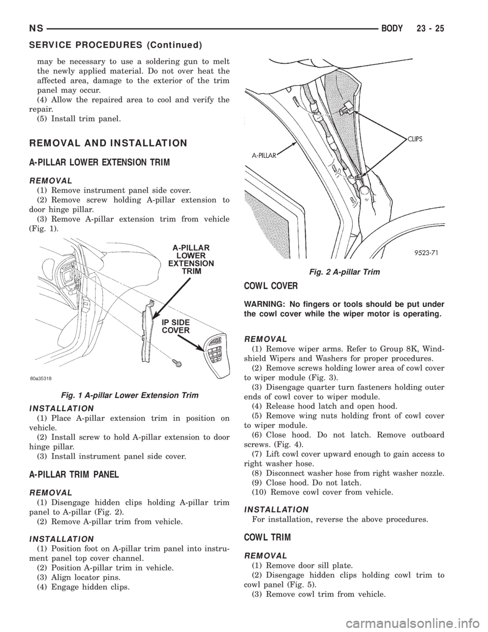
(3) Remove A-pillar extension trim from vehicle
(Fig. 1).
INSTALLATION
(1) Place A-pillar extension trim in position on
vehicle.
(2) Install screw to hold A-pillar extension to door
hinge pillar.
(3) Install instrument panel side cover.
A-PILLAR TRIM PANEL
REMOVAL
(1) Disengage hidden clips holding A-pillar trim
panel to A-pillar (Fig. 2).
(2) Remove A-pillar trim from vehicle.
INSTALLATION
(1) Position foot on A-pillar trim panel into instru-
ment panel top cover channel.
(2) Position A-pillar trim in vehicle.
(3) Align locator pins.
(4) Engage hidden clips.
COWL COVER
WARNING: No fingers or tools should be put under
the cowl cover while the wiper motor is operating.
REMOVAL
(1) Remove wiper arms. Refer to Group 8K, Wind-
shield Wipers and Washers for proper procedures.
(2) Remove screws holding lower area of cowl cover
to wiper module (Fig. 3).
(3) Disengage quarter turn fasteners holding outer
ends of cowl cover to wiper module.
(4) Release hood latch and open hood.
(5) Remove wing nuts holding front of cowl cover
to wiper module.
(6) Close hood. Do not latch. Remove outboard
screws. (Fig. 4).
(7) Lift cowl cover upward enough to gain access to
right washer hose.
(8) D
isconnect washer hose from right washer nozzle.
(9) Close hood. Do not latch.
(10) Remove cowl cover from vehicle.
INSTALLATION
For installation, reverse the above procedures.
COWL TRIM
REMOVAL
(1) Remove door sill plate.
(2) Disengage hidden clips holding cowl trim to
cowl panel (Fig. 5).
(3) Remove cowl trim from vehicle.
Fig. 1 A-pillar Lower Extension Trim
Fig. 2 A-pillar Trim
NSBODY 23 - 25
SERVICE PROCEDURES (Continued)