Page 997 of 1938

Component/
GroundColor Location Fig.
Headlamp
Switch C1NAT Rear of Switch 11
Headlamp
Switch C2BK Rear of Switch 11
Headlamp
Washer MotorBottom of
ReserviorN/S
High Note Horn BK LT Frame Rail 4
Hood Ajar
SwitchNAT LT Fender 2
Horn Switch Rear of Driver
Airbag11
Idle Air Control
MotorBK On Throttle
Body5, 6, 7,
8, 9
Ignition Coil
Pack 2.4LBK Top of Valve
Cover6, 7
Ignition Coil
Pack 3.3L, 3.8LBK RT Side of
Engine9
Ignition Switch
C1GY Rear of Switch 11
Ignition Switch
C2GN Rear of Switch 11
Ignition Switch
C3BK Rear of Switch 11
Instrument
ClusterRD Rear of Cluster 11
Intake Air Temp
SensorGY On Intake 6, 7
J01D BK RT Side of
HVAC15
J02A BK Top of Liftgate 23
JO3A BK Top of Liftgate 23
Junction Block
C1GY On Junction
Block12, 13
Junction Block
C2GY On Junction
Block12, 13
Junction Block
C3GY On Junction
Block12
Junction Block
C4GY On Junction
Block12
Key-In Halo
LampWT Rear of Lamp 11
Knock Sensor
2.4LGY Front of
Cylinder Block6, 7
Knock Sensor
3.3L, 3.8LGY Front of
Cylinder BlockN/S
L15 BK Top of Liftgate 23Component/
GroundColor Location Fig.
L16 BK Top of Liftgate 23
Left
Combination
RelayBK LT Rear
Quarter PanelN/S
Left Door Ajar
SwitchBK LT B-PIllar 12
Left Door
Arm/Disarm
SwitchBK At Switch 19
Left Door
Courtesy LampBK At Lamp 19
Left Door
SpeakerBK At Speaker 19
Left Fog Lamp GY At Lamp 4
Left Front Door
Lock MotorBK At Motor 19
Left Front Panel
SpeakerBK At Speaker 11
Left Front
Park/Turn
Signal LampBK At Lamp 4
Left Front
Wheel Speed
SensorBK LT Fender Side
Shield2
Left Front
Window MotorRD At Motor 19
Left Headlamp BK At Lamp 2
Left Headlamp
Leveling MotorBK At Motor N/S
Left Liftgate
Flood LampBK At Lamp 23
Left Mid
Reading LampGY At Lamp 17
Left Power Door
Lock SwitchBK At Switch 19
Left Power
Mirror C1RD At Mirror 11
Left Power
Mirror C2BL At Mirror 11
Left Power
Window SwitchOR At Switch 19
Left Rear Lamp
AssemblyBK At Lamp 21
Left Rear Door
Ajar SwitchBK LT C-Pillar 21
Left Rear Pillar
SpeakerBK At Speaker 21
NS/GS8W - 90 CONNECTOR/GROUND LOCATIONS 8W - 90 - 33
DESCRIPTION AND OPERATION (Continued)
Page 1010 of 1938
Fig. 10 Instrument Panel ConnectionsÐRHD
8W - 90 - 46 8W - 90 CONNECTOR/GROUND LOCATIONSNS/GS
DESCRIPTION AND OPERATION (Continued)
Page 1011 of 1938
Fig. 11 Instrument Panel ConnectionsÐRHD
NS/GS8W - 90 CONNECTOR/GROUND LOCATIONS 8W - 90 - 47
DESCRIPTION AND OPERATION (Continued)
Page 1012 of 1938
Fig. 12 Instrument Panel ConnectionsÐRHD
8W - 90 - 48 8W - 90 CONNECTOR/GROUND LOCATIONSNS/GS
DESCRIPTION AND OPERATION (Continued)
Page 1025 of 1938

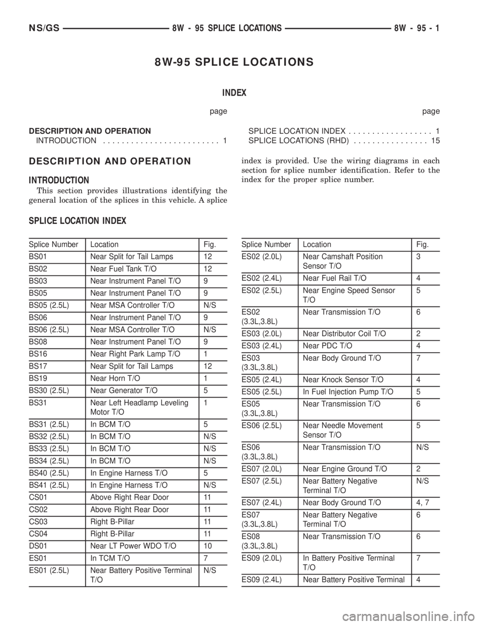
8W-95 SPLICE LOCATIONS
INDEX
page page
DESCRIPTION AND OPERATION
INTRODUCTION......................... 1SPLICE LOCATION INDEX.................. 1
SPLICE LOCATIONS (RHD)................ 15
DESCRIPTION AND OPERATION
INTRODUCTION
This section provides illustrations identifying the
general location of the splices in this vehicle. A spliceindex is provided. Use the wiring diagrams in each
section for splice number identification. Refer to the
index for the proper splice number.
SPLICE LOCATION INDEX
Splice Number Location Fig.
BS01 Near Split for Tail Lamps 12
BS02 Near Fuel Tank T/O 12
BS03 Near Instrument Panel T/O 9
BS05 Near Instrument Panel T/O 9
BS05 (2.5L) Near MSA Controller T/O N/S
BS06 Near Instrument Panel T/O 9
BS06 (2.5L) Near MSA Controller T/O N/S
BS08 Near Instrument Panel T/O 9
BS16 Near Right Park Lamp T/O 1
BS17 Near Split for Tail Lamps 12
BS19 Near Horn T/O 1
BS30 (2.5L) Near Generator T/O 5
BS31 Near Left Headlamp Leveling
Motor T/O1
BS31 (2.5L) In BCM T/O 5
BS32 (2.5L) In BCM T/O N/S
BS33 (2.5L) In BCM T/O N/S
BS34 (2.5L) In BCM T/O N/S
BS40 (2.5L) In Engine Harness T/O 5
BS41 (2.5L) In Engine Harness T/O N/S
CS01 Above Right Rear Door 11
CS02 Above Right Rear Door 11
CS03 Right B-Pillar 11
CS04 Right B-Pillar 11
DS01 Near LT Power WDO T/O 10
ES01 In TCM T/O 7
ES01 (2.5L) Near Battery Positive Terminal
T/ON/SSplice Number Location Fig.
ES02 (2.0L) Near Camshaft Position
Sensor T/O3
ES02 (2.4L) Near Fuel Rail T/O 4
ES02 (2.5L) Near Engine Speed Sensor
T/O5
ES02
(3.3L,3.8L)Near Transmission T/O 6
ES03 (2.0L) Near Distributor Coil T/O 2
ES03 (2.4L) Near PDC T/O 4
ES03
(3.3L,3.8L)Near Body Ground T/O 7
ES05 (2.4L) Near Knock Sensor T/O 4
ES05 (2.5L) In Fuel Injection Pump T/O 5
ES05
(3.3L,3.8L)Near Transmission T/O 6
ES06 (2.5L) Near Needle Movement
Sensor T/O5
ES06
(3.3L,3.8L)Near Transmission T/O N/S
ES07 (2.0L) Near Engine Ground T/O 2
ES07 (2.5L) Near Battery Negative
Terminal T/ON/S
ES07 (2.4L) Near Body Ground T/O 4, 7
ES07
(3.3L,3.8L)Near Battery Negative
Terminal T/O6
ES08
(3.3L,3.8L)Near Transmission T/O 6
ES09 (2.0L) In Battery Positive Terminal
T/O7
ES09 (2.4L) Near Battery Positive Terminal 4
NS/GS8W - 95 SPLICE LOCATIONS 8W - 95 - 1
Page 1034 of 1938
Fig. 8 Instrument Panel SplicesÐLHD
8W - 95 - 10 8W - 95 SPLICE LOCATIONSNS/GS
DESCRIPTION AND OPERATION (Continued)
Page 1046 of 1938
Fig. 7 Instrument Panel SplicesÐRHD
8W - 95 - 22 8W - 95 SPLICE LOCATIONSNS/GS
DESCRIPTION AND OPERATION (Continued)
Page 1186 of 1938

scratches are present, replace the camshaft and
check the cylinder head for damage. Replace the
cylinder head if worn or damaged. Check the lobes
for pitting and wear. If the lobes show signs of
wear, check the corresponding rocker arm roller for
wear or damage. Replace rocker arm/hydraulic lash
adjuster if worn or damaged. If lobes show signs of
pitting on the nose, flank or base circle; replace the
camshaft.
INSTALLATION
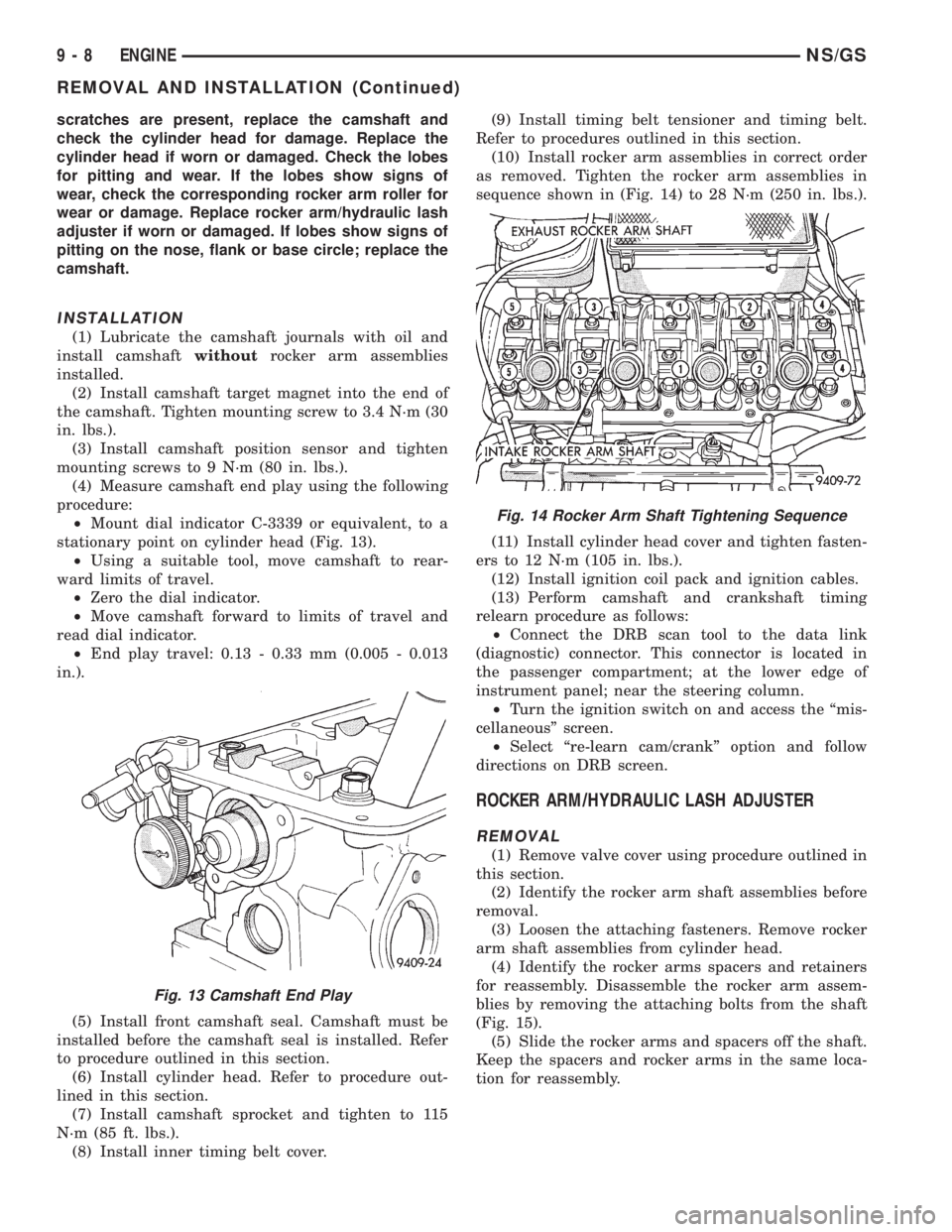
(1) Lubricate the camshaft journals with oil and
install camshaftwithoutrocker arm assemblies
installed.
(2) Install camshaft target magnet into the end of
the camshaft. Tighten mounting screw to 3.4 N´m (30
in. lbs.).
(3) Install camshaft position sensor and tighten
mounting screws to 9 N´m (80 in. lbs.).
(4) Measure camshaft end play using the following
procedure:
²Mount dial indicator C-3339 or equivalent, to a
stationary point on cylinder head (Fig. 13).
²Using a suitable tool, move camshaft to rear-
ward limits of travel.
²Zero the dial indicator.
²Move camshaft forward to limits of travel and
read dial indicator.
²End play travel: 0.13 - 0.33 mm (0.005 - 0.013
in.).
(5) Install front camshaft seal. Camshaft must be
installed before the camshaft seal is installed. Refer
to procedure outlined in this section.
(6) Install cylinder head. Refer to procedure out-
lined in this section.
(7) Install camshaft sprocket and tighten to 115
N´m (85 ft. lbs.).
(8) Install inner timing belt cover.(9) Install timing belt tensioner and timing belt.
Refer to procedures outlined in this section.
(10) Install rocker arm assemblies in correct order
as removed. Tighten the rocker arm assemblies in
sequence shown in (Fig. 14) to 28 N´m (250 in. lbs.).
(11) Install cylinder head cover and tighten fasten-
ers to 12 N´m (105 in. lbs.).
(12) Install ignition coil pack and ignition cables.
(13) Perform camshaft and crankshaft timing
relearn procedure as follows:
²Connect the DRB scan tool to the data link
(diagnostic) connector. This connector is located in
the passenger compartment; at the lower edge of
instrument panel; near the steering column.
²Turn the ignition switch on and access the ªmis-
cellaneousº screen.
²Select ªre-learn cam/crankº option and follow
directions on DRB screen.
ROCKER ARM/HYDRAULIC LASH ADJUSTER
REMOVAL
(1) Remove valve cover using procedure outlined in
this section.
(2) Identify the rocker arm shaft assemblies before
removal.
(3) Loosen the attaching fasteners. Remove rocker
arm shaft assemblies from cylinder head.
(4) Identify the rocker arms spacers and retainers
for reassembly. Disassemble the rocker arm assem-
blies by removing the attaching bolts from the shaft
(Fig. 15).
(5) Slide the rocker arms and spacers off the shaft.
Keep the spacers and rocker arms in the same loca-
tion for reassembly.
Fig. 13 Camshaft End Play
Fig. 14 Rocker Arm Shaft Tightening Sequence
9 - 8 ENGINENS/GS
REMOVAL AND INSTALLATION (Continued)