1996 CHRYSLER VOYAGER instrument panel
[x] Cancel search: instrument panelPage 1411 of 1938
FUEL INJECTION SYSTEMÐ2.5L DIESEL ENGINE
INDEX
page page
GENERAL INFORMATION
INTRODUCTION....................... 43
DESCRIPTION AND OPERATION
AIR CONDITIONING (A/C) CONTROLSÐ
PCM INPUTS........................ 47
AIR CONDITIONING RELAYÐPCM OUTPUT . . 48
BATTERY VOLTAGEÐPCM INPUT.......... 45
BOOST PRESSURE SENSOR............. 45
BRAKE SWITCHÐPCM INPUT............. 47
DATA LINK CONNECTORÐ
PCM INPUT AND OUTPUT.............. 47
DIESEL PCM RELAYÐPCM INPUT......... 48
ENGINE COOLANT GAUGEÐPCM OUTPUT . . 48
ENGINE COOLANT TEMPERATURE SENSORÐ
PCM INPUT......................... 46
ENGINE OIL PRESSURE GAUGEÐ
PCM OUTPUT........................ 48
ENGINE SPEED SENSORÐPCM INPUT..... 46
EXHAUST GAS RECIRCULATION (EGR)
SOLENOIDÐPCM OUTPUT............. 50
FIVE VOLT POWERÐPCM OUTPUT........ 48
FUEL INJECTOR SENSORÐGROUND...... 46
FUEL TIMING SOLENOIDÐPCM OUTPUT.... 48
GLOW PLUG LAMPÐPCM OUTPUT........ 48
GLOW PLUG RELAYÐPCM OUTPUT....... 49
GLOW PLUGS......................... 49
IGNITION CIRCUIT SENSEÐPCM INPUT.... 45
NEEDLE MOVEMENT OR INSTRUMENTED
FIRST INJECTORÐPCM INPUT.......... 45
POWER GROUND...................... 45
POWERTRAIN CONTROL MODULE (PCM) . . . 44
SENSOR RETURNÐPCM INPUT (ANALOG
GROUND)........................... 45SIGNAL GROUNDÐPCM INPUT........... 45
SPEED CONTROLÐPCM INPUTS.......... 48
SPEED CONTROLÐPCM OUTPUTS........ 48
START SIGNALÐPCM INPUT............. 45
TACHOMETERÐPCM OUTPUT............ 49
VEHICLE SPEED SENSORÐPCM INPUT.... 47
VEHICLE THEFT ALARM................. 45
DIAGNOSIS AND TESTING
BOOST PRESSURE SENSOR............. 53
DIAGNOSTIC TROUBLE CODES........... 53
DIESEL DIAGNOSTICS.................. 50
DIESEL PCM RELAY TEST............... 50
ENGINE COOLANT TEMPERATURE
SENSOR TEST....................... 50
ENGINE SPEED SENSOR TEST........... 50
GLOW PLUG RELAY TEST............... 51
GLOW PLUG TEST..................... 51
RELAYSÐOPERATION/TESTING........... 52
VEHICLE SPEED SENSOR TEST........... 53
REMOVAL AND INSTALLATION
A/C CLUTCH RELAY.................... 53
DIESEL PCM RELAY.................... 53
ENGINE COOLANT TEMPERATURE
SENSOR............................ 54
ENGINE SPEED SENSOR................ 53
GLOW PLUG RELAY.................... 55
GLOW PLUGS......................... 54
POWERTRAIN CONTROL MODULE (PCM) . . . 55
VEHICLE SPEED SENSOR............... 55
SPECIFICATIONS
GLOW PLUG CURRENT DRAW............ 56
TORQUE CHARTÐ2.5L DIESEL............ 57
GENERAL INFORMATION
INTRODUCTION
This section will cover components either regulated
or controlled by the Powertrain Control Module
(PCM). The fuel heater relay, fuel heater and fuel
gauge are not operated by the PCM. These compo-
nents are controlled by the ignition (key) switch. All
other fuel system electrical components necessary to
operate the engine are controlled or regulated by the
PCM. Refer to the following PCM description for
more information.
Certain fuel system component failures may cause
a no start, or prevent the engine from running. It is
important to know that the PCM has a featurewhere, if possible, it will ignore the failed sensor, set
a code related to the sensor, and operate the engine
in a ªLimp Homeº mode. When the PCM is operating
in a ªLimp Homeº mode, the Diesel Glow Plug lamp
on the instrument panel will be constantly illumi-
nated, and the engine will most likely have a notice-
able loss of performance. An example of this would be
an Accelerator Pedal Position Sensor failure, and in
that situation, the engine would run at a constant
1100 RPM, regardless of the actual position of the
pedal. This is the most extreme of the three ªLimp
Homeº modes.
In addition to indicating that the glow plugs are
hot enough to start combustion, the Glow Plug Lamp
is also used in the diagnosis of the PCM, and when
NS/GSFUEL SYSTEMÐ2.5L DIESEL ENGINE/2.0L GAS ENGINE 14 - 43
Page 1414 of 1938
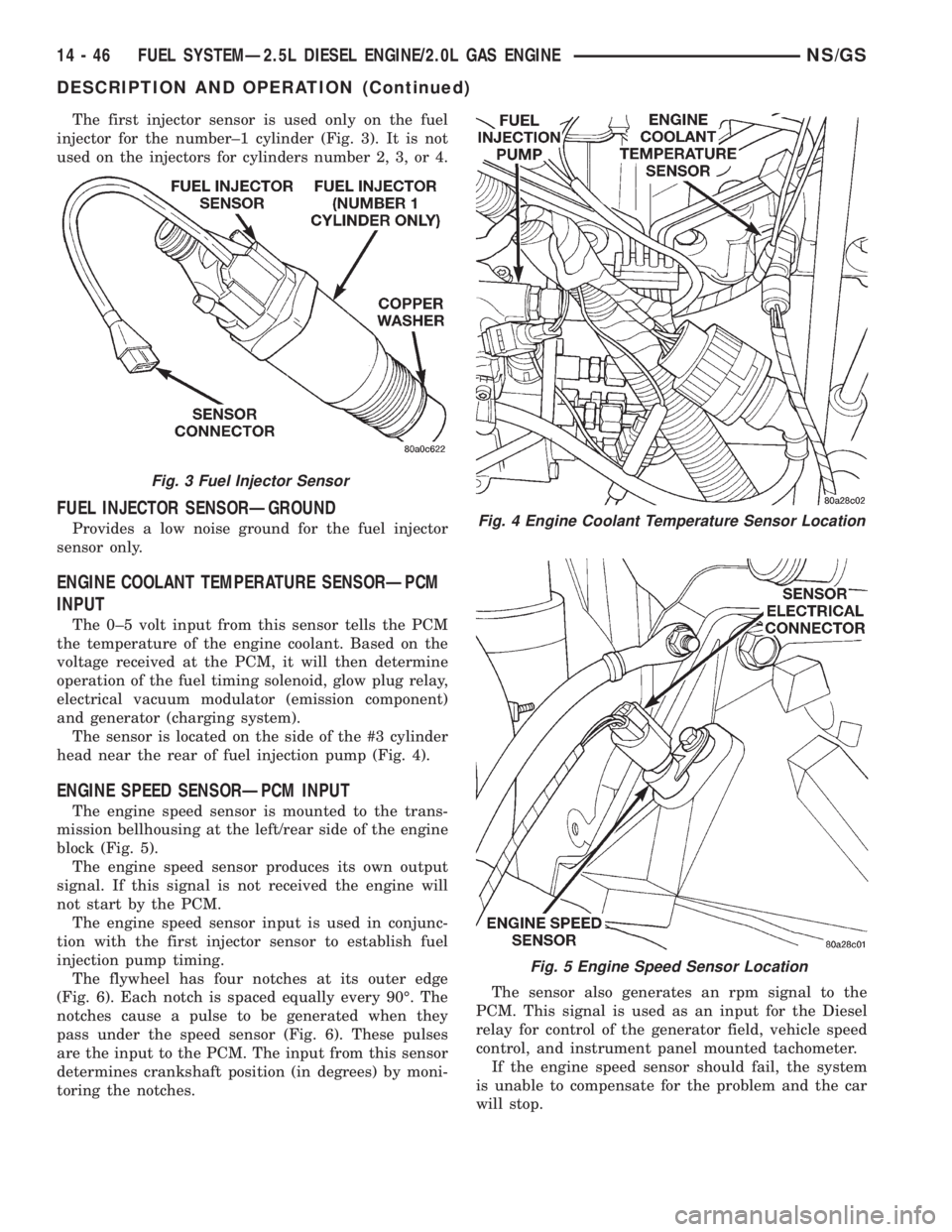
The first injector sensor is used only on the fuel
injector for the number±1 cylinder (Fig. 3). It is not
used on the injectors for cylinders number 2, 3, or 4.
FUEL INJECTOR SENSORÐGROUND
Provides a low noise ground for the fuel injector
sensor only.
ENGINE COOLANT TEMPERATURE SENSORÐPCM
INPUT
The 0±5 volt input from this sensor tells the PCM
the temperature of the engine coolant. Based on the
voltage received at the PCM, it will then determine
operation of the fuel timing solenoid, glow plug relay,
electrical vacuum modulator (emission component)
and generator (charging system).
The sensor is located on the side of the #3 cylinder
head near the rear of fuel injection pump (Fig. 4).
ENGINE SPEED SENSORÐPCM INPUT
The engine speed sensor is mounted to the trans-
mission bellhousing at the left/rear side of the engine
block (Fig. 5).
The engine speed sensor produces its own output
signal. If this signal is not received the engine will
not start by the PCM.
The engine speed sensor input is used in conjunc-
tion with the first injector sensor to establish fuel
injection pump timing.
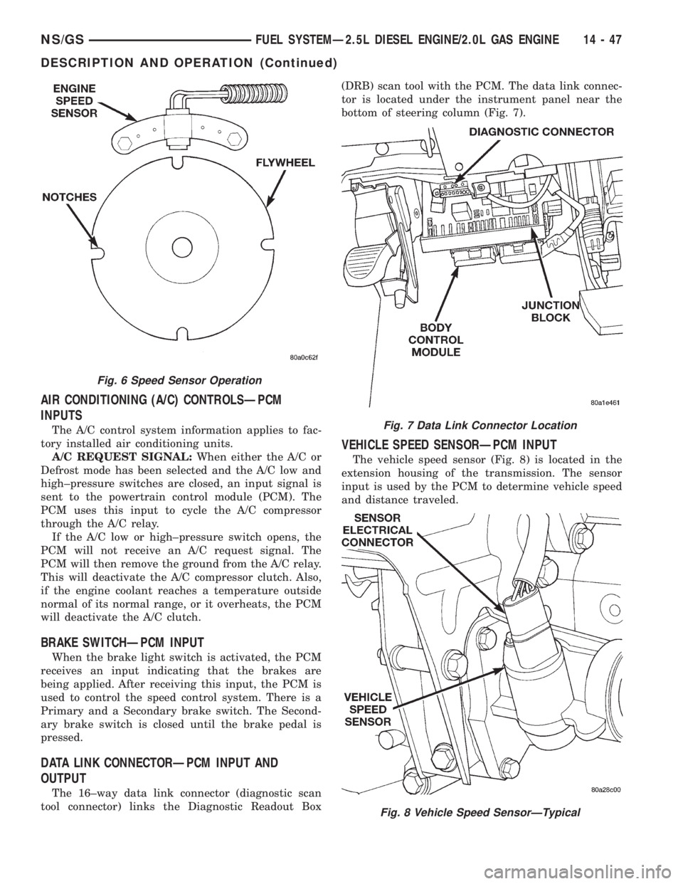
The flywheel has four notches at its outer edge
(Fig. 6). Each notch is spaced equally every 90É. The
notches cause a pulse to be generated when they
pass under the speed sensor (Fig. 6). These pulses
are the input to the PCM. The input from this sensor
determines crankshaft position (in degrees) by moni-
toring the notches.The sensor also generates an rpm signal to the
PCM. This signal is used as an input for the Diesel
relay for control of the generator field, vehicle speed
control, and instrument panel mounted tachometer.
If the engine speed sensor should fail, the system
is unable to compensate for the problem and the car
will stop.
Fig. 3 Fuel Injector Sensor
Fig. 4 Engine Coolant Temperature Sensor Location
Fig. 5 Engine Speed Sensor Location
14 - 46 FUEL SYSTEMÐ2.5L DIESEL ENGINE/2.0L GAS ENGINENS/GS
DESCRIPTION AND OPERATION (Continued)
Page 1415 of 1938
AIR CONDITIONING (A/C) CONTROLSÐPCM
INPUTS
The A/C control system information applies to fac-
tory installed air conditioning units.
A/C REQUEST SIGNAL:When either the A/C or
Defrost mode has been selected and the A/C low and
high±pressure switches are closed, an input signal is
sent to the powertrain control module (PCM). The
PCM uses this input to cycle the A/C compressor
through the A/C relay.
If the A/C low or high±pressure switch opens, the
PCM will not receive an A/C request signal. The
PCM will then remove the ground from the A/C relay.
This will deactivate the A/C compressor clutch. Also,
if the engine coolant reaches a temperature outside
normal of its normal range, or it overheats, the PCM
will deactivate the A/C clutch.
BRAKE SWITCHÐPCM INPUT
When the brake light switch is activated, the PCM
receives an input indicating that the brakes are
being applied. After receiving this input, the PCM is
used to control the speed control system. There is a
Primary and a Secondary brake switch. The Second-
ary brake switch is closed until the brake pedal is
pressed.
DATA LINK CONNECTORÐPCM INPUT AND
OUTPUT
The 16±way data link connector (diagnostic scan
tool connector) links the Diagnostic Readout Box(DRB) scan tool with the PCM. The data link connec-
tor is located under the instrument panel near the
bottom of steering column (Fig. 7).
VEHICLE SPEED SENSORÐPCM INPUT
The vehicle speed sensor (Fig. 8) is located in the
extension housing of the transmission. The sensor
input is used by the PCM to determine vehicle speed
and distance traveled.
Fig. 6 Speed Sensor Operation
Fig. 7 Data Link Connector Location
Fig. 8 Vehicle Speed SensorÐTypical
NS/GSFUEL SYSTEMÐ2.5L DIESEL ENGINE/2.0L GAS ENGINE 14 - 47
DESCRIPTION AND OPERATION (Continued)
Page 1416 of 1938
The speed sensor generates 8 pulses per sensor
revolution. These signals, in conjunction with a
closed throttle signal from the throttle position sen-
sor, indicate a closed throttle deceleration to the
PCM. When the vehicle is stopped at idle, a closed
throttle signal is received by the PCM (but a speed
sensor signal is not received).
In addition to determining distance and vehicle
speed, the output from the sensor is used to control
speed control operation.
SPEED CONTROLÐPCM INPUTS
The speed control system provides five separate
inputs to the PCM; On/Off, Set, Resume/Accel, Cancel,
and Decel.. The On/Off input informs the PCM that
the speed control system has been activated. The Set
input informs the PCM that a fixed vehicle speed has
been selected. The Resume input indicates to the PCM
that the previous fixed speed is requested.
Speed control operation will start at 50 km/h±142
km/h (35±85 mph). The upper range of operation is
not restricted by vehicle speed. Inputs that affect
speed control operation are vehicle speed sensor and
throttle position sensor.
Refer to Group 8H for further speed control infor-
mation.
DIESEL PCM RELAYÐPCM INPUT
A 12 volt signal at this input indicates to the PCM
that the Diesel relay has been activated. The Diesel
relay is located in the PDC. The PDC is located next
to the battery in the engine compartment. For the
location of the relay within the PDC, refer to label on
PDC cover.
This input is used only to sense that the Diesel
relay is energized. If the PCM does not see 12 volts +
at this input when the Diesel relay should be acti-
vated, it will set a Diagnostic Trouble Code (DTC).
FIVE VOLT POWERÐPCM OUTPUT
This circuit supplies approximately 5 volts to
power the Accelerator Pedal Postion Sensor, Mass Air
Flow Sensor, and A/C Pressure Sensor.
ENGINE COOLANT GAUGEÐPCM OUTPUT
Refer to the Instrument Panel and Gauges group
for additional information.
ENGINE OIL PRESSURE GAUGEÐPCM OUTPUT
Refer to the Instrument Panel and Gauges group
for additional information.
GLOW PLUG LAMPÐPCM OUTPUT
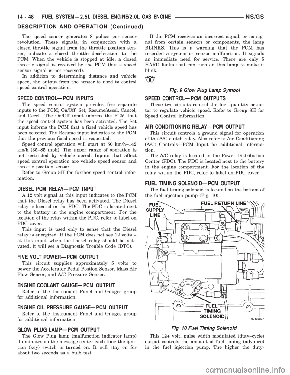
The Glow Plug lamp (malfunction indicator lamp)
illuminates on the message center each time the igni-
tion (key) switch is turned on. It will stay on for
about two seconds as a bulb test.If the PCM receives an incorrect signal, or no sig-
nal from certain sensors or components, the lamp
BLINKS. This is a warning that the PCM has
recorded a system or sensor malfunction. It signals
an immediate need for service. There are only 5
HARD faults that can turn on this lamp to make it
blink.
SPEED CONTROLÐPCM OUTPUTS
These two circuits control the fuel quantity actua-
tor to regulate vehicle speed. Refer to Group 8H for
Speed Control information.
AIR CONDITIONING RELAYÐPCM OUTPUT
This circuit controls a ground signal for operation
of the A/C clutch relay. Also refer to Air Conditioning
(A/C) ControlsÐPCM Input for additional informa-
tion.
The A/C relay is located in the Power Distribution
Center (PDC). The PDC is located next to the battery
in the engine compartment. For the location of the
relay within the PDC, refer to label on PDC cover.
FUEL TIMING SOLENOIDÐPCM OUTPUT
The fuel timing solenoid is located on the bottom of
the fuel injection pump (Fig. 10).
This 12+ volt, pulse width modulated (duty±cycle)
output controls the amount of fuel timing (advance)
in the fuel injection pump. The higher the duty-
Fig. 9 Glow Plug Lamp Symbol
Fig. 10 Fuel Timing Solenoid
14 - 48 FUEL SYSTEMÐ2.5L DIESEL ENGINE/2.0L GAS ENGINENS/GS
DESCRIPTION AND OPERATION (Continued)
Page 1433 of 1938
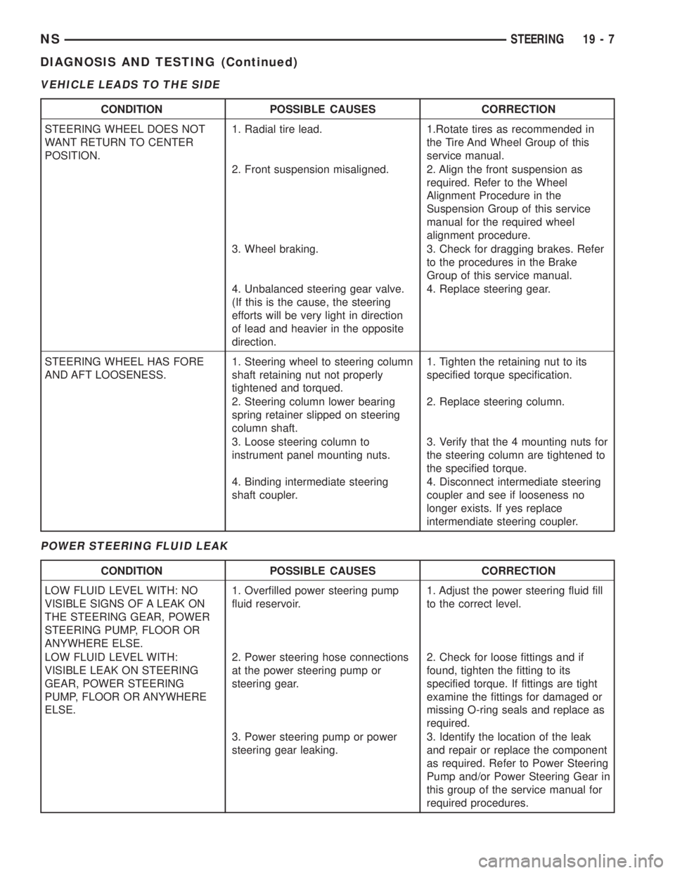
VEHICLE LEADS TO THE SIDE
POWER STEERING FLUID LEAK
CONDITION POSSIBLE CAUSES CORRECTION
STEERING WHEEL DOES NOT
WANT RETURN TO CENTER
POSITION.1. Radial tire lead. 1.Rotate tires as recommended in
the Tire And Wheel Group of this
service manual.
2. Front suspension misaligned. 2. Align the front suspension as
required. Refer to the Wheel
Alignment Procedure in the
Suspension Group of this service
manual for the required wheel
alignment procedure.
3. Wheel braking. 3. Check for dragging brakes. Refer
to the procedures in the Brake
Group of this service manual.
4. Unbalanced steering gear valve.
(If this is the cause, the steering
efforts will be very light in direction
of lead and heavier in the opposite
direction.4. Replace steering gear.
STEERING WHEEL HAS FORE
AND AFT LOOSENESS.1. Steering wheel to steering column
shaft retaining nut not properly
tightened and torqued.1. Tighten the retaining nut to its
specified torque specification.
2. Steering column lower bearing
spring retainer slipped on steering
column shaft.2. Replace steering column.
3. Loose steering column to
instrument panel mounting nuts.3. Verify that the 4 mounting nuts for
the steering column are tightened to
the specified torque.
4. Binding intermediate steering
shaft coupler.4. Disconnect intermediate steering
coupler and see if looseness no
longer exists. If yes replace
intermendiate steering coupler.
CONDITION POSSIBLE CAUSES CORRECTION
LOW FLUID LEVEL WITH: NO
VISIBLE SIGNS OF A LEAK ON
THE STEERING GEAR, POWER
STEERING PUMP, FLOOR OR
ANYWHERE ELSE.1. Overfilled power steering pump
fluid reservoir.1. Adjust the power steering fluid fill
to the correct level.
LOW FLUID LEVEL WITH:
VISIBLE LEAK ON STEERING
GEAR, POWER STEERING
PUMP, FLOOR OR ANYWHERE
ELSE.2. Power steering hose connections
at the power steering pump or
steering gear.2. Check for loose fittings and if
found, tighten the fitting to its
specified torque. If fittings are tight
examine the fittings for damaged or
missing O-ring seals and replace as
required.
3. Power steering pump or power
steering gear leaking.3. Identify the location of the leak
and repair or replace the component
as required. Refer to Power Steering
Pump and/or Power Steering Gear in
this group of the service manual for
required procedures.
NSSTEERING 19 - 7
DIAGNOSIS AND TESTING (Continued)
Page 1464 of 1938
DIAGNOSIS AND TESTING
STEERING COLUMN
For diagnosis of conditions relating to the steering
column, refer to the steering system diagnosis charts,
in the diagnosis and testing section at the beginning
of this group.
SERVICE PROCEDURES
STEERING COLUMN SERVICE PROCEDURE
WARNINGS
WARNING: BEFORE BEGINNING ANY SERVICE
PROCEDURES THAT INVOLVES REMOVING THE
AIR BAG. REMOVE AND ISOLATE THE NEGATIVE
(-) BATTERY CABLE (GROUND) FROM THE VEHI-
CLE BATTERY. THIS IS THE ONLY SURE WAY TO
DISABLE THE AIR BAG SYSTEM. FAILURE TO DO
THIS COULD RESULT IN ACCIDENTAL AIR BAG
DEPLOYMENT AND POSSIBLE PERSONAL INJURY.
WARNING: THE AIR BAG SYSTEM IS A SENSITIVE,
COMPLEX ELECTRO-MECHANICAL UNIT. BEFORE
ATTEMPTING TO DIAGNOSE, REMOVE OR INSTALL
THE AIR BAG SYSTEM COMPONENTS YOU MUST
FIRST DISCONNECT AND ISOLATE THE BATTERY
NEGATIVE (GROUND) CABLE. FAILURE TO DO SO
COULD RESULT IN ACCIDENTAL DEPLOYMENT OF
THE AIR BAG AND POSSIBLE PERSONAL INJURY.
THE FASTENERS, SCREWS, AND BOLTS, ORIGI-
NALLY USED FOR THE AIR BAG COMPONENTS,
HAVE SPECIAL COATINGS AND ARE SPECIFI-
CALLY DESIGNED FOR THE AIR BAG SYSTEM.
THEY MUST NEVER BE REPLACED WITH ANY SUB-
STITUTES. ANYTIME A NEW FASTENER IS
NEEDED, REPLACE WITH THE CORRECT FASTEN-
ERS PROVIDED IN THE SERVICE PACKAGE OR
FASTENERS LISTED IN THE PARTS BOOKS.
BEFORE SERVICING A STEERING COLUMN
EQUIPPED WITH AN AIR BAG, REFER TO GROUP
8M, ELECTRICAL FOR PROPER AND SAFE SER-
VICE PROCEDURES.
NOTE: Safety goggles should be worn at all times
when working on steering columns.
CAUTION: Disconnect negative (ground) cable
from the battery, before servicing any column com-
ponent.CAUTION: Do not attempt to remove the pivot pins
to disassemble the tilting mechanism. Damage will
occur.
REMOVAL AND INSTALLATION
STEERING COLUMN ASSEMBLY
To service the steering wheel and its components
or the air bag, refer to Group 8M, Restraint Systems.
Follow all WARNINGS.
To service the switches, refer to the appropriate
section of Group 8, Electrical.
To replace the steering column assembly, refer to
the steering column removal procedure.
REMOVE
(1) Make sure the front wheels of the vehicle are
in thestraight aheadposition before beginning the
column removal procedure.
(2) Disconnect negative (ground) cable from the
battery and isolate cable from battery terminal.
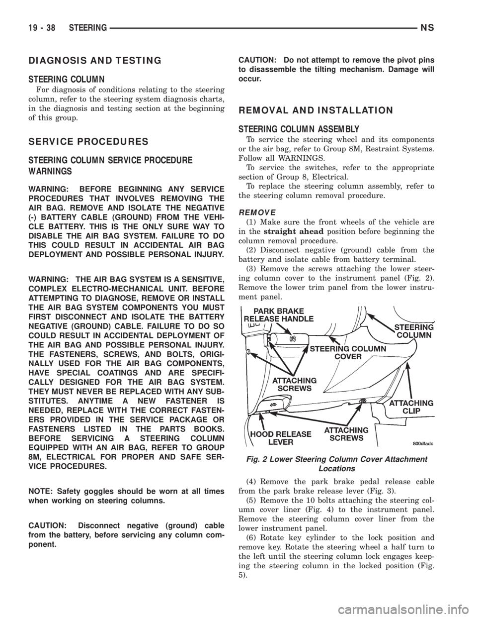
(3) Remove the screws attaching the lower steer-
ing column cover to the instrument panel (Fig. 2).
Remove the lower trim panel from the lower instru-
ment panel.
(4) Remove the park brake pedal release cable
from the park brake release lever (Fig. 3).
(5) Remove the 10 bolts attaching the steering col-
umn cover liner (Fig. 4) to the instrument panel.
Remove the steering column cover liner from the
lower instrument panel.
(6) Rotate key cylinder to the lock position and
remove key. Rotate the steering wheel a half turn to
the left until the steering column lock engages keep-
ing the steering column in the locked position (Fig.
5).
Fig. 2 Lower Steering Column Cover Attachment
Locations
19 - 38 STEERINGNS
Page 1467 of 1938
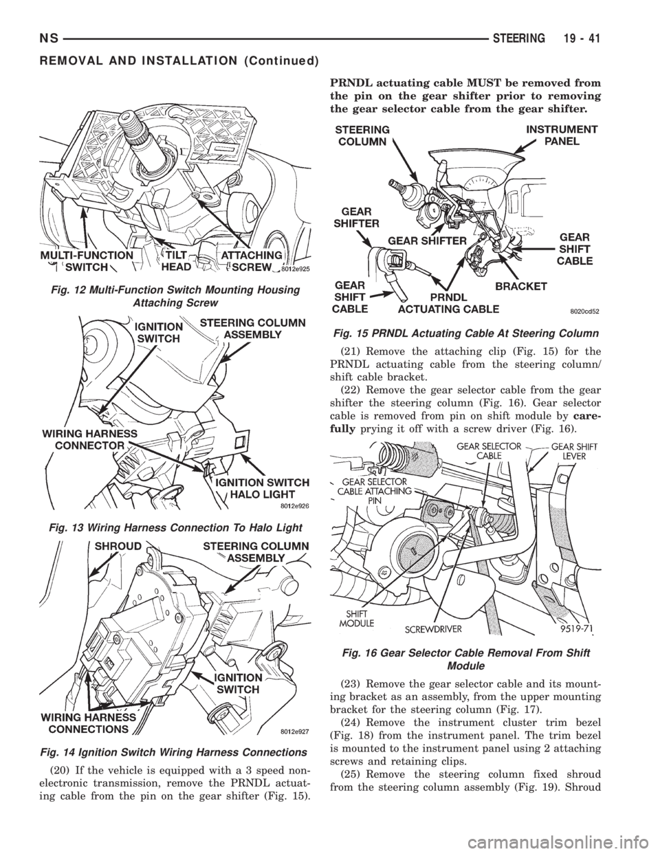
(20) If the vehicle is equipped with a 3 speed non-
electronic transmission, remove the PRNDL actuat-
ing cable from the pin on the gear shifter (Fig. 15).PRNDL actuating cable MUST be removed from
the pin on the gear shifter prior to removing
the gear selector cable from the gear shifter.
(21) Remove the attaching clip (Fig. 15) for the
PRNDL actuating cable from the steering column/
shift cable bracket.
(22) Remove the gear selector cable from the gear
shifter the steering column (Fig. 16). Gear selector
cable is removed from pin on shift module bycare-
fullyprying it off with a screw driver (Fig. 16).
(23) Remove the gear selector cable and its mount-
ing bracket as an assembly, from the upper mounting
bracket for the steering column (Fig. 17).
(24) Remove the instrument cluster trim bezel
(Fig. 18) from the instrument panel. The trim bezel
is mounted to the instrument panel using 2 attaching
screws and retaining clips.
(25) Remove the steering column fixed shroud
from the steering column assembly (Fig. 19). Shroud
Fig. 12 Multi-Function Switch Mounting Housing
Attaching Screw
Fig. 13 Wiring Harness Connection To Halo Light
Fig. 14 Ignition Switch Wiring Harness Connections
Fig. 15 PRNDL Actuating Cable At Steering Column
Fig. 16 Gear Selector Cable Removal From Shift
Module
NSSTEERING 19 - 41
REMOVAL AND INSTALLATION (Continued)
Page 1469 of 1938
(28) Remove steering column assembly from vehi-
cle. Use care to avoid damage to paint or interior
trim.
INSTALL
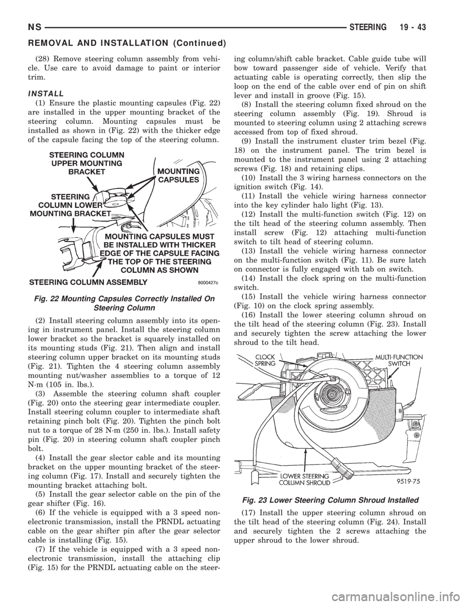
(1) Ensure the plastic mounting capsules (Fig. 22)
are installed in the upper mounting bracket of the
steering column. Mounting capsules must be
installed as shown in (Fig. 22) with the thicker edge
of the capsule facing the top of the steering column.
(2) Install steering column assembly into its open-
ing in instrument panel. Install the steering column
lower bracket so the bracket is squarely installed on
its mounting studs (Fig. 21). Then align and install
steering column upper bracket on its mounting studs
(Fig. 21). Tighten the 4 steering column assembly
mounting nut/washer assemblies to a torque of 12
N´m (105 in. lbs.).
(3) Assemble the steering column shaft coupler
(Fig. 20) onto the steering gear intermediate coupler.
Install steering column coupler to intermediate shaft
retaining pinch bolt (Fig. 20). Tighten the pinch bolt
nut to a torque of 28 N´m (250 in. lbs.). Install safety
pin (Fig. 20) in steering column shaft coupler pinch
bolt.
(4) Install the gear slector cable and its mounting
bracket on the upper mounting bracket of the steer-
ing column (Fig. 17). Install and securely tighten the
mounting bracket attaching bolt.
(5) Install the gear selector cable on the pin of the
gear shifter (Fig. 16).
(6) If the vehicle is equipped with a 3 speed non-
electronic transmission, install the PRNDL actuating
cable on the gear shifter pin after the gear selector
cable is installing (Fig. 15).
(7) If the vehicle is equipped with a 3 speed non-
electronic transmission, install the attaching clip
(Fig. 15) for the PRNDL actuating cable on the steer-ing column/shift cable bracket. Cable guide tube will
bow toward passenger side of vehicle. Verify that
actuating cable is operating correctly, then slip the
loop on the end of the cable over end of pin on shift
lever and install in groove (Fig. 15).
(8) Install the steering column fixed shroud on the
steering column assembly (Fig. 19). Shroud is
mounted to steering column using 2 attaching screws
accessed from top of fixed shroud.
(9) Install the instrument cluster trim bezel (Fig.
18) on the instrument panel. The trim bezel is
mounted to the instrument panel using 2 attaching
screws (Fig. 18) and retaining clips.
(10) Install the 3 wiring harness connectors on the
ignition switch (Fig. 14).
(11) Install the vehicle wiring harness connector
into the key cylinder halo light (Fig. 13).
(12) Install the multi-function switch (Fig. 12) on
the tilt head of the steering column assembly. Then
install screw (Fig. 12) attaching multi-function
switch to tilt head of steering column.
(13) Install the vehicle wiring harness connector
on the multi-function switch (Fig. 11). Be sure latch
on connector is fully engaged with tab on switch.
(14) Install the clock spring on the multi-function
switch.
(15) Install the vehicle wiring harness connector
(Fig. 10) on the clock spring assembly.
(16) Install the lower steering column shroud on
the tilt head of the steering column (Fig. 23). Install
and securely tighten the screw attaching the lower
shroud to the tilt head.
(17) Install the upper steering column shroud on
the tilt head of the steering column (Fig. 24). Install
and securely tighten the 2 screws attaching the
upper shroud to the lower shroud.
Fig. 22 Mounting Capsules Correctly Installed On
Steering Column
Fig. 23 Lower Steering Column Shroud Installed
NSSTEERING 19 - 43
REMOVAL AND INSTALLATION (Continued)