1996 CHRYSLER VOYAGER ABS
[x] Cancel search: ABSPage 1361 of 1938
POWERTRAIN CONTROL MODULE
REMOVAL
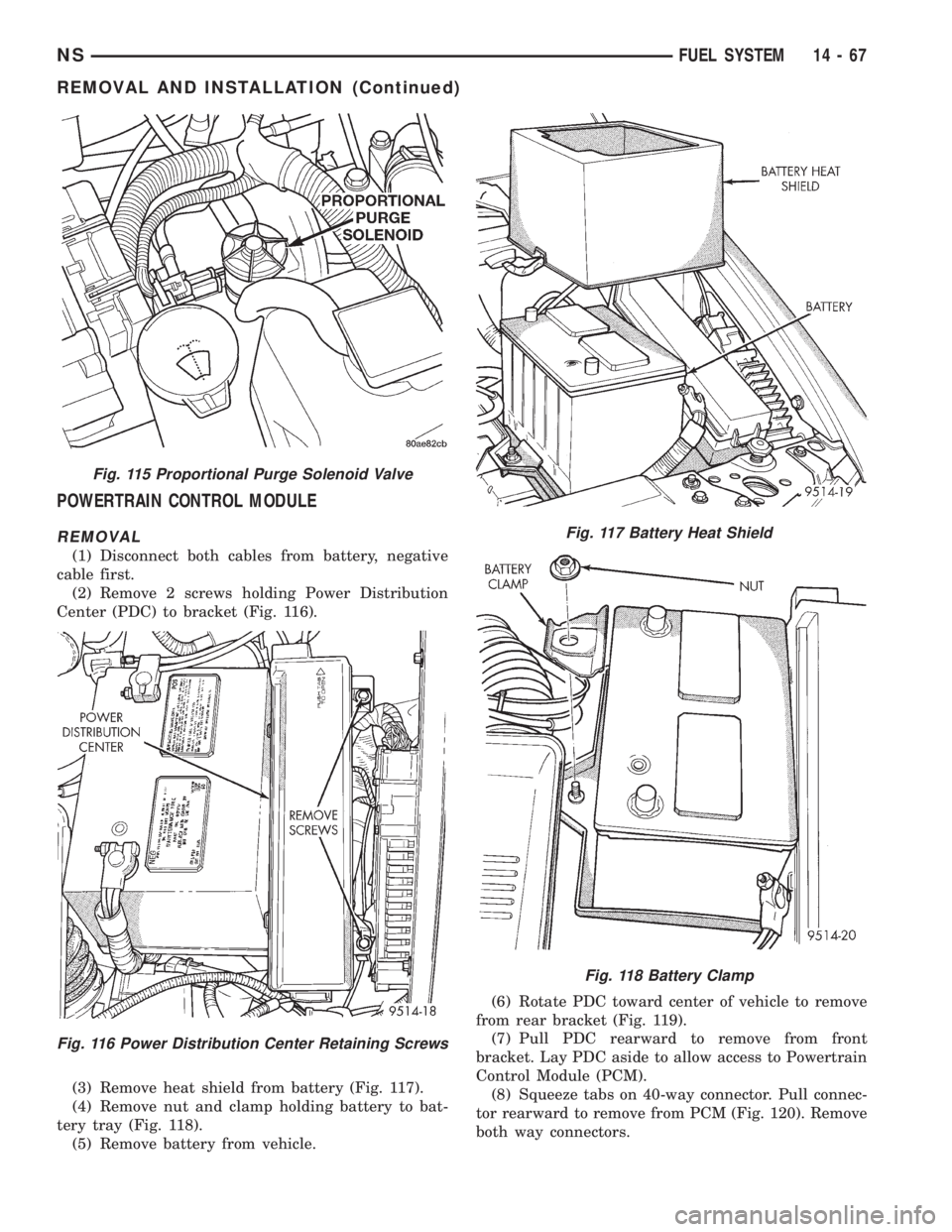
(1) Disconnect both cables from battery, negative
cable first.
(2) Remove 2 screws holding Power Distribution
Center (PDC) to bracket (Fig. 116).
(3) Remove heat shield from battery (Fig. 117).
(4) Remove nut and clamp holding battery to bat-
tery tray (Fig. 118).
(5) Remove battery from vehicle.(6) Rotate PDC toward center of vehicle to remove
from rear bracket (Fig. 119).
(7) Pull PDC rearward to remove from front
bracket. Lay PDC aside to allow access to Powertrain
Control Module (PCM).
(8) Squeeze tabs on 40-way connector. Pull connec-
tor rearward to remove from PCM (Fig. 120). Remove
both way connectors.
Fig. 115 Proportional Purge Solenoid Valve
Fig. 116 Power Distribution Center Retaining Screws
Fig. 117 Battery Heat Shield
Fig. 118 Battery Clamp
NSFUEL SYSTEM 14 - 67
REMOVAL AND INSTALLATION (Continued)
Page 1375 of 1938
leaks are not present. The component should be
replaced immediately if there is any evidence of deg-
radation that could result in failure.
Never attempt to repair a plastic fuel line/tube or a
quick±connect fitting. Replace complete line/tube as
necessary.
Avoid contact of any fuel tubes/hoses with other
vehicle components that could cause abrasions or
scuffing. Be sure that the fuel lines/tubes are prop-
erly routed to prevent pinching and to avoid heat
sources.
The lines/tubes/hoses are of a special construction.
If it is necessary to replace these lines/tubes/hoses,
use only original equipment type.
The hose clamps used to secure the rubber hoses
are of a special rolled edge construction. This con-
struction is used to prevent the edge of the clamp
from cutting into the hose. Only these rolled edge
type clamps may be used in this system. All other
types of clamps may cut into the hoses and cause
fuel leaks.
Where a rubber hose is joined to a metal tube
(staked), do not attempt to repair. Replace entire
line/tube assembly.
Use new original equipment type hose clamps.
Tighten hose clamps to 2 N´m (20 in. lbs.) torque.
QUICK-CONNECT FITTINGSÐLOW PRESSURE
TYPE
Different types of quick-connect fittings are used to
attach various fuel system components. These are: a
single-tab type, a two-tab type or a plastic retainer
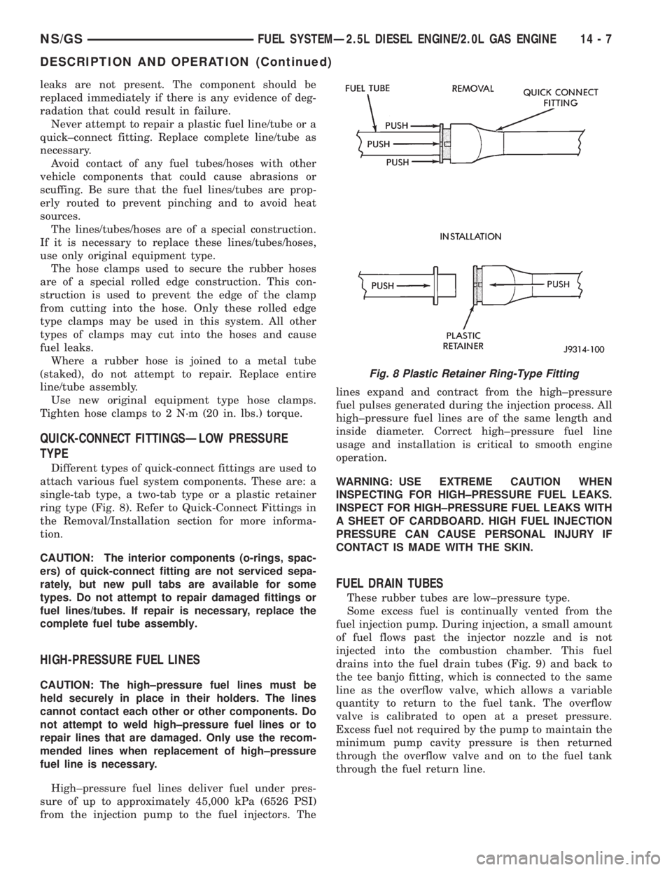
ring type (Fig. 8). Refer to Quick-Connect Fittings in
the Removal/Installation section for more informa-
tion.
CAUTION: The interior components (o-rings, spac-
ers) of quick-connect fitting are not serviced sepa-
rately, but new pull tabs are available for some
types. Do not attempt to repair damaged fittings or
fuel lines/tubes. If repair is necessary, replace the
complete fuel tube assembly.
HIGH-PRESSURE FUEL LINES
CAUTION: The high±pressure fuel lines must be
held securely in place in their holders. The lines
cannot contact each other or other components. Do
not attempt to weld high±pressure fuel lines or to
repair lines that are damaged. Only use the recom-
mended lines when replacement of high±pressure
fuel line is necessary.
High±pressure fuel lines deliver fuel under pres-
sure of up to approximately 45,000 kPa (6526 PSI)
from the injection pump to the fuel injectors. Thelines expand and contract from the high±pressure
fuel pulses generated during the injection process. All
high±pressure fuel lines are of the same length and
inside diameter. Correct high±pressure fuel line
usage and installation is critical to smooth engine
operation.
WARNING: USE EXTREME CAUTION WHEN
INSPECTING FOR HIGH±PRESSURE FUEL LEAKS.
INSPECT FOR HIGH±PRESSURE FUEL LEAKS WITH
A SHEET OF CARDBOARD. HIGH FUEL INJECTION
PRESSURE CAN CAUSE PERSONAL INJURY IF
CONTACT IS MADE WITH THE SKIN.
FUEL DRAIN TUBES
These rubber tubes are low±pressure type.
Some excess fuel is continually vented from the
fuel injection pump. During injection, a small amount
of fuel flows past the injector nozzle and is not
injected into the combustion chamber. This fuel
drains into the fuel drain tubes (Fig. 9) and back to
the tee banjo fitting, which is connected to the same
line as the overflow valve, which allows a variable
quantity to return to the fuel tank. The overflow
valve is calibrated to open at a preset pressure.
Excess fuel not required by the pump to maintain the
minimum pump cavity pressure is then returned
through the overflow valve and on to the fuel tank
through the fuel return line.
Fig. 8 Plastic Retainer Ring-Type Fitting
NS/GSFUEL SYSTEMÐ2.5L DIESEL ENGINE/2.0L GAS ENGINE 14 - 7
DESCRIPTION AND OPERATION (Continued)
Page 1400 of 1938
FUEL INJECTION SYSTEMÐ2.0L ENGINE
INDEX
page page
GENERAL INFORMATION
INTRODUCTIONÐ2.0L ENGINE............ 32
MODES OF OPERATIONÐ2.0L ENGINE..... 32
DESCRIPTION AND OPERATION
AIR CONDITIONING (A/C) RELAYÐPCM
OUTPUTÐ2.0L ENGINE................ 35
AIR CONDITIONING PRESSURE
TRANSDUCERÐPCM INPUTÐ
2.0L ENGINE......................... 33
AIR CONDITIONING SWITCH SENSEÐ
PCM INPUTÐ2.0L ENGINE.............. 33
AUTOMATIC SHUTDOWN (ASD) SENSEÐ
PCM INPUTÐ2.0L ENGINE.............. 33
AUTOMATIC SHUTDOWN RELAYÐ
PCM OUTPUTÐ2.0L ENGINE............ 35
BATTERY VOLTAGEÐPCM INPUTÐ
2.0L ENGINE......................... 33
CAMSHAFT POSITION SENSORÐ
PCM INPUTÐ2.0L ENGINE.............. 33
CRANKSHAFT POSITION SENSORÐ
PCM INPUTÐ2.0L ENGINE.............. 33
DATA LINK CONNECTORÐPCM OUTPUTÐ
2.0L ENGINE......................... 35
ELECTRONIC EGR TRANSDUCERÐ
PCM OUTPUTÐ2.0L ENGINE............ 35
ENGINE COOLANT TEMPERATURE SENSORÐ
PCM INPUTÐ2.0L ENGINE.............. 33
FUEL INJECTORSÐPCM OUTPUTÐ
2.0L ENGINE......................... 35
FUEL PUMP RELAYÐPCM OUTPUTÐ
2.0L ENGINE......................... 35
GENERATOR FIELDÐPCM OUTPUTÐ
2.0L ENGINE......................... 35
HEATED OXYGEN SENSORÐPCM INPUTÐ
2.0L ENGINE......................... 33
IDLE AIR CONTROL MOTORÐPCM OUTPUTÐ
2.0L ENGINE......................... 35
IGNITION COILÐPCM OUTPUTÐ
2.0L ENGINE......................... 36KNOCK SENSORÐPCM INPUTÐ
2.0L ENGINE......................... 34
MALFUNCTION INDICATOR (CHECK ENGINE)
LAMPÐPCM OUTPUTÐ2.0L ENGINE...... 36
MANIFOLD ABSOLUTE PRESSURE
(MAP SENSOR)ÐPCM INPUTÐ
2.0L ENGINE......................... 34
POWERTRAIN CONTROL MODULEÐ
2.0L ENGINE......................... 33
RADIATOR FAN CONTROL MODULEÐ
PCM OUTPUTÐ2.0L ENGINE............ 36
SPEED CONTROL SOLENOIDSÐ
PCM OUTPUTÐ2.0L ENGINE............ 36
SPEED CONTROLÐPCM INPUTÐ
2.0L ENGINE......................... 34
STARTER RELAYÐPCM OUTPUTÐ
2.0L ENGINE......................... 35
SYSTEM DIAGNOSISÐ2.0L ENGINE........ 33
TACHOMETERÐPCM OUTPUTÐ
2.0L ENGINE......................... 36
THROTTLE BODYÐ2.0L ENGINE.......... 36
THROTTLE POSITION SENSOR/ IDLE AIR
CONTROL MOTORÐPCM INPUTÐ
2.0L ENGINE......................... 35
DIAGNOSIS AND TESTING
ASD AND FUEL PUMP RELAYSÐ
2.0L ENGINE......................... 39
CAMSHAFT AND CRANKSHAFT
POSITION SENSOR................... 40
ENGINE COOLANT TEMPERATURE
SENSOR............................ 40
KNOCK SENSORÐ2.0L ENGINE........... 40
MANIFOLD ABSOLUTE PRESSURE
(MAP) SENSORÐ2.0L ENGINE........... 39
THROTTLE BODY MINIMUM AIR FLOW..... 41
THROTTLE POSITION SENSOR........... 40
VISUAL INSPECTIONÐSOHC............. 36
SPECIFICATIONS
TORQUE............................. 42
GENERAL INFORMATION
INTRODUCTIONÐ2.0L ENGINE
Refer to the Introduction for 2.4/3.0/3.3/3.8L
engines under General Information in the Fuel Injec-
tion System section of group 14 for more information.
MODES OF OPERATIONÐ2.0L ENGINE
Refer to the Modes of Operation for 2.4/3.0/3.3/3.8L
engines under General Information in the Fuel Injec-
tion System section of group 14 for more information.
14 - 32 FUEL SYSTEMÐ2.5L DIESEL ENGINE/2.0L GAS ENGINENS/GS
Page 1402 of 1938
KNOCK SENSORÐPCM INPUTÐ2.0L ENGINE
Refer to the Knock Sensor for 2.4/3.0/3.3/3.8L
engines under Description and Operation in the Fuel
Injection System section of group 14 for more infor-
mation.
MANIFOLD ABSOLUTE PRESSURE (MAP
SENSOR)ÐPCM INPUTÐ2.0L ENGINE
Refer to the Manifold Absolute Pressure and
Intake Air Temperature sensors for 2.4/3.0/3.3/3.8L
engines under Description and Operation in the Fuel
Injection System section of group 14 for more infor-
mation.
SPEED CONTROLÐPCM INPUTÐ2.0L ENGINE
Refer to the Speed Control for 2.4/3.0/3.3/3.8L
engines under Description and Operation in the Fuel
Injection System section of group 14 for more infor-
mation.
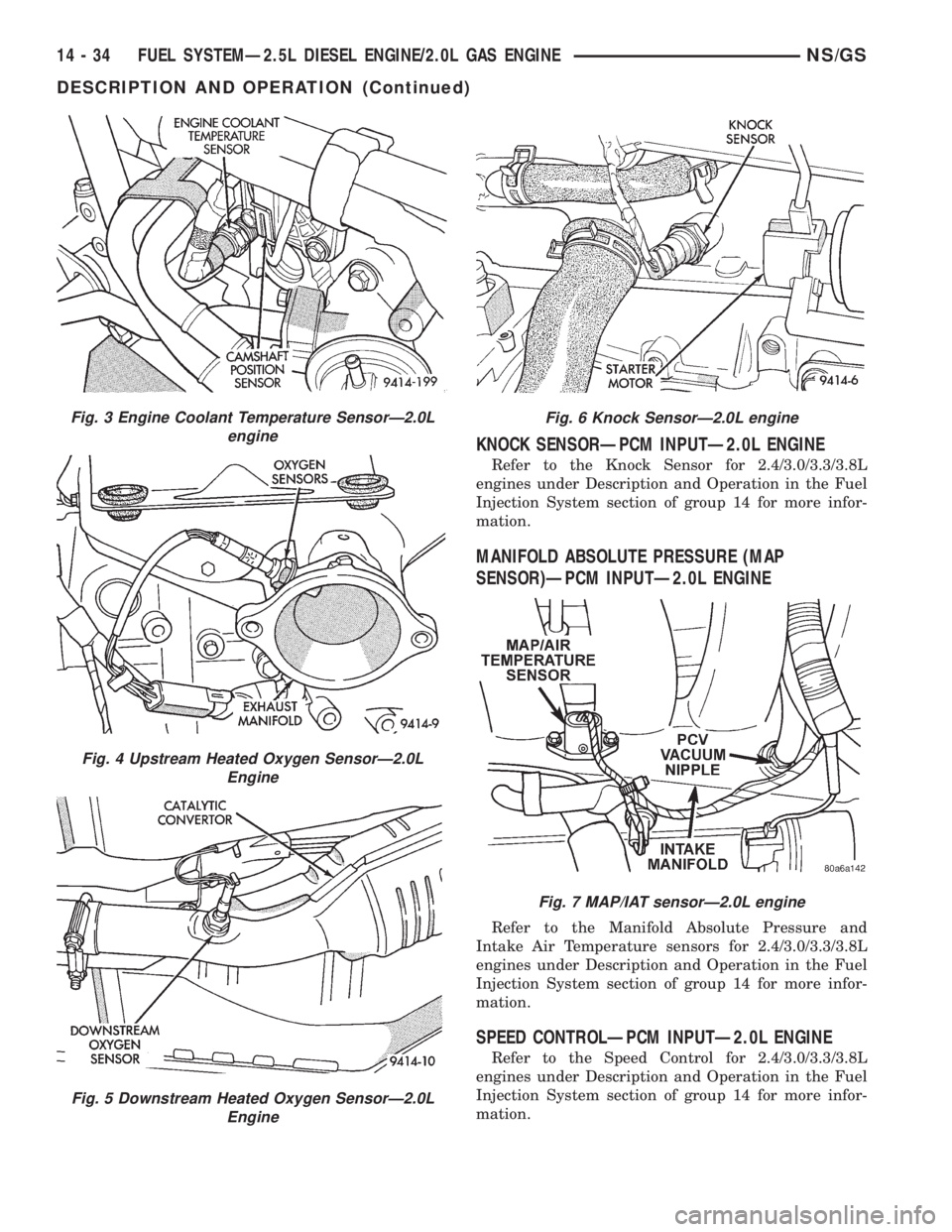
Fig. 3 Engine Coolant Temperature SensorÐ2.0L
engine
Fig. 4 Upstream Heated Oxygen SensorÐ2.0L
Engine
Fig. 5 Downstream Heated Oxygen SensorÐ2.0L
Engine
Fig. 6 Knock SensorÐ2.0L engine
Fig. 7 MAP/IAT sensorÐ2.0L engine
14 - 34 FUEL SYSTEMÐ2.5L DIESEL ENGINE/2.0L GAS ENGINENS/GS
DESCRIPTION AND OPERATION (Continued)
Page 1407 of 1938

(20) Inspect the electrical connections at the
upstream and downstream heated oxygen sensors
(Fig. 25) and (Fig. 26).
(21) Inspect the fuel pump module electrical con-
nection at the fuel tank for corrosion or damage (Fig.27). Check for pinched, kinked or damaged fuel sup-
ply tube.
(22) Inspect the connections to the speed control
servo, if equipped. Refer to Group 8H, Vehicle Speed
Control.
(23) Inspect the connection at the battery temper-
ature sensor.
ASD AND FUEL PUMP RELAYSÐ2.0L ENGINE
Refer to the ASD and Fuel Pump Relays for 2.4/
3.0/3.3/3.8L engines under Diagnosis and Testing in
the Fuel Injection System section of group 14 for
more information.
MANIFOLD ABSOLUTE PRESSURE (MAP)
SENSORÐ2.0L ENGINE
To perform a complete test of the MAP sensor and
its circuitry, refer to the DRB scan tool and appropri-
ate Powertrain Diagnostics Procedures manual. To
test the MAP sensor only, refer to the following:
Fig. 23 Vehicle Speed Sensor
Fig. 24 Power Steering Pressure Switch
Fig. 25 Upstream Heated Oxygen Sensor
Fig. 26 Downstream Heated Oxygen Sensor
Fig. 27 Fuel Pump Module Electrical Connector
NS/GSFUEL SYSTEMÐ2.5L DIESEL ENGINE/2.0L GAS ENGINE 14 - 39
DIAGNOSIS AND TESTING (Continued)
Page 1428 of 1938
DIAGNOSIS AND TESTING
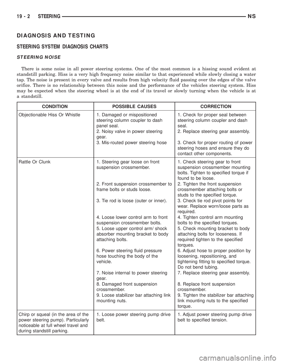
STEERING SYSTEM DIAGNOSIS CHARTS
STEERING NOISE
There is some noise in all power steering systems. One of the most common is a hissing sound evident at
standstill parking. Hiss is a very high frequency noise similar to that experienced while slowly closing a water
tap. The noise is present in every valve and results from high velocity fluid passing over the edges of the valve
orifice. There is no relationship between this noise and the performance of the vehicles steering system. Hiss
may be expected when the steering wheel is at the end of its travel or slowly turning when the vehicle is at
a standstill.
CONDITION POSSIBLE CAUSES CORRECTION
Objectionable Hiss Or Whistle 1. Damaged or mispositioned
steering column coupler to dash
panel seal.1. Check for proper seal between
steering column coupler and dash
seal.
2. Noisy valve in power steering
gear.2. Replace steering gear assembly.
3. Mis-routed power steering hose 3. Check for proper routing of power
steering hoses and ensure they do
contact other components.
Rattle Or Clunk 1. Steering gear loose on front
suspension crossmember.1. Check steering gear to front
suspension crossmember mounting
bolts. Tighten to specified torque if
found to be loose.
2. Front suspension crossmember to
frame bolts or studs loose.2. Tighten the front suspension
crossmember attaching bolts or
studs to the specified torque.
3. Tie rod is loose (outer or inner). 3. Check tie rod pivot points for
wear. Replace worn/loose parts as
required.
4. Loose lower control arm to front
suspension crossmember bolts.4. Tighten control arm mounting
bolts to the specified torques.
5. Loose upper control arm/ shock
absorber mounting bracket to body
attaching bolts.5. Check mounting bracket to body
attaching bolts for looseness. If
required tighten to the specified
torques.
6. Power steering fluid pressure
hose touching the body of the
vehicle.6. Adjust hose to proper position by
loosening, repositioning, and
tightening fitting to specified torque.
Do not bend tubing.
7. Noise internal to power steering
gear.7. Replace steering gear assembly.
8. Damaged front suspension
crossmember.8. Replace front suspension
crossmember.
9. Loose stabilizer bar attaching link
mounting nuts.9. Tighten the stabilizer bar attaching
link mounting nuts to the specified
torque.
Chirp or squeal (in the area of the
power steering pump). Particularly
noticeable at full wheel travel and
during standstill parking.1. Loose power steering pump drive
belt.1. Adjust power steering pump drive
belt to specified tension.
19 - 2 STEERINGNS
Page 1448 of 1938
REMOTE POWER STEERING FLUID RESERVOIR
REMOVE
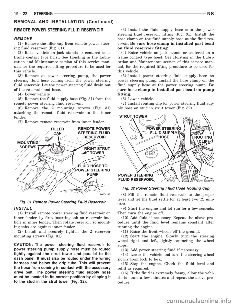
(1) Remove the filler cap from remote power steer-
ing fluid reservoir (Fig. 31).
(2) Raise vehicle on jack stands or centered on a
frame contact type hoist. See Hoisting in the Lubri-
cation and Maintenance section of this service man-
ual, for the required lifting procedure to be used for
this vehicle.
(3) Remove at power steering pump, the power
steering fluid hose coming from the power steering
fluid reservoir. Let the power steering fluid drain out
of the reservoir and hose.
(4) Lower vehicle.
(5) Remove the fluid supply hose (Fig. 31) from the
remote power steering fluid reservoir.
(6) Remove the 2 mounting screws (Fig. 31)
attaching the remote fluid reservoir to the inner
fender.
(7) Remove remote reservoir from inner fender.
INSTALL
(1) Install remote power steering fluid reservoir on
inner fender, by first inserting tab on reservoir into
hole in inner fender. Then rotate reservoir so mount-
ing tabs are against inner fender.
(2) Install and securely tighten the 2 reservoir
mounting screws (Fig. 31).
CAUTION: The power steering fluid reservoir to
power steering pump supply hose must be routed
tightly against the strut tower and parallel to the
dash panel. It must also be routed under the wiring
harness and below the drip tube. This will prevent
the hose from coming in contact with the accessory
drive belt. The power steering fluid supply hose
must be located in its correct position by clipping it
to the stud in the strut tower (Fig. 32).(3) Install the fluid supply hose onto the power
steering fluid reservoir fitting (Fig. 31). Install the
hose clamp on the fluid supply hose at the fluid res-
ervoir.Be sure hose clamp in installed past bead
on fluid reservoir fitting.
(4) Raise vehicle on jack stands or centered on a
frame contact type hoist. See Hoisting in the Lubri-
cation and Maintenance section of this service man-
ual, for the required lifting procedure to be used for
this vehicle.
(5) Install power steering fluid supply hose on
power steering pump. Install the hose clamp on the
fluid supply hose at the power steering pump.Be
sure hose clamp in installed past bead on pump
fitting.
(6) Lower vehicle.
(7) Install routing clip for power steering fluid sup-
ply hose on stud in strut tower (Fig. 32).
(8) Fill the remote fluid reservoir to the proper
level and let the fluid settle for at least two (2) min-
utes.
(9) Start the engine and let run for a few seconds.
Then turn the engine off.
(10) Add fluid if necessary. Repeat the above pro-
cedure until the fluid level remains constant after
running the engine.
(11) Raise the front wheels off the ground.
(12) Start the engine. Slowly turn the steering
wheel right and left, lightly contacting the wheel
stops.
(13) Add power steering fluid if necessary.
(14) Lower the vehicle and turn the steering wheel
slowly from lock to lock.
(15) Stop the engine. Check the fluid level and
refill as required.
(16) If the fluid is extremely foamy, allow the vehi-
cle to stand a few minutes and repeat the above pro-
cedure.
Fig. 31 Remote Power Steering Fluid Reservoir
Fig. 32 Power Steering Fluid Hose Routing Clip
19 - 22 STEERINGNS
REMOVAL AND INSTALLATION (Continued)
Page 1547 of 1938
CAUTION: Some clutch packs appear similar, but
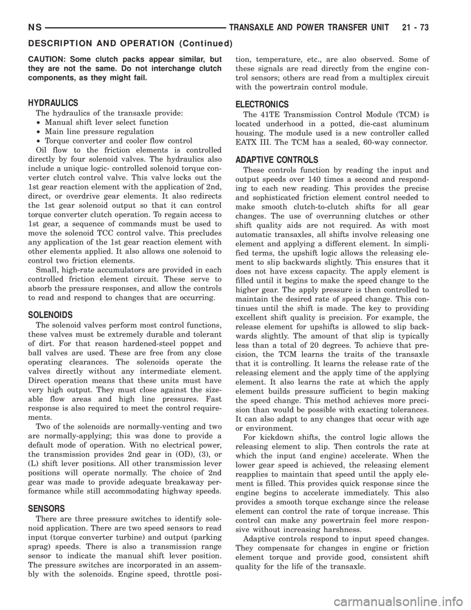
they are not the same. Do not interchange clutch
components, as they might fail.
HYDRAULICS
The hydraulics of the transaxle provide:
²Manual shift lever select function
²Main line pressure regulation
²Torque converter and cooler flow control
Oil flow to the friction elements is controlled
directly by four solenoid valves. The hydraulics also
include a unique logic- controlled solenoid torque con-
verter clutch control valve. This valve locks out the
1st gear reaction element with the application of 2nd,
direct, or overdrive gear elements. It also redirects
the 1st gear solenoid output so that it can control
torque converter clutch operation. To regain access to
1st gear, a sequence of commands must be used to
move the solenoid TCC control valve. This precludes
any application of the 1st gear reaction element with
other elements applied. It also allows one solenoid to
control two friction elements.
Small, high-rate accumulators are provided in each
controlled friction element circuit. These serve to
absorb the pressure responses, and allow the controls
to read and respond to changes that are occurring.
SOLENOIDS
The solenoid valves perform most control functions,
these valves must be extremely durable and tolerant
of dirt. For that reason hardened-steel poppet and
ball valves are used. These are free from any close
operating clearances. The solenoids operate the
valves directly without any intermediate element.
Direct operation means that these units must have
very high output. They must close against the size-
able flow areas and high line pressures. Fast
response is also required to meet the control require-
ments.
Two of the solenoids are normally-venting and two
are normally-applying; this was done to provide a
default mode of operation. With no electrical power,
the transmission provides 2nd gear in (OD), (3), or
(L) shift lever positions. All other transmission lever
positions will operate normally. The choice of 2nd
gear was made to provide adequate breakaway per-
formance while still accommodating highway speeds.
SENSORS
There are three pressure switches to identify sole-
noid application. There are two speed sensors to read
input (torque converter turbine) and output (parking
sprag) speeds. There is also a transmission range
sensor to indicate the manual shift lever position.
The pressure switches are incorporated in an assem-
bly with the solenoids. Engine speed, throttle posi-tion, temperature, etc., are also observed. Some of
these signals are read directly from the engine con-
trol sensors; others are read from a multiplex circuit
with the powertrain control module.
ELECTRONICS
The 41TE Transmission Control Module (TCM) is
located underhood in a potted, die-cast aluminum
housing. The module used is a new controller called
EATX III. The TCM has a sealed, 60-way connector.
ADAPTIVE CONTROLS
These controls function by reading the input and
output speeds over 140 times a second and respond-
ing to each new reading. This provides the precise
and sophisticated friction element control needed to
make smooth clutch-to-clutch shifts for all gear
changes. The use of overrunning clutches or other
shift quality aids are not required. As with most
automatic transaxles, all shifts involve releasing one
element and applying a different element. In simpli-
fied terms, the upshift logic allows the releasing ele-
ment to slip backwards slightly. This ensures that it
does not have excess capacity. The apply element is
filled until it begins to make the speed change to the
higher gear. The apply pressure is then controlled to
maintain the desired rate of speed change. This con-
tinues until the shift is made. The key to providing
excellent shift quality is precision. For example, the
release element for upshifts is allowed to slip back-
wards slightly. The amount of that slip is typically
less than a total of 20 degrees. To achieve that pre-
cision, the TCM learns the traits of the transaxle
that it is controlling. It learns the release rate of the
releasing element and the apply time of the applying
element. It also learns the rate at which the apply
element builds pressure sufficient to begin making
the speed change. This method achieves more preci-
sion than would be possible with exacting tolerances.
It can also adapt to any changes that occur with age
or environment.
For kickdown shifts, the control logic allows the
releasing element to slip. Then controls the rate at
which the input (and engine) accelerate. When the
lower gear speed is achieved, the releasing element
reapplies to maintain that speed until the apply ele-
ment is filled. This provides quick response since the
engine begins to accelerate immediately. This also
provides a smooth torque exchange since the release
element can control the rate of torque increase. This
control can make any powertrain feel more respon-
sive without increasing harshness.
Adaptive controls respond to input speed changes.
They compensate for changes in engine or friction
element torque and provide good, consistent shift
quality for the life of the transaxle.
NSTRANSAXLE AND POWER TRANSFER UNIT 21 - 73
DESCRIPTION AND OPERATION (Continued)