1996 CHRYSLER VOYAGER ABS
[x] Cancel search: ABSPage 1069 of 1938
scale provided on the package. Locate the band clos-
est to the same width. This band shows the amount
of clearance in thousandths of a millimeter. Differ-
ences in readings between the ends indicate the
amount of taper present. Record all readings taken.
Refer to Engine Specifications.Plastigage gener-
ally is accompanied by two scales. One scale is
in inches, the other is a metric scale.
(6) Plastigage is available in a variety of clearance
ranges. The 0.025-0.076 mm (.001-.003 in.) is usually
the most appropriate for checking engine bearing
proper specifications.
FITTING MAIN BEARINGS
Refer to the Engine General Information Section
for Measuring Main Bearings. For Crankshaft speci-
fications refer to Crankshaft Specification Chart.
CRANKSHAFT MAIN BEARINGS
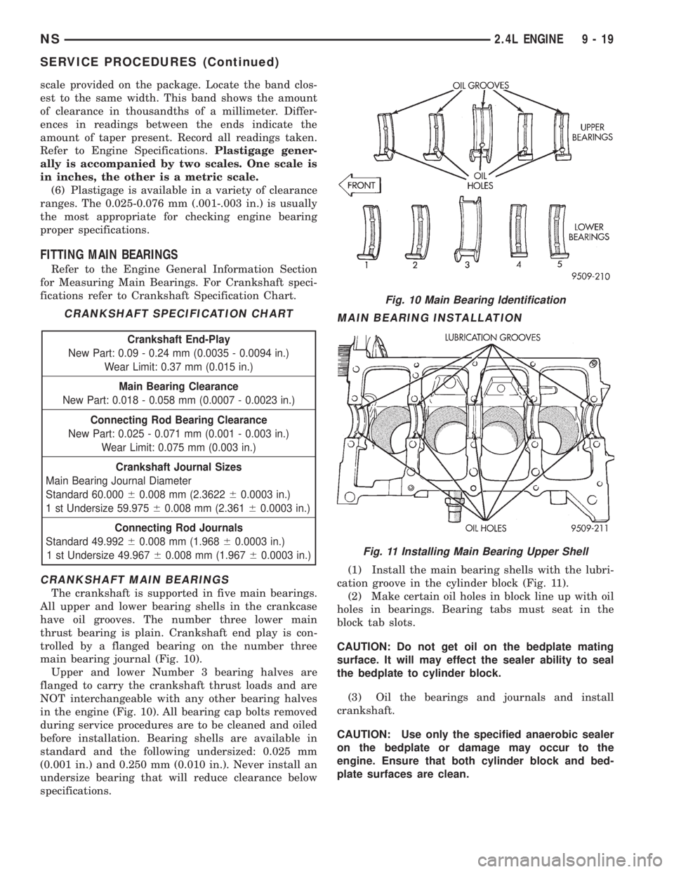
The crankshaft is supported in five main bearings.
All upper and lower bearing shells in the crankcase
have oil grooves. The number three lower main
thrust bearing is plain. Crankshaft end play is con-
trolled by a flanged bearing on the number three
main bearing journal (Fig. 10).
Upper and lower Number 3 bearing halves are
flanged to carry the crankshaft thrust loads and are
NOT interchangeable with any other bearing halves
in the engine (Fig. 10). All bearing cap bolts removed
during service procedures are to be cleaned and oiled
before installation. Bearing shells are available in
standard and the following undersized: 0.025 mm
(0.001 in.) and 0.250 mm (0.010 in.). Never install an
undersize bearing that will reduce clearance below
specifications.
MAIN BEARING INSTALLATION
(1) Install the main bearing shells with the lubri-
cation groove in the cylinder block (Fig. 11).
(2) Make certain oil holes in block line up with oil
holes in bearings. Bearing tabs must seat in the
block tab slots.
CAUTION: Do not get oil on the bedplate mating
surface. It will may effect the sealer ability to seal
the bedplate to cylinder block.
(3) Oil the bearings and journals and install
crankshaft.
CAUTION: Use only the specified anaerobic sealer
on the bedplate or damage may occur to the
engine. Ensure that both cylinder block and bed-
plate surfaces are clean.
CRANKSHAFT SPECIFICATION CHART
Crankshaft End-Play
New Part: 0.09 - 0.24 mm (0.0035 - 0.0094 in.)
Wear Limit: 0.37 mm (0.015 in.)
Main Bearing Clearance
New Part: 0.018 - 0.058 mm (0.0007 - 0.0023 in.)
Connecting Rod Bearing Clearance
New Part: 0.025 - 0.071 mm (0.001 - 0.003 in.)
Wear Limit: 0.075 mm (0.003 in.)
Crankshaft Journal Sizes
Main Bearing Journal Diameter
Standard 60.00060.008 mm (2.362260.0003 in.)
1 st Undersize 59.97560.008 mm (2.36160.0003 in.)
Connecting Rod Journals
Standard 49.99260.008 mm (1.96860.0003 in.)
1 st Undersize 49.96760.008 mm (1.96760.0003 in.)
Fig. 10 Main Bearing Identification
Fig. 11 Installing Main Bearing Upper Shell
NS2.4L ENGINE 9 - 19
SERVICE PROCEDURES (Continued)
Page 1070 of 1938
(4) Apply 1.5 to 2.0 mm (0.059 to 0.078 in.) bead
of anaerobic sealer MopartTorque Cure Gasket
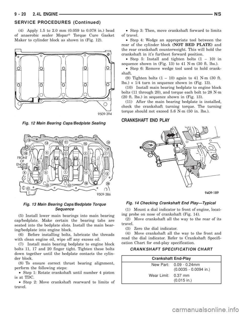
Maker to cylinder block as shown in (Fig. 12).
(5) Install lower main bearings into main bearing
cap/bedplate. Make certain the bearing tabs are
seated into the bedplate slots. Install the main bear-
ing/bedplate into engine block.
(6) Before installing bolts, lubricate the threads
with clean engine oil, wipe off any excess oil.
(7) Install main bearing bedplate to engine block
bolts 11, 17 and 20 finger tight. Tighten these bolts
down together until the bedplate contacts the cylin-
der block.
(8) To ensure correct thrust bearing alignment,
perform the following steps:
²Step 1: Rotate crankshaft until number 4 piston
is at TDC.
²Step 2: Move crankshaft rearward to limits of
travel.²Step 3: Then, move crankshaft forward to limits
of travel.
²Step 4: Wedge an appropriate tool between the
rear of the cylinder block(NOT BED PLATE)and
the rear crankshaft counterweight. This will hold the
crankshaft in it's furthest forward position.
²Step 5: Install and tighten bolts (1 ± 10) in
sequence shown in (Fig. 13) to 41 N´m (30 ft. lbs.).
²Step 6: Remove wedge tool used to hold crank-
shaft.
(9) Tighten bolts (1 ± 10) again to 41 N´m (30 ft.
lbs.) + 1/4 turn in sequence shown in (Fig. 13).
(10) Install main bearing bedplate to engine block
bolts (11 through 20), and torque each bolt to 28 N´m
(20 ft. lbs.) in sequence shown in (Fig. 13).
(11) After the main bearing bedplate is installed,
check the crankshaft turning torque. The turning
torque should not exceed 5.6 N´m (50 in. lbs.).
CRANKSHAFT END PLAY
(1) Mount a dial indicator to front of engine, locat-
ing probe on nose of crankshaft (Fig. 14).
(2) Move crankshaft all the way to the rear of its
travel.
(3) Zero the dial indicator.
(4) Move crankshaft all the way to the front and
read the dial indicator. Refer to Crankshaft Specifi-
cation Chart for end-play specification.
Fig. 12 Main Bearing Caps/Bedplate Sealing
Fig. 13 Main Bearing Caps/Bedplate Torque
SequenceFig. 14 Checking Crankshaft End PlayÐTypical
CRANKSHAFT SPECIFICATION CHART
Crankshaft End-Play
New Part: 0.09 - 0.24mm
(0.0035 - 0.0094 in.)
Wear Limit: 0.37 mm
(0.015 in.)
9 - 20 2.4L ENGINENS
SERVICE PROCEDURES (Continued)
Page 1096 of 1938
CRANKSHAFT
REMOVAL
NOTE: Crankshaft can not be removed when
engine is in vehicle.
(1) Remove oil filter and oil pan. Refer to proce-
dure outlined in this section.
(2) Remove Timing Belt Cover, Timing Belt and
Oil Pump. Refer to procedure outlined in this section.
(3) Remove Balance Shafts Assembly. Refer to pro-
cedure outlined in this section.
(4) Remove all main bearing cap bedplate bolts
from the engine block. Refer to procedure outlined in
this section.
(5) Using a mallet gently tap the bedplate loose
from the engine block dowel pins.
CAUTION: Do not pry up on one side of the bed-
plate. Damage may occur to cylinder block to bed-
plate alignment and thrust bearing.
(6) Bedplate should be removed evenly from the
cylinder block dowel pins to prevent damage to the
dowel pins and thrust bearing.
(7) Lift out crankshaft from cylinder block. Do not
damage the main bearings or journals when remov-
ing the crankshaft.
INSTALLATION
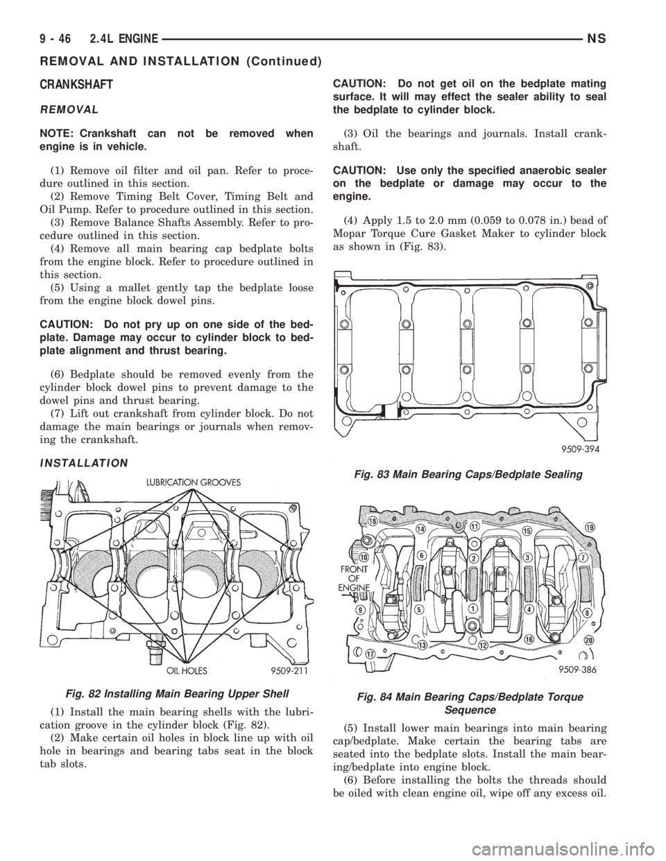
(1) Install the main bearing shells with the lubri-
cation groove in the cylinder block (Fig. 82).
(2) Make certain oil holes in block line up with oil
hole in bearings and bearing tabs seat in the block
tab slots.CAUTION: Do not get oil on the bedplate mating
surface. It will may effect the sealer ability to seal
the bedplate to cylinder block.
(3) Oil the bearings and journals. Install crank-
shaft.
CAUTION: Use only the specified anaerobic sealer
on the bedplate or damage may occur to the
engine.
(4) Apply 1.5 to 2.0 mm (0.059 to 0.078 in.) bead of
Mopar Torque Cure Gasket Maker to cylinder block
as shown in (Fig. 83).
(5) Install lower main bearings into main bearing
cap/bedplate. Make certain the bearing tabs are
seated into the bedplate slots. Install the main bear-
ing/bedplate into engine block.
(6) Before installing the bolts the threads should
be oiled with clean engine oil, wipe off any excess oil.
Fig. 82 Installing Main Bearing Upper Shell
Fig. 83 Main Bearing Caps/Bedplate Sealing
Fig. 84 Main Bearing Caps/Bedplate Torque
Sequence
9 - 46 2.4L ENGINENS
REMOVAL AND INSTALLATION (Continued)
Page 1112 of 1938
front seal is retained in the oil pump case and the
rear is retained in a block-mounted housing.
PISTONS:Are aluminum alloy with a steel strut,
short height, and thin wall so as to be autothermic
and light weight. The piston head with valve
recesses, in combination with the cylinder head,
forms a compact spherical head with clearance for
total valve lift with pistons at top dead center. The
piston skirt, top and second ring lands are finished to
a tapered roughness for oil retention and high resis-
tance to scuffing. Piston pins, pressed into place, join
the pistons to the connecting rods.
CYLINDER HEAD:The alloy cylinder heads fea-
ture cross-flow type intake and exhaust ports. Valve
guides and inserts are hardened cast iron. Valves of
heat resistance steel are arranged in a V with each
camshaft on center. To improve combustion speed the
chambers are a compact spherical design with a
squish area of approximately 30 percent of the piston
top area. The cylinder heads are common to either
cylinder bank by reversing the direction of installa-
tion.
CAMSHAFTS:Two overhead camshafts provide
valve actuation, one front (radiator side of cylinder
bank) and one rear. The front camshaft is provided
with a distributor drive and is longer. Both cam-
shafts are supported by four bearing journals, thrust
for the front camshaft is taken at journal two and
the rear at journal three. Front and rear camshaft
driving sprockets are interchangeable. The sprockets
and the engine water pump are driven by a single
notched timing belt.
ROCKER ARM SHAFTS:The shafts are retained
by the camshaft bearing journal caps. Four shafts are
used, one for each intake and exhaust rocker arm
assembly on each cylinder head. The hollow shafts
provide a duct for lubricating oil flow from the cylin-
der head to the valve mechanisms.
ROCKER ARMS:Are of light weight die-cast with
roller type follower operating against the cam shaft.
The valve actuating end of the rocker arms are
machined to retain hydraulic lash adjusters, elimi-
nating valve lash adjustment.
VALVES:Are made of heat resistant steel, valve
springs are especially designed to be short. The valve
spring wire cross-section is oval shaped and provides
the same spring tension as longer springs. Valve
spring retainers, locks and seals are conventional.
INTAKE MANIFOLD:The aluminum alloy mani-
fold is a cross type with long runners to improve
inertia. The runners, attaching below at the cylinder
head, also attach above and support an air plenum.
The air plenum chamber absorbs air pulsations cre-
ated during the suction phase of each cylinder.
EXHAUST MANIFOLDS:Both manifolds are a
log style made of ductile cast iron. Exhaust gasses,collected from the front cylinder bank, leave the front
manifold through an end outlet and are fed through
an upper crossover tube to the rear manifold. The
collected exhaust from both manifolds are combined,
and exit to the exhaust pipe through an articulated
joint.
DIAGNOSIS AND TESTING
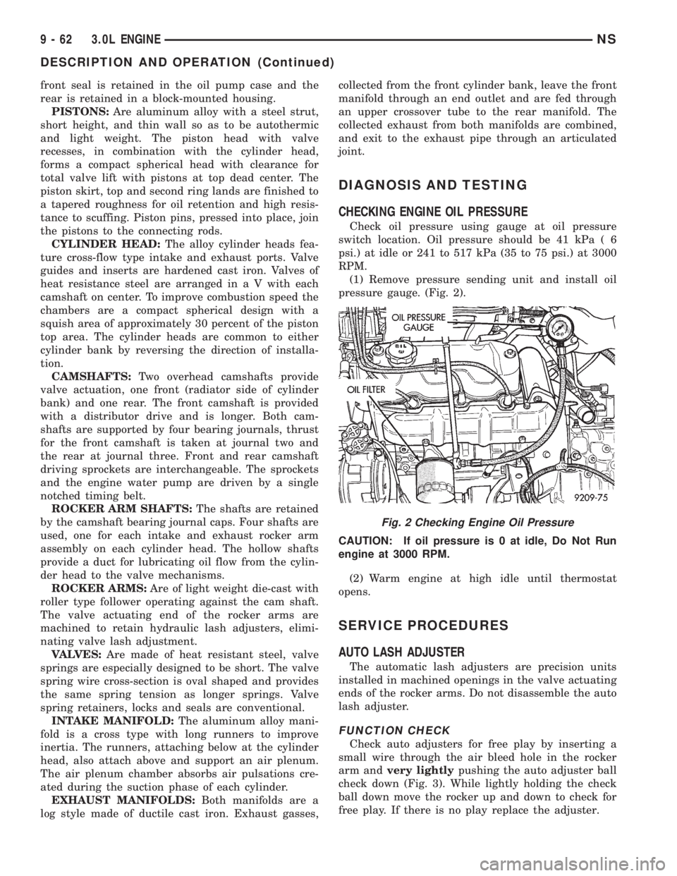
CHECKING ENGINE OIL PRESSURE
Check oil pressure using gauge at oil pressure
switch location. Oil pressure should be 41 kPa ( 6
psi.) at idle or 241 to 517 kPa (35 to 75 psi.) at 3000
RPM.
(1) Remove pressure sending unit and install oil
pressure gauge. (Fig. 2).
CAUTION: If oil pressure is 0 at idle, Do Not Run
engine at 3000 RPM.
(2) Warm engine at high idle until thermostat
opens.
SERVICE PROCEDURES
AUTO LASH ADJUSTER
The automatic lash adjusters are precision units
installed in machined openings in the valve actuating
ends of the rocker arms. Do not disassemble the auto
lash adjuster.
FUNCTION CHECK
Check auto adjusters for free play by inserting a
small wire through the air bleed hole in the rocker
arm andvery lightlypushing the auto adjuster ball
check down (Fig. 3). While lightly holding the check
ball down move the rocker up and down to check for
free play. If there is no play replace the adjuster.
Fig. 2 Checking Engine Oil Pressure
9 - 62 3.0L ENGINENS
DESCRIPTION AND OPERATION (Continued)
Page 1132 of 1938
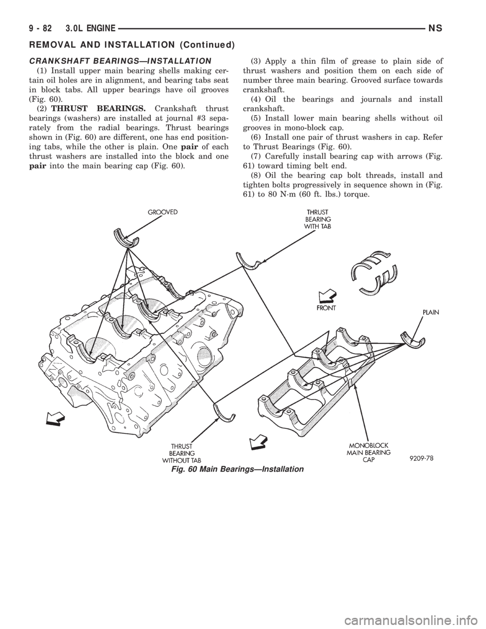
CRANKSHAFT BEARINGSÐINSTALLATION
(1) Install upper main bearing shells making cer-
tain oil holes are in alignment, and bearing tabs seat
in block tabs. All upper bearings have oil grooves
(Fig. 60).
(2)THRUST BEARINGS.Crankshaft thrust
bearings (washers) are installed at journal #3 sepa-
rately from the radial bearings. Thrust bearings
shown in (Fig. 60) are different, one has end position-
ing tabs, while the other is plain. Onepairof each
thrust washers are installed into the block and one
pairinto the main bearing cap (Fig. 60).(3) Apply a thin film of grease to plain side of
thrust washers and position them on each side of
number three main bearing. Grooved surface towards
crankshaft.
(4) Oil the bearings and journals and install
crankshaft.
(5) Install lower main bearing shells without oil
grooves in mono-block cap.
(6) Install one pair of thrust washers in cap. Refer
to Thrust Bearings (Fig. 60).
(7) Carefully install bearing cap with arrows (Fig.
61) toward timing belt end.
(8) Oil the bearing cap bolt threads, install and
tighten bolts progressively in sequence shown in (Fig.
61) to 80 N´m (60 ft. lbs.) torque.
Fig. 60 Main BearingsÐInstallation
9 - 82 3.0L ENGINENS
REMOVAL AND INSTALLATION (Continued)
Page 1200 of 1938
CAUTION: Do not pry up on one side of the bed-
plate. Damage may occur to cylinder block and bed-
plate alignment.(7) Bedplate should be removed evenly from the
cylinder block dowel pins.
(8) Lift out crankshaft from cylinder block. Be sure
not to damage the main bearings or journals when
removing the crankshaft.
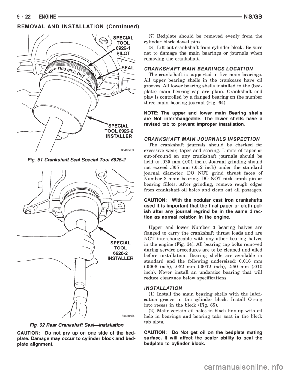
CRANKSHAFT MAIN BEARINGS LOCATION
The crankshaft is supported in five main bearings.
All upper bearing shells in the crankcase have oil
grooves. All lower bearing shells installed in the (bed-
plate) main bearing cap are plain. Crankshaft end
play is controlled by a flanged bearing on the number
three main bearing journal (Fig. 64).
NOTE: The upper and lower main Bearing shells
are Not interchangeable. The lower shells have a
revised tab to prevent improper installation.
CRANKSHAFT MAIN JOURNALS INSPECTION
The crankshaft journals should be checked for
excessive wear, taper and scoring. Limits of taper or
out-of-round on any crankshaft journals should be
held to .025 mm (.001 inch). Journal grinding should
not exceed .305 mm (.012 inch) under the standard
journal diameter. DO NOT grind thrust faces of
Number 3 main bearing. DO NOT nick crank pin or
bearing fillets. After grinding, remove rough edges
from crankshaft oil holes and clean out all passages.
CAUTION: With the nodular cast iron crankshafts
used it is important that the final paper or cloth pol-
ish after any journal regrind be in the same direc-
tion as normal rotation in the engine.
Upper and lower Number 3 bearing halves are
flanged to carry the crankshaft thrust loads and are
NOT interchangeable with any other bearing halves
in the engine (Fig. 64). All bearing cap bolts removed
during service procedures are to be cleaned and oiled
before installation. Bearing shells are available in
standard and the following undersized: 0.016 mm
(.0006 inch), .032 mm (.0012 inch), .250 mm (.010
inch). Never install an undersize bearing that will
reduce clearance below specifications.
INSTALLATION
(1) Install the main bearing shells with the lubri-
cation groove in the cylinder block. Install O-ring
into recess in the block (Fig. 65).
(2) Make certain oil holes in block line up with oil
hole in bearings and bearing tabs seat in the block
tab slots.
CAUTION: Do Not get oil on the bedplate mating
surface. It will affect the sealer ability to seal the
bedplate to cylinder block.
Fig. 61 Crankshaft Seal Special Tool 6926-2
Fig. 62 Rear Crankshaft SealÐInstallation
9 - 22 ENGINENS/GS
REMOVAL AND INSTALLATION (Continued)
Page 1201 of 1938
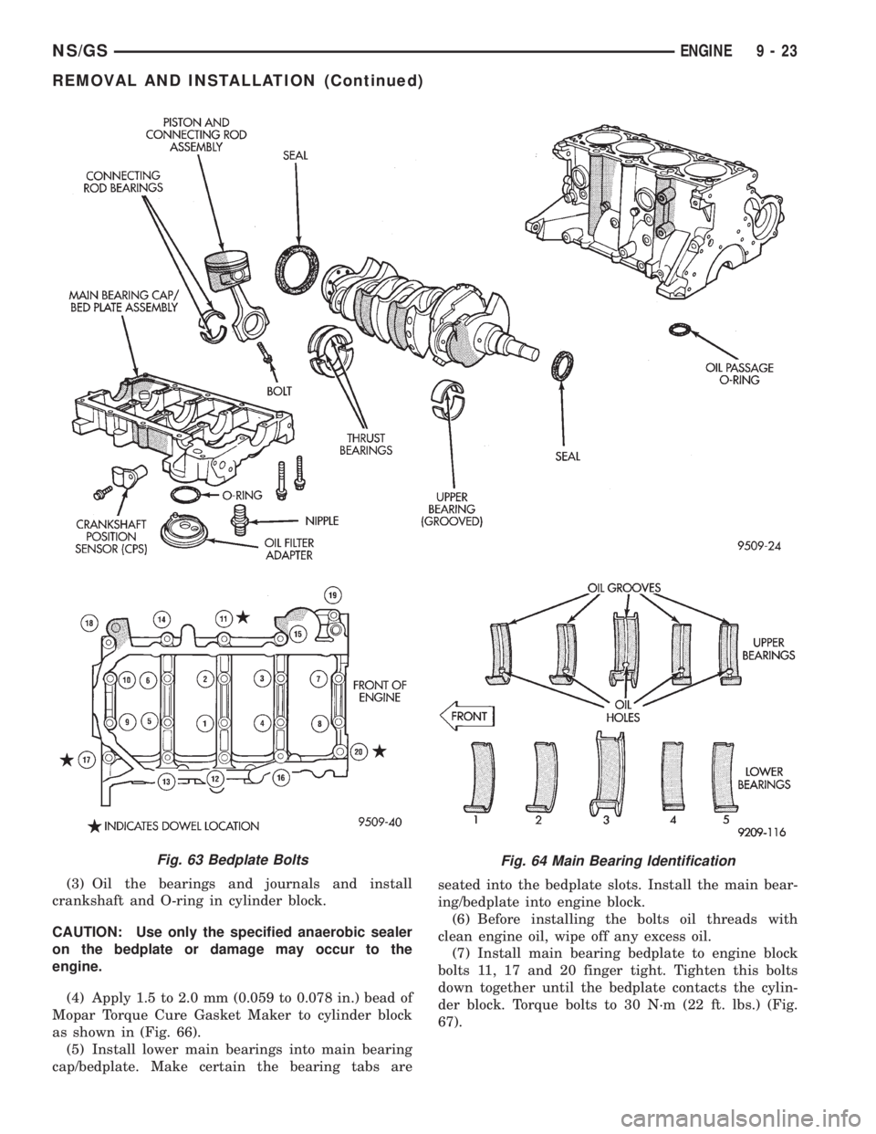
(3) Oil the bearings and journals and install
crankshaft and O-ring in cylinder block.
CAUTION: Use only the specified anaerobic sealer
on the bedplate or damage may occur to the
engine.
(4) Apply 1.5 to 2.0 mm (0.059 to 0.078 in.) bead of
Mopar Torque Cure Gasket Maker to cylinder block
as shown in (Fig. 66).
(5) Install lower main bearings into main bearing
cap/bedplate. Make certain the bearing tabs areseated into the bedplate slots. Install the main bear-
ing/bedplate into engine block.
(6) Before installing the bolts oil threads with
clean engine oil, wipe off any excess oil.
(7) Install main bearing bedplate to engine block
bolts 11, 17 and 20 finger tight. Tighten this bolts
down together until the bedplate contacts the cylin-
der block. Torque bolts to 30 N´m (22 ft. lbs.) (Fig.
67).
Fig. 63 Bedplate BoltsFig. 64 Main Bearing Identification
NS/GSENGINE 9 - 23
REMOVAL AND INSTALLATION (Continued)
Page 1265 of 1938
CAUTION: When servicing, care must be exercised
not to dent or bend the bellows of the flex-joint.
Should this occur, the flex-joint will eventually fail
and require the catalytic converter be replaced.
DESCRIPTION AND OPERATION
INTAKE/EXHAUST MANIFOLDÐ2.4L ENGINE
The intake manifold is a tuned two-piece alumi-
num casting with individual primary runners leading
from a plenum to the cylinders. The manifold is
designed to boost torque which is desired for excel-
lent engine response and usable power output.
The exhaust manifold is made of nodular cast iron
for strength and high temperatures.
INTAKE/EXHAUST MANIFOLDÐ3.0L ENGINE
The aluminum alloy manifold is a cross type with
long runners to improve air flow. The runners,
attaching below at the cylinder head, also attach
above and support an air plenum. The air plenum
chamber absorbs air pulsations created during the
suction phase of each cylinder.Both exhaust manifolds are a log style made of
ductile cast iron. Exhaust gasses, collected from the
front cylinder bank, leave the front manifold through
an end outlet and are fed through an upper crossover
tube to the rear manifold. The collected exhaust from
both manifolds are combined at the exhaust outlet, to
the exhaust pipe.
INTAKE/EXHAUST MANIFOLDÐ3.3/3.8L ENGINES
The intake manifold is a tuned two-piece semi-per-
manent mold aluminum casting with individual pri-
mary runners leading from a plenum to the
cylinders. The manifold is designed to boost torque in
the 3600 rpm range and contributes to the engine's
broad, flat torque curve, which was desired for excel-
lent engine tractability, response and usable power
output.
The intake manifold is also cored with upper level
EGR passages for balanced cylinder to cylinder EGR
distribution.
The exhaust manifolds are log type with a cross-
over and are attached directly to the cylinder heads.
They are made from nodular cast iron.
DIAGNOSIS AND TESTING
EXHAUST SYSTEM
CONDITION POSSIBLE CAUSES CORRECTION
EXCESSIVE EXHAUST
NOISE (UNDER HOOD)1. Exhaust manifold cracked or broken. 1. Replace manifold.
2. Manifold to cylinder head leak. 2. Tighten manifold and/or replace gasket.
3. EGR Valve to manifold gasket leakage. 3. Tighten fasteners or replace gasket.
4. EGR Valve to EGR tube gasket
leakage.4. Tighten fasteners or replace gasket.
5. EGR tube to manifold tube leakage. 5. Tighten tube nut.
6. Exhaust flex-joint to manifold leak. 6. Tighten joint fasteners and/or replace
gasket.
7. Exhaust flex-joint. 7. Replace catalytic converter assembly.
8. Pipe and shell noise from front exhaust
pipe.8. Characteristic of single wall pipe.
EXCESSIVE EXHAUST
NOISE1. Leak at exhaust pipe joints. 1. Tighten clamps at leaking joints.
2. Burned or rusted out muffler assembly
or exhaust pipe.2. Replace muffler resonator tailpipe
assembly or exhaust pipe with catalytic
converter assembly.
3. Burned or rusted out resonator. 3. Replace muffler resonator tailpipe
assembly.
4. Restriction in exhaust system. 4. Remove restriction, if possible, or
replace as necessary.
5. Converter material in muffler. 5. Replace muffler and converter
assemblies. Check fuel injection and
ignition systems for proper operation.
NSEXHAUST SYSTEM AND INTAKE MANIFOLD 11 - 3
GENERAL INFORMATION (Continued)