1996 CHRYSLER VOYAGER ABS
[x] Cancel search: ABSPage 477 of 1938

BULB APPLICATION
INDEX
page page
GENERAL INFORMATION
INTRODUCTION......................... 25SPECIFICATIONS
EXTERIOR LAMP BULBS.................. 25
INTERIOR LAMP BULBS.................. 25
GENERAL INFORMATION
INTRODUCTION
The following Bulb Application Tables list the lamp
title on the left side of the column and trade number
or part number on the right.
CAUTION: Do not use bulbs that have a higher
candle power than the bulb listed in the Bulb Appli-
cation Table. Damage to lamp can result.
Do not touch halogen bulbs with fingers or other
possibly oily surfaces. Bulb life will be reduced.
If a halogen bulb is contaminated with oil, clean
bulb with denatured alcohol or ammonia based sol-
vent.
SPECIFICATIONS
EXTERIOR LAMP BULBS
LAMP BULB
Back-up...............................3057
CHMSL................................921
Fog Lamp...............................H3
FogLamp±T&C ........................9040
Headlamp..............................9007
Headlamp high beam ± T&C...............9005
Headlamp low beam ± T&C............9005 SLL
License Plate............................168
Parking/Turn Signal/Front Side Marker. . . .3157NA
Parking/Turn Signal ± T&C............4157NAK
Tail, Stop, Turn Signal and Side Marker......3057
Front Side Marker......................194NA
INTERIOR LAMP BULBS
LAMP BULB
ABS.................................PC194
AirBag ..............................PC194
Alarm Set (Security)....................PC194
Brake Warning.........................PC194
Center/Rear Reading Lamps.................578
Center/Rear Dome Lamps...................579
Check Engine Ind.......................PC194
Front Door Courtesy.......................567
Door Ajar Ind..........................PC194
Front Header Reading Lamp................567
Glove Box Lamp..........................194
High Beam Ind.........................PC194
Instrument Cluster.....................PC194
IP Bin/Ash Tray..........................161
Liftgate Flood Lamps......................567
Liftgate Ajar Ind.........................PC74
Low Fuel Ind..........................PC194
Oil Pressure Ind........................PC194
O/H Console Reading Lamps................579
Seat Belt Ind...........................PC74
Engine Temp Ind.......................PC194
Turn Signal...........................PC194
Engine Compartment Lamps................579
Visor Vanity Lamp....................6501966
Low Washer Fluid.......................PC74
Low Volts Warning.......................PC74
Cruise Indicator........................PC194
NSLAMPS 8L - 25
Page 490 of 1938

LICENSE PLATE LAMP BULB
REMOVAL
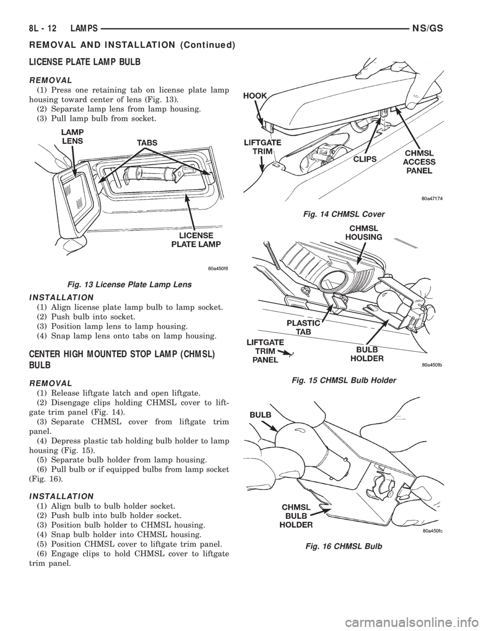
(1) Press one retaining tab on license plate lamp
housing toward center of lens (Fig. 13).
(2) Separate lamp lens from lamp housing.
(3) Pull lamp bulb from socket.
INSTALLATION
(1) Align license plate lamp bulb to lamp socket.
(2) Push bulb into socket.
(3) Position lamp lens to lamp housing.
(4) Snap lamp lens onto tabs on lamp housing.
CENTER HIGH MOUNTED STOP LAMP (CHMSL)
BULB
REMOVAL
(1) Release liftgate latch and open liftgate.
(2) Disengage clips holding CHMSL cover to lift-
gate trim panel (Fig. 14).
(3) Separate CHMSL cover from liftgate trim
panel.
(4) Depress plastic tab holding bulb holder to lamp
housing (Fig. 15).
(5) Separate bulb holder from lamp housing.
(6) Pull bulb or if equipped bulbs from lamp socket
(Fig. 16).
INSTALLATION
(1) Align bulb to bulb holder socket.
(2) Push bulb into bulb holder socket.
(3) Position bulb holder to CHMSL housing.
(4) Snap bulb holder into CHMSL housing.
(5) Position CHMSL cover to liftgate trim panel.
(6) Engage clips to hold CHMSL cover to liftgate
trim panel.
Fig. 13 License Plate Lamp Lens
Fig. 14 CHMSL Cover
Fig. 15 CHMSL Bulb Holder
Fig. 16 CHMSL Bulb
8L - 12 LAMPSNS/GS
REMOVAL AND INSTALLATION (Continued)
Page 495 of 1938

BULB APPLICATION
INDEX
page page
GENERAL INFORMATION
INTRODUCTION....................... 17
CLEANING AND INSPECTION
HEADLAMP CLEANING.................. 17SPECIFICATIONS
EXTERIOR LAMP BULBS................. 17
INTERIOR LAMP BULBS................. 17
GENERAL INFORMATION
INTRODUCTION
The following Bulb Application Tables list the lamp
title on the left side of the column and trade number
or part number on the right.
CAUTION: Do not use bulbs that have a higher
candle power than the bulb listed in the Bulb Appli-
cation Table. Damage to lamp can result.
Do not touch halogen bulbs with fingers or other
possibly oily surfaces. Bulb life will be reduced.
If a halogen bulb is contaminated with oil, clean
bulb with denatured alcohol or ammonia based sol-
vent.
CLEANING AND INSPECTION
HEADLAMP CLEANING
This vehicle is equipped with plastic headlights
that are lighter and less susceptible to stone break-
age than glass headlights.
This plastic is not as scratch resistant as glass and
therefore a different lens cleaning procedures must
be followed.
To minimize the possibility of scratching the lenses
and reducing light output, avoid wiping with a dry
cloth. To remove road dirt, wash with a mild soap
solution followed by rinsing with water.
Do not use abrasive cleaning components, solvents,
steel wool or other aggressive material to clean the
lenses.
SPECIFICATIONS
EXTERIOR LAMP BULBS
LAMP BULB
Back-up.............................P21W
CHMSL (Non-Solar Tint)................P21W
CHMSL (Solar Tint)....................R10WLAMP BULB
Fog Lamp..............................H3
Headlamp..............................H4
License Plate..........................C5W
Front Turn Signal....................PY21W
Citylight..............................T4W
Front Side Repeater.....................T4W
Tail, Stop...........................P21/5W
Rear Turn Signal......................P21W
Rear Fog Lamp........................P21W
INTERIOR LAMP BULBS
LAMP BULB
ABS ................................PC194
AirBag .............................PC194
Alarm Set (Security/Immobilzer)..........PC194
Brake Warning.......................PC194
Center/Rear Reading Lamps...............578
Center/Rear Dome Lamps.................579
Cruise Indicator.......................PC194
Door Ajar Indicator....................PC194
Engine Compartment Lamps...............579
Engine Temp Indicator.................PC194
Front Door Courtesy......................567
Glove Box Lamp.........................194
Glow Plug Indicator (Diesel Engine Only) . . . PC194
High Beam Indicator...................PC194
Instrument Cluster....................PC194
IP/Ash Tray (Left Hand Drive Only).........161
Liftgate Flood Lamps.....................567
Liftgate Ajar Indicator...................PC74
Low Coolant Level (Diesel Engine Only).....PC74
Low Fuel Indicator....................PC194
Low Volts Warning.....................PC74
Low Washer Fluid......................PC74
Oil Pressure Indicator..................PC194
O/H Console Reading Lamps...............579
Seat Belt Indicator (Except Diesel).........PC74
Service Engine Soon...................PC194
Turn Signal..........................PC194
Visor Vanity Lamp...................6501966
NS/GSLAMPS 8L - 17
Page 501 of 1938

CLOCKSPRING
WARNING: DISCONNECT AND ISOLATE THE BAT-
TERY NEGATIVE CABLE BEFORE BEGINNING AIR-
BAG SYSTEM COMPONENT SERVICE
PROCEDURES. THIS WILL DISABLE THE AIRBAG
SYSTEM. FAILURE TO DISCONNECT THE BATTERY
COULD RESULT IN ACCIDENTAL AIRBAG DEPLOY-
MENT AND POSSIBLE PERSONAL INJURY. ALLOW
SYSTEM CAPACITOR TO DISCHARGE FOR TWO
MINUTES BEFORE REMOVING AIRBAG COMPO-
NENTS.
REMOVAL
(1) Position steering wheel and front wheels
straight ahead.
(2) Release hood latch and open hood.
(3) Disconnect and isolate battery negative cable.
Allow at least two minutes for the reserve capacitor
in the ACM to discharge.
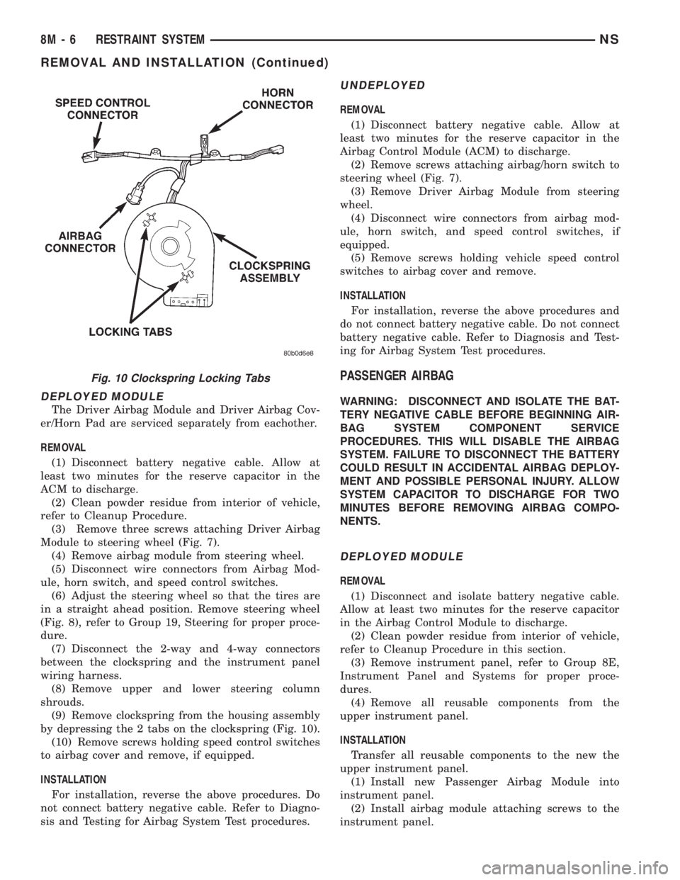
(4) Remove driver airbag from steering wheel (Fig.
7).
(5) Disconnect wire connectors from back of airbag
module.
(6) Remove steering wheel (Fig. 8).
(7) Remove steering column shrouds (Fig. 9).
(8) Disconnect 2-way and 4-way connectors
between the clockspring and the instrument panel
wiring harness.
(9) Remove clockspring from housing assembly by
depressing the two tabs on the clockspring (Fig. 10)
INSTALLATION
For installation, reverse the above procedures. Do
not connect battery negative cable. Refer to Diagno-
sis and Testing for Airbag System Test procedures.
DRIVER AIRBAG MODULE
WARNING: DISCONNECT AND ISOLATE THE BAT-
TERY NEGATIVE CABLE BEFORE BEGINNING AIR-
BAG SYSTEM COMPONENT SERVICE
PROCEDURES. THIS WILL DISABLE THE AIRBAG
SYSTEM. FAILURE TO DISCONNECT THE BATTERY
COULD RESULT IN ACCIDENTAL AIRBAG DEPLOY-
MENT AND POSSIBLE PERSONAL INJURY. ALLOW
SYSTEM CAPACITOR TO DISCHARGE FOR TWO
MINUTES BEFORE REMOVING AIRBAG COMPO-
NENTS.Fig. 7 Airbag/Horn Switch
Fig. 8 Steering Wheel
Fig. 9 Airbag Clockspring
NSRESTRAINT SYSTEM 8M - 5
REMOVAL AND INSTALLATION (Continued)
Page 502 of 1938

DEPLOYED MODULE
The Driver Airbag Module and Driver Airbag Cov-
er/Horn Pad are serviced separately from eachother.
REMOVAL
(1) Disconnect battery negative cable. Allow at
least two minutes for the reserve capacitor in the
ACM to discharge.
(2) Clean powder residue from interior of vehicle,
refer to Cleanup Procedure.
(3) Remove three screws attaching Driver Airbag
Module to steering wheel (Fig. 7).
(4) Remove airbag module from steering wheel.
(5) Disconnect wire connectors from Airbag Mod-
ule, horn switch, and speed control switches.
(6) Adjust the steering wheel so that the tires are
in a straight ahead position. Remove steering wheel
(Fig. 8), refer to Group 19, Steering for proper proce-
dure.
(7) Disconnect the 2-way and 4-way connectors
between the clockspring and the instrument panel
wiring harness.
(8) Remove upper and lower steering column
shrouds.
(9) Remove clockspring from the housing assembly
by depressing the 2 tabs on the clockspring (Fig. 10).
(10) Remove screws holding speed control switches
to airbag cover and remove, if equipped.
INSTALLATION
For installation, reverse the above procedures. Do
not connect battery negative cable. Refer to Diagno-
sis and Testing for Airbag System Test procedures.
UNDEPLOYED
REMOVAL
(1) Disconnect battery negative cable. Allow at
least two minutes for the reserve capacitor in the
Airbag Control Module (ACM) to discharge.
(2) Remove screws attaching airbag/horn switch to
steering wheel (Fig. 7).
(3) Remove Driver Airbag Module from steering
wheel.
(4) Disconnect wire connectors from airbag mod-
ule, horn switch, and speed control switches, if
equipped.
(5) Remove screws holding vehicle speed control
switches to airbag cover and remove.
INSTALLATION
For installation, reverse the above procedures and
do not connect battery negative cable. Do not connect
battery negative cable. Refer to Diagnosis and Test-
ing for Airbag System Test procedures.
PASSENGER AIRBAG
WARNING: DISCONNECT AND ISOLATE THE BAT-
TERY NEGATIVE CABLE BEFORE BEGINNING AIR-
BAG SYSTEM COMPONENT SERVICE
PROCEDURES. THIS WILL DISABLE THE AIRBAG
SYSTEM. FAILURE TO DISCONNECT THE BATTERY
COULD RESULT IN ACCIDENTAL AIRBAG DEPLOY-
MENT AND POSSIBLE PERSONAL INJURY. ALLOW
SYSTEM CAPACITOR TO DISCHARGE FOR TWO
MINUTES BEFORE REMOVING AIRBAG COMPO-
NENTS.
DEPLOYED MODULE
REMOVAL
(1) Disconnect and isolate battery negative cable.
Allow at least two minutes for the reserve capacitor
in the Airbag Control Module to discharge.
(2) Clean powder residue from interior of vehicle,
refer to Cleanup Procedure in this section.
(3) Remove instrument panel, refer to Group 8E,
Instrument Panel and Systems for proper proce-
dures.
(4) Remove all reusable components from the
upper instrument panel.
INSTALLATION
Transfer all reusable components to the new the
upper instrument panel.
(1) Install new Passenger Airbag Module into
instrument panel.
(2) Install airbag module attaching screws to the
instrument panel.
Fig. 10 Clockspring Locking Tabs
8M - 6 RESTRAINT SYSTEMNS
REMOVAL AND INSTALLATION (Continued)
Page 528 of 1938

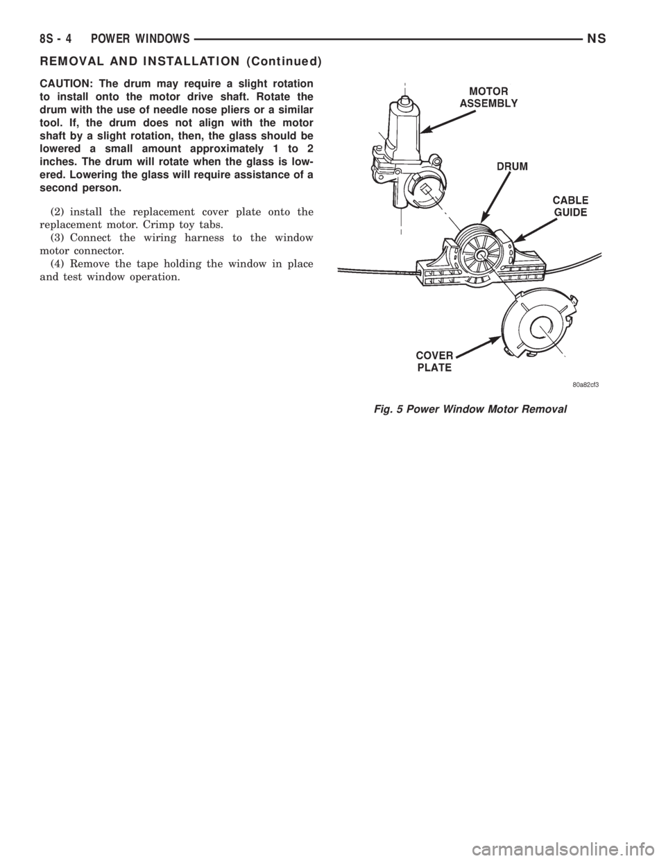
CAUTION: The drum may require a slight rotation
to install onto the motor drive shaft. Rotate the
drum with the use of needle nose pliers or a similar
tool. If, the drum does not align with the motor
shaft by a slight rotation, then, the glass should be
lowered a small amount approximately 1 to 2
inches. The drum will rotate when the glass is low-
ered. Lowering the glass will require assistance of a
second person.
(2) install the replacement cover plate onto the
replacement motor. Crimp toy tabs.
(3) Connect the wiring harness to the window
motor connector.
(4) Remove the tape holding the window in place
and test window operation.
Fig. 5 Power Window Motor Removal
8S - 4 POWER WINDOWSNS
REMOVAL AND INSTALLATION (Continued)
Page 556 of 1938

COMPASS MINI-TRIP COMPUTER (CMTC)
MODULE
REMOVAL
(1) Disconnect battery negative cable.
(2) Remove overhead console.
(3) Remove the six screws holding CMTC module
to overhead console (Fig. 6).
(4) Remove CMTC module from console.
INSTALLATION
For installation, reverse the above procedures.
COMPASS MINI-TRIP COMPUTER (CMTC) LAMP
BULBS
REMOVAL
(1) Remove overhead console.
(2) Rotate bulb socket counterclockwise one quar-
ter turn (Fig. 7).(3) Pull bulb socket from CMTC module.
INSTALLATION
For installation, reverse the above procedures.
FRONT HEADER READING/COURTESY LAMP
REMOVAL
(1) Place a small flat tool in the slot at the forward
edge of the lamp lens and twist (Fig. 8).
(2) Remove lens.
(3) Insert the tip of the tool under the inside, rear
edge of the reflector/light shield. Carefully pry reflec-
tor/light shield out.
(4) Remove the lamp by pressing forward the brass
terminal and rotating the lamp clockwise to remove.
INSTALLATION
For installation, reverse the above procedures.
When installing the lamp lens, first guide the switch
contact tab on the lens between the lamp switch
plunger and the lamp bezel. Then snap lens onto the
two lens pivots on the bezel.
OVERHEAD CONSOLE
REMOVAL
(1) Open the transmitter bin door (Fig. 9).
(2) Remove screw holding the overhead console to
the headliner. With the screw removed the console is
retained by one engagement tab located inside the
eyeglass storage bin.
(3) Open the eyeglass bin door.
(4) Press the retaining tab which is located
directly above the door latch.
(5) Lower rear of console away from headliner.
(6) Pull console rearward to disengage clips hold-
ing front of console to roof armature and lower con-
sole.
(7) Disconnect wire connectors from back of CMTC
and reading lamps. Ensure the connectors lock tabs
are fully depressed before disconnecting.
(8) Remove overhead console.
INSTALLATION
For installation, reverse the above procedures.
READING/COURTESY LAMP
Removal
(1) Using a trim stick, lightly pry outward the for-
ward end of reading lamp lens (Fig. 10).
(2) Rotate reading/courtesy lamp socket one quar-
ter turn counterclockwise.
(3) Pull socket out of lamp (Fig. 11).
(4) Pull lamp from socket.
Fig. 6 Compass Mini-Trip Computer
Fig. 7 CMTC Lamp Bulbs
8V - 6 OVERHEAD CONSOLENS
REMOVAL AND INSTALLATION (Continued)
Page 577 of 1938

8W-02 COMPONENT INDEX
Component Page
2-4 Pressure Switch.....................8W-31
2-4 Solenoid...........................8W-31
A/C Compressor Clutch..................8W-42
A/C Compressor Clutch Relay...........8W-10, 42
A/C Heater Control.....................8W-42
A/C On Indicator.......................8W-42
A/C Pressure Transducer..............8W-30, 42
A/C Switch............................8W-42
A/C Zone Door Actuator..................8W-42
ABS Warning Lamp..................8W-35, 46
Accelerator Pedal Position Sensor..........8W-30
Airbag Control Module...................8W-43
Airbag Indicator Lamp...................8W-43
Airbag Warning Lamp...................8W-46
All Wheel Drive Solenoid.................8W-31
Ambient Air Temperature Sensor...........8W-49
Ash Receiver Lamp.....................8W-44
Automatic Day/Night Mirror..............8W-44
Automatic Shut Down Relay............8W-10, 30
Splice Information......................8W-70
Back-Up Lamp.........................8W-51
Back-Up Switch.....................8W-44, 51
Battery...............................8W-20
Blend Door Actuator.....................8W-42
Body Control Module....................8W-45
Brake Pressure Switch...................8W-46
Brake Warning Lamp....................8W-46
Camshaft Position Sensor................8W-30
Center Dome Lamp.....................8W-44
Center High Mounted Stop Lamp..........8W-51
Cigar/Accessory Relay...................8W-41
Clockspring.......8W-10, 15, 30, 33, 39, 40, 41, 43
Cluster Illumination Lamps...............8W-40
Clutch Interlock Switch...............8W-12, 21
Clutch Interlock Switch Jumper......8W-12, 21, 31
Clutch Switch.......................8W-30, 33
Combination Flasher/DRL Module. . . .8W-50, 51, 52
Combination Relays.....................8W-54
Compass/Mini-Trip Computer..............8W-49
Control Sleeve Sensor....................8W-30
Controller Anti-Lock Brake...............8W-35
Courtesy Lamp Relay...........8W-10, 12, 44, 50
Crank Case Heater......................8W-30
Crankshaft Position Sensor...............8W-30
Cruise Indicator Lamp...................8W-40
Data Link Connector....................8W-30
Diesel Power Relay...................8W-10, 30
Dome Lamp Switch.....................8W-50
Door Ajar Indicator Lamp................8W-40
Door Ajar Switches................8W-39, 40, 44
Door Lock Relay........................8W-61
Speakers..............................8W-47Component Page
Door Unlock Relay......................8W-61
Oxygen Sensors........................8W-30
Door Ajar Switches.............8W-39, 40, 44, 45
Door Arm/Disarm Switches.............8W-39, 61
Door Courtesy Lamps....................8W-44
Door Lock Motors.......................8W-61
Door Lock Switches.....................8W-61
Door Unlock Relays.....................8W-61
Heated Seat Backs......................8W-63
Heated Seat Cushions...................8W-63
Heated Seat Modules....................8W-63
Heated Seat Switches....................8W-63
Power Mirrors.........................8W-62
Power Seat Switches....................8W-63
Power Window Switches..................8W-60
Seat Motors...........................8W-63
Window Motors........................8W-60
Radiator Fans.........................8W-42
Dump Solenoid.........................8W-33
EGR Solenoid..........................8W-30
Electric Wiper De-Icer...................8W-48
Electronic PRNDL Indicator...............8W-40
Engine Coolant Temperature Gauge.........8W-40
Engine Coolant Temperature Lamp.........8W-46
Engine Coolant Temperature Sensor........8W-30
Engine Oil Pressure Switch...............8W-46
Engine Speed Sensor....................8W-30
Engine Starter Motor....................8W-21
Engine Starter Motor Relay............8W-10, 21
Evap Leak Detection Pump...............8W-30
Evap/Purge Solenoid....................8W-30
Evaporator Temperature Sensor............8W-42
Express Down Module...................8W-60
Flexible Fuel Sensor.....................8W-30
Fog Lamps............................8W-50
Fog Lamp Relay........................8W-50
Front Blower Motor.....................8W-42
Front Blower Motor Relay.............8W-10, 42
Front Blower Motor Resistor Block.........8W-42
Front Cigar Lighter/Power Outlet..........8W-41
Front Reading Lamp Defeat Switch.........8W-44
Front Reading Lamps/Switch..............8W-44
Front Washer Motor.....................8W-53
Front Wiper Switch.....................8W-53
Fuel Gauge............................8W-40
Fuel Heater...........................8W-30
Fuel Heater Relay...................8W-10, 30
Fuel Injectors..........................8W-30
Fuel Pump Module......................8W-30
Fuel Pump Relay....................8W-10, 30
Fuel Quantity Actuator..................8W-30
Fuel Shutdown Solenoid..................8W-30
NS/GS8W - 02 COMPONENT INDEX 8W - 02 - 1