1996 CHRYSLER VOYAGER ABS
[x] Cancel search: ABSPage 1886 of 1938
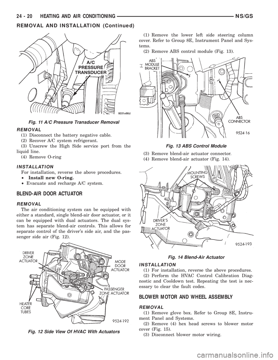
REMOVAL
(1) Disconnect the battery negative cable.
(2) Recover A/C system refrigerant.
(3) Unscrew the High Side service port from the
liquid line.
(4) Remove O-ring
INSTALLATION
For installation, reverse the above procedures.
²Install new O-ring.
²Evacuate and recharge A/C system.
BLEND-AIR DOOR ACTUATOR
REMOVAL
The air conditioning system can be equipped with
either a standard, single blend-air door actuator, or it
can be equipped with dual actuators. The dual sys-
tem has separate blend-air controls. This allows for
separate control of the driver's side air, and the pas-
senger side air (Fig. 12).(1) Remove the lower left side steering column
cover. Refer to Group 8E, Instrument Panel and Sys-
tems.
(2) Remove ABS control module (Fig. 13).
(3) Remove blend-air actuator connector.
(4) Remove blend-air actuator (Fig. 14).
INSTALLATION
(1) For installation, reverse the above procedures.
(2) Perform the HVAC Control Calibration Diag-
nostic and Cooldown test. Repeating the test is nec-
essary to clear the fault codes.
BLOWER MOTOR AND WHEEL ASSEMBLY
REMOVAL
(1) Remove glove box. Refer to Group 8E, Instru-
ment Panel and Systems.
(2) Remove (4) hex head screws to blower motor
cover (Fig. 15).
(3) Disconnect blower motor wiring.
Fig. 11 A/C Pressure Transducer Removal
Fig. 12 Side View Of HVAC With Actuators
Fig. 13 ABS Control Module
Fig. 14 Blend-Air Actuator
24 - 20 HEATING AND AIR CONDITIONINGNS/GS
REMOVAL AND INSTALLATION (Continued)
Page 1892 of 1938
(2) Hand-start the stud into the expansion valve
and torque to7-11N´m(64-96in.lbs.).
(3) Carefully install the expansion valve to the
sealing plate. Install the two screws and tighten 8 to
14 N´m (70 to 130 in. lbs.) torque.
(4) Carefully install the refrigerant lines and seal-
ing plate to the expansion valve. Install the nut and
tighten 20 to 26 N´m (170 to 230 in. lbs.) torque.
(5) Install the ground wire at dash panel.
(6) Pull generator back into the proper position for
bracket mounting.
(7) Install generator field wire connector.
(8) Install the upper generator bracket.
(9) Install accessory drive belt.
(10) Evacuate and recharge system.
(11) After expansion valve is installed, the system
is charged, and leaks have checked repeat the A/C
performance check.
FILTER-DRIER ASSEMBLY
REMOVAL
WARNING: THE REFRIGERATION SYSTEM MUST
BE COMPLETELY EMPTY BEFORE PROCEEDING
WITH THIS OPERATION.
(1) Recover A/C system refrigerant.
(2) Remove liquid line at filter-drier (Fig. 21).
(3) Remove the (2) bolts holding filter-drier bracket
to radiator fan module bracket.
(4) Remove the lower liquid line at condenser.
(5) Remove the upper radiator crossmember.
(6) Pull up on radiator and slide filter-drier from
the mounting location.
INSTALLATION
(1) Before installation, replace both refrigerant
line O-rings. Then reverse the above procedures.
(2) Evacuate and recharge system.
HEATER A/C UNIT HOUSING
REMOVAL
WARNING: IF EQUIPPED WITH AIR CONDITIONING,
THE REFRIGERATION SYSTEM MUST BE COM-
PLETELY EMPTY BEFORE PROCEEDING.
(1) Set parking brake.
(2) Disconnect battery negative cable.
(3) Using a refrigerant recovery machine, remove
refrigerant from the A/C system.
(4) Remove wiper module. Refer to Group 8K,
Windshield Wipers and Washers.
(5) Drain engine coolant. Remove heater hoses at
the heater core, refer to Heater Hoses Removal and
Installation procedures. Plug coolant lines.(6) Remove suction and liquid lines at the expan-
sion valve (Fig. 27).
(7) Remove the Instrument Panel Assembly. Refer
to Group 8E, Instrument Panel and Systems.
(8) Remove heater ducts.
(9) Disconnect the two upper mounts from the
upper reinforcement and the lower mount from the
tunnel.
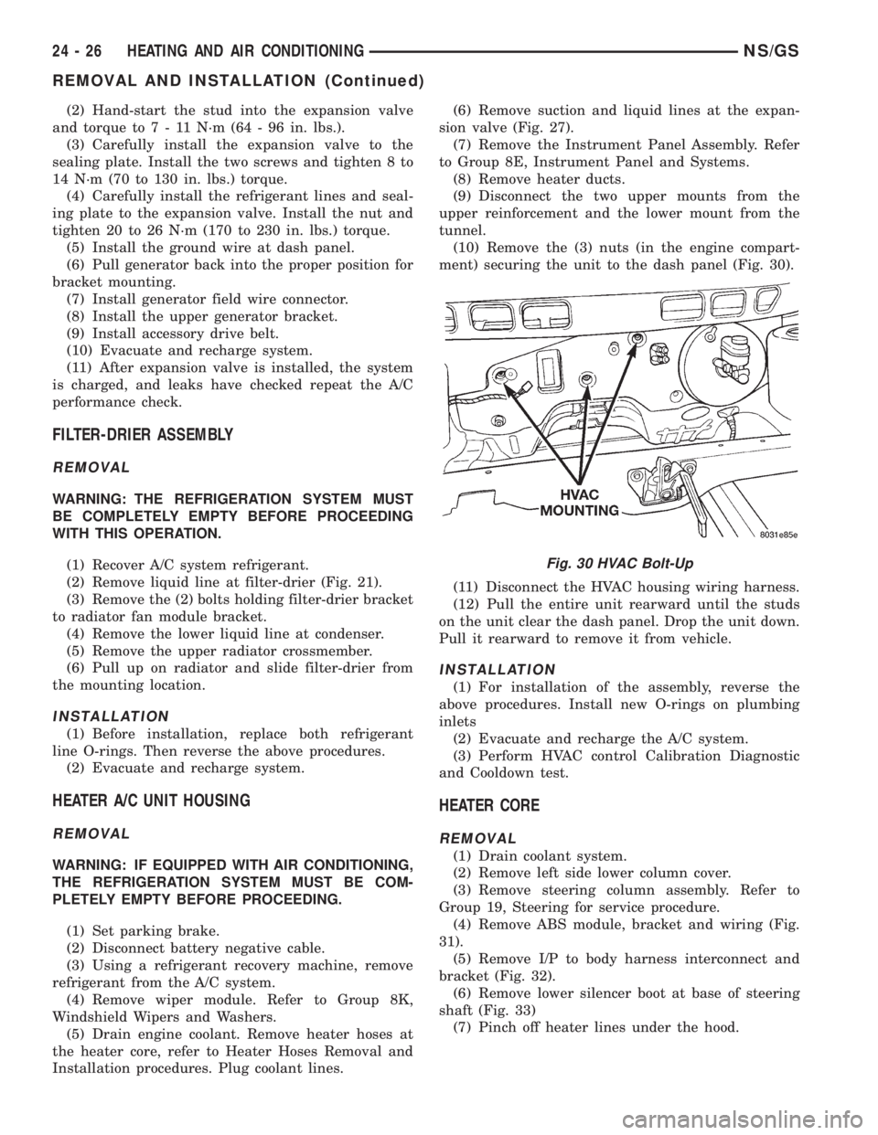
(10) Remove the (3) nuts (in the engine compart-
ment) securing the unit to the dash panel (Fig. 30).
(11) Disconnect the HVAC housing wiring harness.
(12) Pull the entire unit rearward until the studs
on the unit clear the dash panel. Drop the unit down.
Pull it rearward to remove it from vehicle.
INSTALLATION
(1) For installation of the assembly, reverse the
above procedures. Install new O-rings on plumbing
inlets
(2) Evacuate and recharge the A/C system.
(3) Perform HVAC control Calibration Diagnostic
and Cooldown test.
HEATER CORE
REMOVAL
(1) Drain coolant system.
(2) Remove left side lower column cover.
(3) Remove steering column assembly. Refer to
Group 19, Steering for service procedure.
(4) Remove ABS module, bracket and wiring (Fig.
31).
(5) Remove I/P to body harness interconnect and
bracket (Fig. 32).
(6) Remove lower silencer boot at base of steering
shaft (Fig. 33)
(7) Pinch off heater lines under the hood.
Fig. 30 HVAC Bolt-Up
24 - 26 HEATING AND AIR CONDITIONINGNS/GS
REMOVAL AND INSTALLATION (Continued)
Page 1893 of 1938
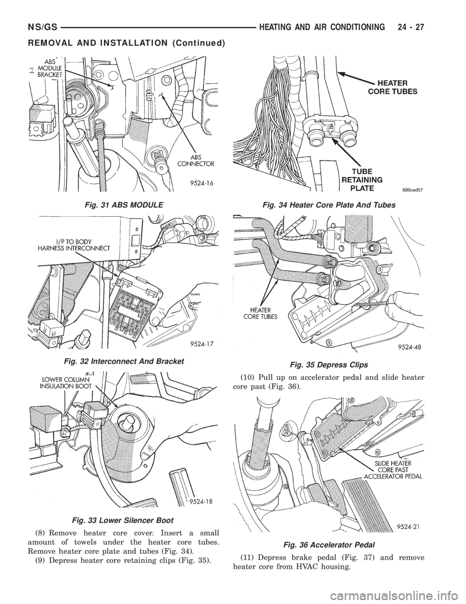
(8) Remove heater core cover. Insert a small
amount of towels under the heater core tubes.
Remove heater core plate and tubes (Fig. 34).
(9) Depress heater core retaining clips (Fig. 35).(10) Pull up on accelerator pedal and slide heater
core past (Fig. 36).
(11) Depress brake pedal (Fig. 37) and remove
heater core from HVAC housing.
Fig. 31 ABS MODULE
Fig. 32 Interconnect And Bracket
Fig. 33 Lower Silencer Boot
Fig. 34 Heater Core Plate And Tubes
Fig. 35 Depress Clips
Fig. 36 Accelerator Pedal
NS/GSHEATING AND AIR CONDITIONING 24 - 27
REMOVAL AND INSTALLATION (Continued)
Page 1895 of 1938
MODE DOOR ACTUATOR
REMOVAL
(1) Remove the lower left side steering column
cover. Refer to Group 8E, Instrument Panel and Sys-
tems.
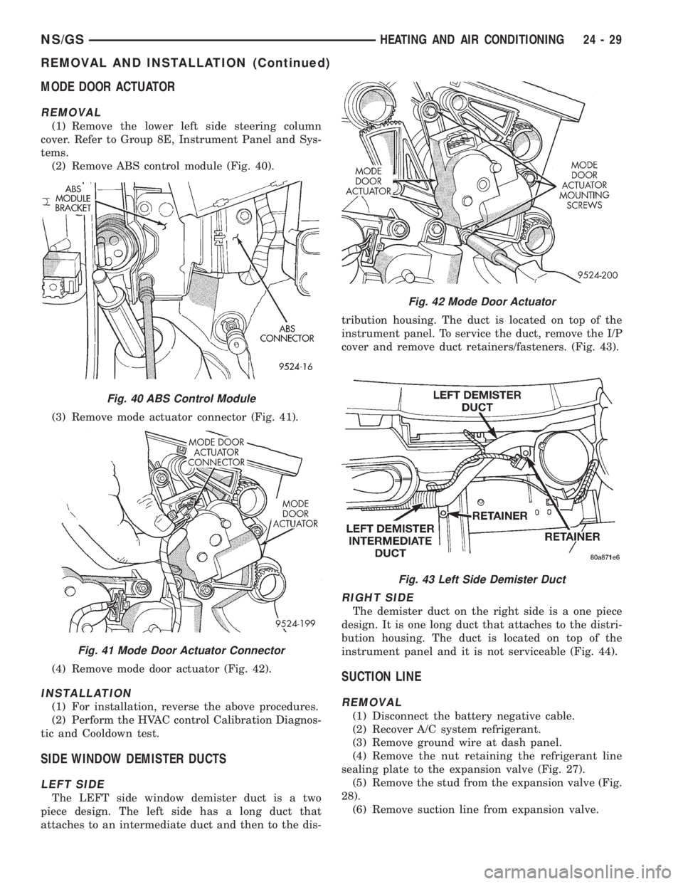
(2) Remove ABS control module (Fig. 40).
(3) Remove mode actuator connector (Fig. 41).
(4) Remove mode door actuator (Fig. 42).
INSTALLATION
(1) For installation, reverse the above procedures.
(2) Perform the HVAC control Calibration Diagnos-
tic and Cooldown test.
SIDE WINDOW DEMISTER DUCTS
LEFT SIDE
The LEFT side window demister duct is a two
piece design. The left side has a long duct that
attaches to an intermediate duct and then to the dis-tribution housing. The duct is located on top of the
instrument panel. To service the duct, remove the I/P
cover and remove duct retainers/fasteners. (Fig. 43).
RIGHT SIDE
The demister duct on the right side is a one piece
design. It is one long duct that attaches to the distri-
bution housing. The duct is located on top of the
instrument panel and it is not serviceable (Fig. 44).
SUCTION LINE
REMOVAL
(1) Disconnect the battery negative cable.
(2) Recover A/C system refrigerant.
(3) Remove ground wire at dash panel.
(4) Remove the nut retaining the refrigerant line
sealing plate to the expansion valve (Fig. 27).
(5) Remove the stud from the expansion valve (Fig.
28).
(6) Remove suction line from expansion valve.
Fig. 40 ABS Control Module
Fig. 41 Mode Door Actuator Connector
Fig. 42 Mode Door Actuator
Fig. 43 Left Side Demister Duct
NS/GSHEATING AND AIR CONDITIONING 24 - 29
REMOVAL AND INSTALLATION (Continued)
Page 1913 of 1938
conditions are met, the EGR is turned off (solenoid
energized) and the O2S compensation control is mon-
itored. Turning off the EGR shifts the air fuel (A/F)
ratio in the lean direction. The O2S data should indi-
cate an increase in the O2 concentration in the com-
bustion chamber when the exhaust gases are no
longer recirculated. While this test does not directly
measure the operation of the EGR system, it can be
inferred from the shift in the O2S data whether the
EGR system is operating correctly. Because the O2S
is being used, the O2S test must pass its test before
the EGR test.
HEX 6A,6B, 6C, 6D, 6E, AE, and AFÐMISFIRE
MONITOR
Excessive engine misfire results in increased cata-
lyst temperature and causes an increase in HC emis-
sions. Severe misfires could cause catalyst damage.
To prevent catalytic convertor damage, the PCM
monitors engine misfire.
The Powertrain Control Module (PCM) monitors
for misfire during most engine operating conditions
(positive torque) by looking at changes in the crank-
shaft speed. If a misfire occurs the speed of the
crankshaft will vary more than normal.
HEX 76, 77, 78, and 79ÐFUEL SYSTEM
MONITOR
To comply with clean air regulations, vehicles are
equipped with catalytic converters. These converters
reduce the emission of hydrocarbons, oxides of nitro-
gen and carbon monoxide. The catalyst works best
when the air fuel (A/F) ratio is at or near the opti-
mum of 14.7 to 1.
The PCM is programmed to maintain the optimum
air/fuel ratio of 14.7 to 1. This is done by making
short term corrections in the fuel injector pulse width
based on the O2S output. The programmed memory
acts as a self calibration tool that the engine control-
ler uses to compensate for variations in engine spec-
ifications, sensor tolerances and engine fatigue over
the life span of the engine. By monitoring the actual
air-fuel ratio with the O2S (short term) and multiply-
ing that with the program long-term (adaptive) mem-
ory and comparing that to the limit, it can be
determined whether it will pass an emissions test. If
a malfunction occurs such that the PCM cannot
maintain the optimum A/F ratio, then the MIL will
be illuminated.
HEX 70, and B4ÐCATALYST MONITOR
To comply with clean air regulations, vehicles are
equipped with catalytic converters. These converters
reduce the emission of hydrocarbons, oxides of nitro-
gen and carbon monoxide.Normal vehicle miles or engine misfire can cause a
catalyst to decay. A meltdown of the ceramic core can
cause a reduction of the exhaust passage. This can
increase vehicle emissions and deteriorate engine
performance, driveability and fuel economy.
The catalyst monitor uses dual oxygen sensors
(O2S's) to monitor the efficiency of the converter. The
dual O2Ss strategy is based on the fact that as a cat-
alyst deteriorates, its oxygen storage capacity and its
efficiency are both reduced. By monitoring the oxy-
gen storage capacity of a catalyst, its efficiency can
be indirectly calculated. The upstream O2S is used to
detect the amount of oxygen in the exhaust gas
before the gas enters the catalytic converter. The
PCM calculates the A/F mixture from the output of
the O2S. A low voltage indicates high oxygen content
(lean mixture). A high voltage indicates a low content
of oxygen (rich mixture).
When the upstream O2S detects a lean condition,
there is an abundance of oxygen in the exhaust gas.
A functioning converter would store this oxygen so it
can use it for the oxidation of HC and CO. As the
converter absorbs the oxygen, there will be a lack of
oxygen downstream of the converter. The output of
the downstraem O2S will indicate limited activity in
this condition.
As the converter loses the ability to store oxygen,
the condition can be detected from the behavior of
the downstream O2S. When the efficiency drops, no
chemical reaction takes place. This means the con-
centration of oxygen will be the same downstream as
upstream. The output voltage of the downstream
O2S copies the voltage of the upstream sensor. The
only difference is a time lag (seen by the PCM)
between the switching of the O2S's.
To monitor the system, the number of lean-to-rich
switches of upstream and downstream O2S's is
counted. The ratio of downstream switches to
upstream switches is used to determine whether the
catalyst is operating properly. An effective catalyst
will have fewer downstream switches than it has
upstream switches i.e., a ratio closer to zero. For a
totally ineffective catalyst, this ratio will be one-to-
one, indicating that no oxidation occurs in the device.
The system must be monitored so that when cata-
lyst efficiency deteriorates and exhaust emissions
increase to over the legal limit, the MIL (check
engine lamp) will be illuminated.
HEX A0, A1, B7, and B8ÐLEAK DETECTION
PUMP MONITOR
The leak detection assembly incorporates two pri-
mary functions: it must detect a leak in the evapora-
tive system and seal the evaporative system so the
leak detection test can be run.
NSEMISSION CONTROL SYSTEMS 25 - 9
DESCRIPTION AND OPERATION (Continued)