1996 CHRYSLER VOYAGER ABS
[x] Cancel search: ABSPage 1602 of 1938
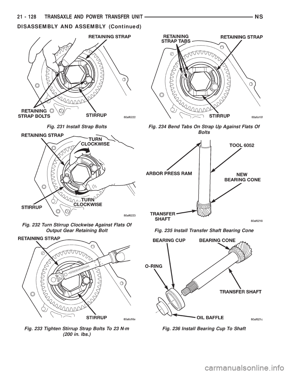
Fig. 231 Install Strap Bolts
Fig. 232 Turn Stirrup Clockwise Against Flats Of
Output Gear Retaining Bolt
Fig. 233 Tighten Stirrup Strap Bolts To 23 N´m
(200 in. lbs.)
Fig. 234 Bend Tabs On Strap Up Against Flats Of
Bolts
Fig. 235 Install Transfer Shaft Bearing Cone
Fig. 236 Install Bearing Cup To Shaft
21 - 128 TRANSAXLE AND POWER TRANSFER UNITNS
DISASSEMBLY AND ASSEMBLY (Continued)
Page 1750 of 1938
POWER SEAT SWITCH
Diagnostic information for power seat switch is
located in Group 8R, Power Seats.
REMOVAL
(1) Remove seat cushion side cover.
(2) Disconnect wire connector from power seat
switch.
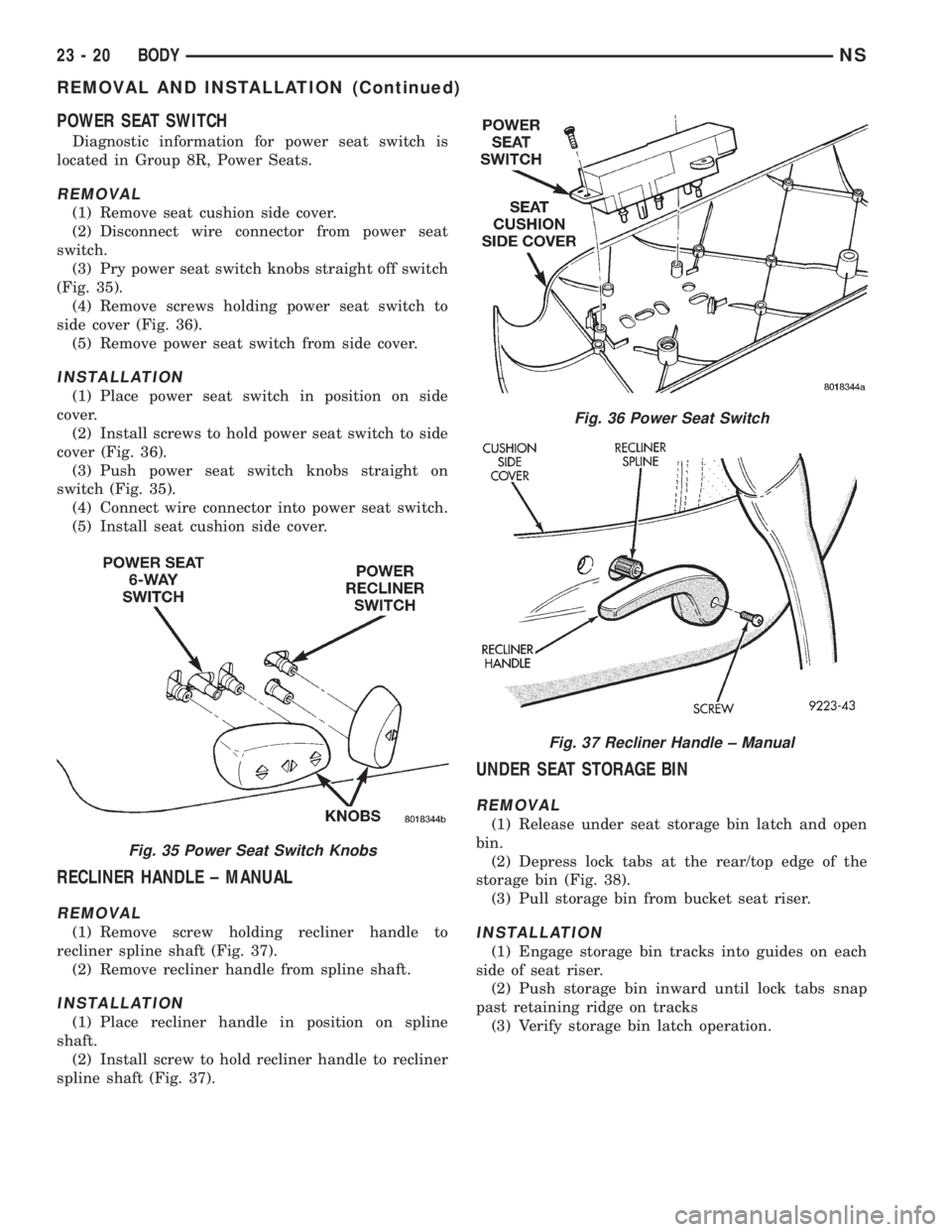
(3) Pry power seat switch knobs straight off switch
(Fig. 35).
(4) Remove screws holding power seat switch to
side cover (Fig. 36).
(5) Remove power seat switch from side cover.
INSTALLATION
(1) Place power seat switch in position on side
cover.
(2) Install screws to hold power seat switch to side
cover (Fig. 36).
(3) Push power seat switch knobs straight on
switch (Fig. 35).
(4) Connect wire connector into power seat switch.
(5) Install seat cushion side cover.
RECLINER HANDLE ± MANUAL
REMOVAL
(1) Remove screw holding recliner handle to
recliner spline shaft (Fig. 37).
(2) Remove recliner handle from spline shaft.
INSTALLATION
(1) Place recliner handle in position on spline
shaft.
(2) Install screw to hold recliner handle to recliner
spline shaft (Fig. 37).
UNDER SEAT STORAGE BIN
REMOVAL
(1) Release under seat storage bin latch and open
bin.
(2) Depress lock tabs at the rear/top edge of the
storage bin (Fig. 38).
(3) Pull storage bin from bucket seat riser.
INSTALLATION
(1) Engage storage bin tracks into guides on each
side of seat riser.
(2) Push storage bin inward until lock tabs snap
past retaining ridge on tracks
(3) Verify storage bin latch operation.
Fig. 35 Power Seat Switch Knobs
Fig. 36 Power Seat Switch
Fig. 37 Recliner Handle ± Manual
23 - 20 BODYNS
REMOVAL AND INSTALLATION (Continued)
Page 1771 of 1938
to support the hood, install bottom bolts to hold hood
to hinge finger tight.
(2) Install top bolts to hold hood to hinge finger
tight.
(3) Position bolts at marks and tighten bolts. The
hood should be aligned to 4 mm (0.160 in.) gap to the
front fenders and flush across the top surfaces along
fenders.
(4) Verify hood operation and alignment.
HOOD HINGE
REMOVAL
(1) Remove hood.
(2) Remove wiper unit. Refer to Group 8K, Wind-
shield Wipers and Washers, for procedure.
(3) Mark all bolt and hinge attachment locations
with a grease pencil or other suitable device to pro-
vide reference marks for installation.
(4) Remove bolts attaching body half of hood hinge
to front fender flange and remove hinge from vehicle
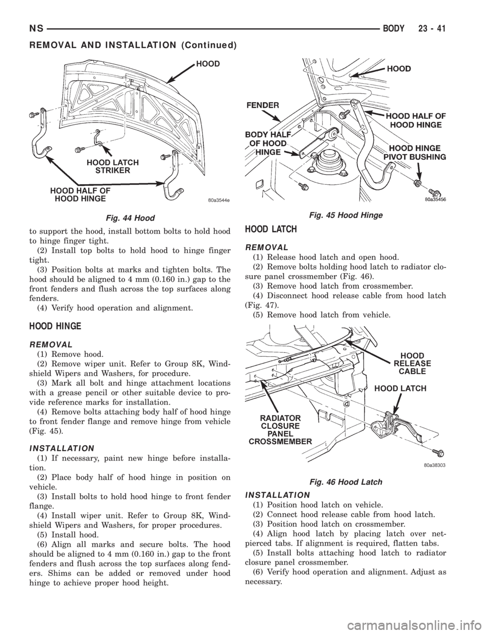
(Fig. 45).
INSTALLATION
(1) If necessary, paint new hinge before installa-
tion.
(2) Place body half of hood hinge in position on
vehicle.
(3) Install bolts to hold hood hinge to front fender
flange.
(4) Install wiper unit. Refer to Group 8K, Wind-
shield Wipers and Washers, for proper procedures.
(5) Install hood.
(6) Align all marks and secure bolts. The hood
should be aligned to 4 mm (0.160 in.) gap to the front
fenders and flush across the top surfaces along fend-
ers. Shims can be added or removed under hood
hinge to achieve proper hood height.
HOOD LATCH
REMOVAL
(1) Release hood latch and open hood.
(2) Remove bolts holding hood latch to radiator clo-
sure panel crossmember (Fig. 46).
(3) Remove hood latch from crossmember.
(4) Disconnect hood release cable from hood latch
(Fig. 47).
(5) Remove hood latch from vehicle.
INSTALLATION
(1) Position hood latch on vehicle.
(2) Connect hood release cable from hood latch.
(3) Position hood latch on crossmember.
(4) Align hood latch by placing latch over net-
pierced tabs. If alignment is required, flatten tabs.
(5) Install bolts attaching hood latch to radiator
closure panel crossmember.
(6) Verify hood operation and alignment. Adjust as
necessary.
Fig. 44 HoodFig. 45 Hood Hinge
Fig. 46 Hood Latch
NSBODY 23 - 41
REMOVAL AND INSTALLATION (Continued)
Page 1782 of 1938
INSTALLATION
(1) Place crossbar in position on roof.
(2) Engage crossbar into notch in front riser.
(3) Slide crossbar rearward into desired position.
(4) Install luggage rack front riser covers.
LUGGAGE RACK RISER COVER
REMOVAL
(1) Disengage lock tabs holding luggage rack front
riser cover to riser.
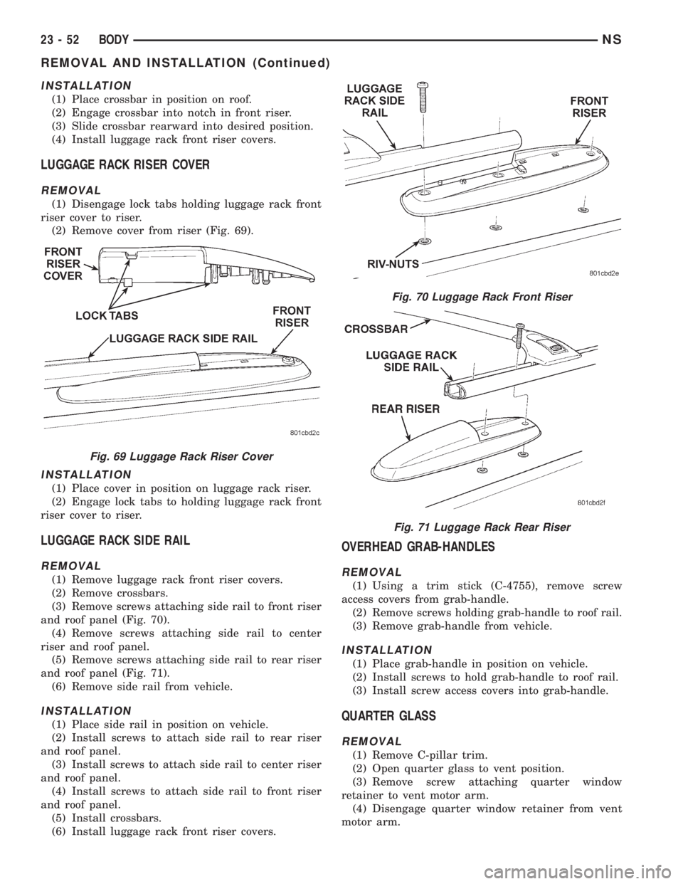
(2) Remove cover from riser (Fig. 69).
INSTALLATION
(1) Place cover in position on luggage rack riser.
(2) Engage lock tabs to holding luggage rack front
riser cover to riser.
LUGGAGE RACK SIDE RAIL
REMOVAL
(1) Remove luggage rack front riser covers.
(2) Remove crossbars.
(3) Remove screws attaching side rail to front riser
and roof panel (Fig. 70).
(4) Remove screws attaching side rail to center
riser and roof panel.
(5) Remove screws attaching side rail to rear riser
and roof panel (Fig. 71).
(6) Remove side rail from vehicle.
INSTALLATION
(1) Place side rail in position on vehicle.
(2) Install screws to attach side rail to rear riser
and roof panel.
(3) Install screws to attach side rail to center riser
and roof panel.
(4) Install screws to attach side rail to front riser
and roof panel.
(5) Install crossbars.
(6) Install luggage rack front riser covers.
OVERHEAD GRAB-HANDLES
REMOVAL
(1) Using a trim stick (C-4755), remove screw
access covers from grab-handle.
(2) Remove screws holding grab-handle to roof rail.
(3) Remove grab-handle from vehicle.
INSTALLATION
(1) Place grab-handle in position on vehicle.
(2) Install screws to hold grab-handle to roof rail.
(3) Install screw access covers into grab-handle.
QUARTER GLASS
REMOVAL
(1) Remove C-pillar trim.
(2) Open quarter glass to vent position.
(3) Remove screw attaching quarter window
retainer to vent motor arm.
(4) Disengage quarter window retainer from vent
motor arm.
Fig. 69 Luggage Rack Riser Cover
Fig. 70 Luggage Rack Front Riser
Fig. 71 Luggage Rack Rear Riser
23 - 52 BODYNS
REMOVAL AND INSTALLATION (Continued)
Page 1784 of 1938
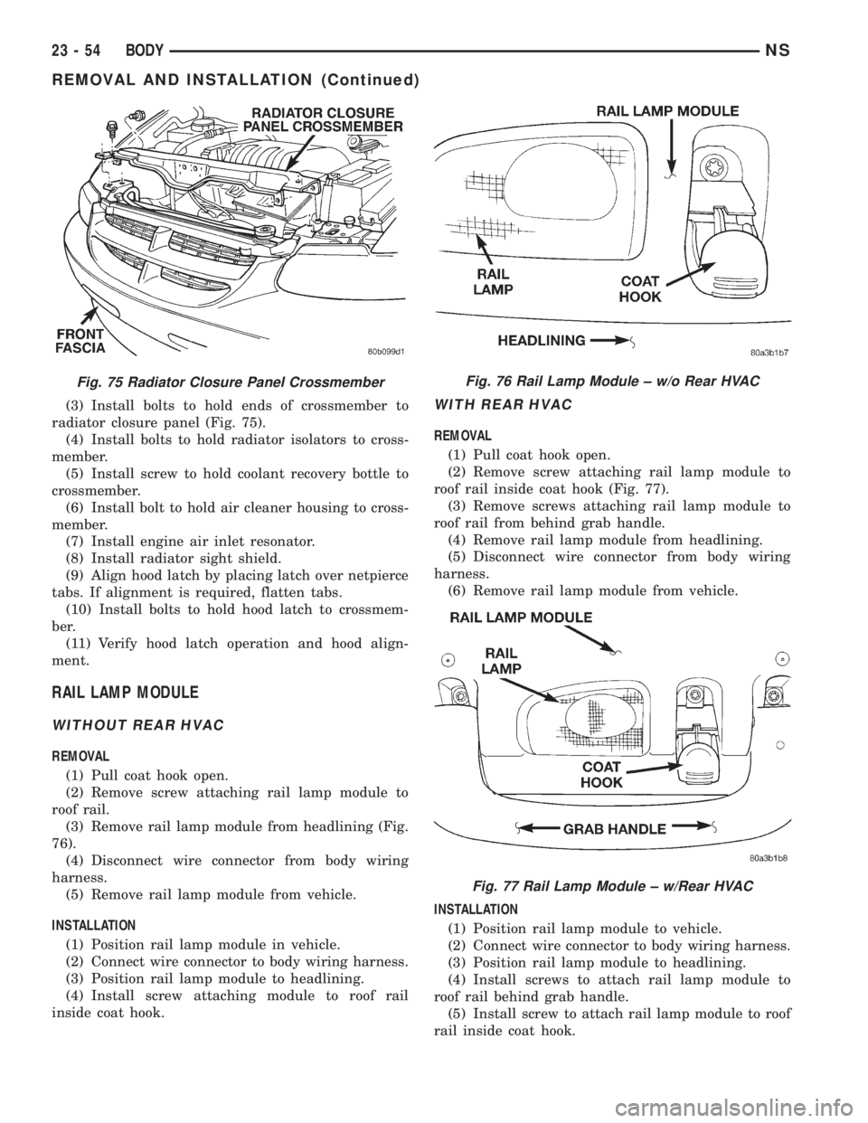
(3) Install bolts to hold ends of crossmember to
radiator closure panel (Fig. 75).
(4) Install bolts to hold radiator isolators to cross-
member.
(5) Install screw to hold coolant recovery bottle to
crossmember.
(6) Install bolt to hold air cleaner housing to cross-
member.
(7) Install engine air inlet resonator.
(8) Install radiator sight shield.
(9) Align hood latch by placing latch over netpierce
tabs. If alignment is required, flatten tabs.
(10) Install bolts to hold hood latch to crossmem-
ber.
(11) Verify hood latch operation and hood align-
ment.
RAIL LAMP MODULE
WITHOUT REAR HVAC
REMOVAL
(1) Pull coat hook open.
(2) Remove screw attaching rail lamp module to
roof rail.
(3) Remove rail lamp module from headlining (Fig.
76).
(4) Disconnect wire connector from body wiring
harness.
(5) Remove rail lamp module from vehicle.
INSTALLATION
(1) Position rail lamp module in vehicle.
(2) Connect wire connector to body wiring harness.
(3) Position rail lamp module to headlining.
(4) Install screw attaching module to roof rail
inside coat hook.
WITH REAR HVAC
REMOVAL
(1) Pull coat hook open.
(2) Remove screw attaching rail lamp module to
roof rail inside coat hook (Fig. 77).
(3) Remove screws attaching rail lamp module to
roof rail from behind grab handle.
(4) Remove rail lamp module from headlining.
(5) Disconnect wire connector from body wiring
harness.
(6) Remove rail lamp module from vehicle.
INSTALLATION
(1) Position rail lamp module to vehicle.
(2) Connect wire connector to body wiring harness.
(3) Position rail lamp module to headlining.
(4) Install screws to attach rail lamp module to
roof rail behind grab handle.
(5) Install screw to attach rail lamp module to roof
rail inside coat hook.
Fig. 75 Radiator Closure Panel CrossmemberFig. 76 Rail Lamp Module ± w/o Rear HVAC
Fig. 77 Rail Lamp Module ± w/Rear HVAC
23 - 54 BODYNS
REMOVAL AND INSTALLATION (Continued)
Page 1800 of 1938
SLIDING DOOR LATCH/LOCK CONTROL
REMOVAL
(1) Remove sliding door trim panel.
(2) Remove sliding door stop bumper.
(3) Remove sound pad, if equipped.
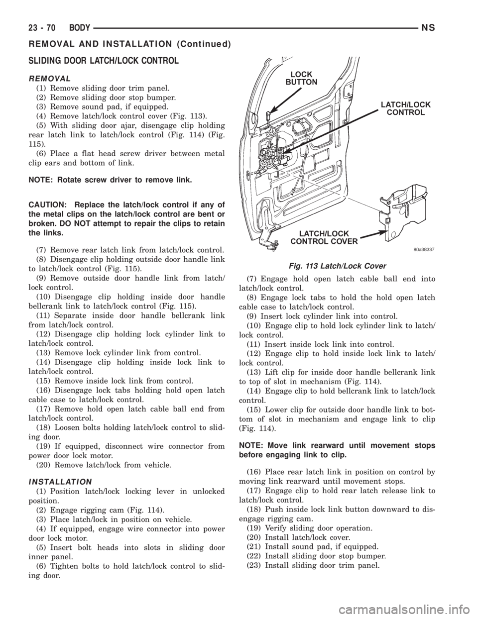
(4) Remove latch/lock control cover (Fig. 113).
(5) With sliding door ajar, disengage clip holding
rear latch link to latch/lock control (Fig. 114) (Fig.
115).
(6) Place a flat head screw driver between metal
clip ears and bottom of link.
NOTE: Rotate screw driver to remove link.
CAUTION: Replace the latch/lock control if any of
the metal clips on the latch/lock control are bent or
broken. DO NOT attempt to repair the clips to retain
the links.
(7) Remove rear latch link from latch/lock control.
(8) Disengage clip holding outside door handle link
to latch/lock control (Fig. 115).
(9) Remove outside door handle link from latch/
lock control.
(10) Disengage clip holding inside door handle
bellcrank link to latch/lock control (Fig. 115).
(11) Separate inside door handle bellcrank link
from latch/lock control.
(12) Disengage clip holding lock cylinder link to
latch/lock control.
(13) Remove lock cylinder link from control.
(14) Disengage clip holding inside lock link to
latch/lock control.
(15) Remove inside lock link from control.
(16) Disengage lock tabs holding hold open latch
cable case to latch/lock control.
(17) Remove hold open latch cable ball end from
latch/lock control.
(18) Loosen bolts holding latch/lock control to slid-
ing door.
(19) If equipped, disconnect wire connector from
power door lock motor.
(20) Remove latch/lock from vehicle.
INSTALLATION
(1) Position latch/lock locking lever in unlocked
position.
(2) Engage rigging cam (Fig. 114).
(3) Place latch/lock in position on vehicle.
(4) If equipped, engage wire connector into power
door lock motor.
(5) Insert bolt heads into slots in sliding door
inner panel.
(6) Tighten bolts to hold latch/lock control to slid-
ing door.(7) Engage hold open latch cable ball end into
latch/lock control.
(8) Engage lock tabs to hold the hold open latch
cable case to latch/lock control.
(9) Insert lock cylinder link into control.
(10) Engage clip to hold lock cylinder link to latch/
lock control.
(11) Insert inside lock link into control.
(12) Engage clip to hold inside lock link to latch/
lock control.
(13) Lift clip for inside door handle bellcrank link
to top of slot in mechanism (Fig. 114).
(14) Engage clip to hold bellcrank link to latch/lock
control.
(15) Lower clip for outside door handle link to bot-
tom of slot in mechanism and engage link to clip
(Fig. 114).
NOTE: Move link rearward until movement stops
before engaging link to clip.
(16) Place rear latch link in position on control by
moving link rearward until movement stops.
(17) Engage clip to hold rear latch release link to
latch/lock control.
(18) Push inside lock link button downward to dis-
engage rigging cam.
(19) Verify sliding door operation.
(20) Install latch/lock cover.
(21) Install sound pad, if equipped.
(22) Install sliding door stop bumper.
(23) Install sliding door trim panel.
Fig. 113 Latch/Lock Cover
23 - 70 BODYNS
REMOVAL AND INSTALLATION (Continued)
Page 1820 of 1938
absorb moisture readily out of the air. This moisture
will convert into acids within a closed system.
CAUTION: The system must be completely empty
before opening any fitting or connection in the
refrigeration system. Open fittings with caution
even after the system has been emptied. If any
pressure is noticed as a fitting is loosened,
retighten fitting and evacuate the system again.
A good rule for the flexible hose lines is to keep
the radius of all bends at least 10 times the diame-
ter of the hose. Sharper bends will reduce the flow
of refrigerant. The flexible hose lines should be
routed so they are at least 3 inches (80 mm) from
the exhaust manifold. Inspect all flexible hose lines
to make sure they are in good condition and prop-
erly routed.
The use of correct wrenches when making con-
nections is very important. Improper wrenches or
improper use of wrenches can damage the fittings.
The internal parts of the A/C system will remain
stable as long as moisture-free refrigerant and
refrigerant oil is used. Abnormal amounts of dirt,
moisture or air can upset the chemical stability.
This may cause operational troubles or even seri-
ous damage if present in more than very small
quantities.
When opening a refrigeration system, have every-
thing you will need to repair the system ready. This
will minimize the amount of time the system must
be opened. Cap or plug all lines and fittings as
soon as they are opened. This will help prevent the
entrance of dirt and moisture. All new lines and
components should be capped or sealed until they
are ready to be used.
All tools, including the refrigerant dispensing
manifold, the manifold gauge set, and test hoses
should be kept clean and dry.
HVAC CONTROL MODULE
The HVAC control module regulates the operation
of the various actuator motors. The actuator motors
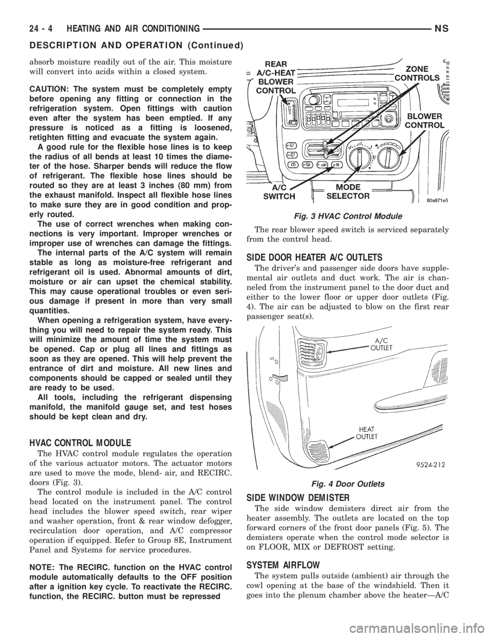
are used to move the mode, blend- air, and RECIRC.
doors (Fig. 3).
The control module is included in the A/C control
head located on the instrument panel. The control
head includes the blower speed switch, rear wiper
and washer operation, front & rear window defogger,
recirculation door operation, and A/C compressor
operation if equipped. Refer to Group 8E, Instrument
Panel and Systems for service procedures.
NOTE: The RECIRC. function on the HVAC control
module automatically defaults to the OFF position
after a ignition key cycle. To reactivate the RECIRC.
function, the RECIRC. button must be repressedThe rear blower speed switch is serviced separately
from the control head.
SIDE DOOR HEATER A/C OUTLETS
The driver's and passenger side doors have supple-
mental air outlets and duct work. The air is chan-
neled from the instrument panel to the door duct and
either to the lower floor or upper door outlets (Fig.
4). The air can be adjusted to blow on the first rear
passenger seat(s).
SIDE WINDOW DEMISTER
The side window demisters direct air from the
heater assembly. The outlets are located on the top
forward corners of the front door panels (Fig. 5). The
demisters operate when the control mode selector is
on FLOOR, MIX or DEFROST setting.
SYSTEM AIRFLOW
The system pulls outside (ambient) air through the
cowl opening at the base of the windshield. Then it
goes into the plenum chamber above the heaterÐA/C
Fig. 3 HVAC Control Module
Fig. 4 Door Outlets
24 - 4 HEATING AND AIR CONDITIONINGNS
DESCRIPTION AND OPERATION (Continued)
Page 1821 of 1938
unit housing. On air conditioned vehicles, the air
passes through the evaporator. At this point the air
flow can be directed either through or around the
heater core. This is done by adjusting the blend- air
door with the TEMP control on the control head. An
optional zone control HVAC control module is avail-
able. This unit has dual blend-air doors that can be
regulated independently of each other. The tempera-
ture setting can be different from driver's side to pas-
senger side. After the air passes the blend-air door(s),
the air flow can then be directed from the Panel,
Floor, and Defrost outlets. Air flow velocity can be
adjusted with the blower speed selector switch on the
control head.
Ambient air intake can be shut off by closing the
recirculating air door. This will recirculate the air
that is already inside the vehicle. This is done by
depressing the Recirc. button on the control head. On
air conditioned vehicles, moving the control to Mix or
Defrost depresses the A/C button and will engage the
compressor. This will send refrigerant through the
evaporator, and remove heat and humidity from the
air before it goes through the heater core.
CAUTION: In cold weather, use of the Recirculation
mode may lead to excessive window fogging. The
Recirculation mode is automatically deactivated in
Mix and Defrost modes to improve window clearing
operation.
SYSTEM OIL LEVEL
It is important to have the correct amount of oil in
the A/C system to ensure proper lubrication of the
compressor. Too little oil will result in damage to the
compressor. Too much oil will reduce the cooling
capacity of the system and consequently result in
higher discharge air temperatures.NOTE: The oil used in the compressor is ND8 PAG
R134a refrigerant oil. Only refrigerant oil of the
same type should be used to service the system.
Do not use any other oil. The oil container should
be kept tightly capped until it is ready for use.
Tightly cap afterwards to prevent contamination
from dirt and moisture. Refrigerant oil will quickly
absorb any moisture it comes in contact with. Spe-
cial effort must be used to keep all R-134a system
components moisture-free. Moisture in the oil is
very difficult to remove and will cause a reliability
problem with the compressor.
It will not be necessary to check oil level in the
compressor or to add oil unless there has been an oil
loss. Oil loss at a leak point will be evident by the
presence of a wet, shiny surface around the leak.
REFRIGERANT OIL LEVEL CHECK
When an air conditioning system is first assem-
bled, all components (except the compressor) are
refrigerant oil free. After the system has been
charged with R134a refrigerant and operated, the oil
in the compressor is dispersed through the lines and
components. The evaporator, condenser, and filter-
drier will retain a significant amount of oil, refer to
the Refrigerant Oil Capacities chart. When a compo-
nent is replaced, the specified amount of refrigerant
oil must be added. When the compressor is replaced,
the amount of oil that is retained in the rest of the
system must be drained from the replacement com-
pressor. When a line or component has ruptured and
oil has escaped, the compressor should be removed
and drained. The filter-drier must be replaced along
with the ruptured part. The oil capacity of the sys-
tem, minus the amount of oil still in the remaining
components, can be measured and poured into the
suction port of the compressor.
Example: On a dual system the evaporator retains
60 ml (2 oz). The condenser retains 30 ml (1 oz) of
oil, and system capacity may be 220 ml (7.40 oz) of
oil.
220 ml minus 90 ml = 130 ml (4.40 oz).
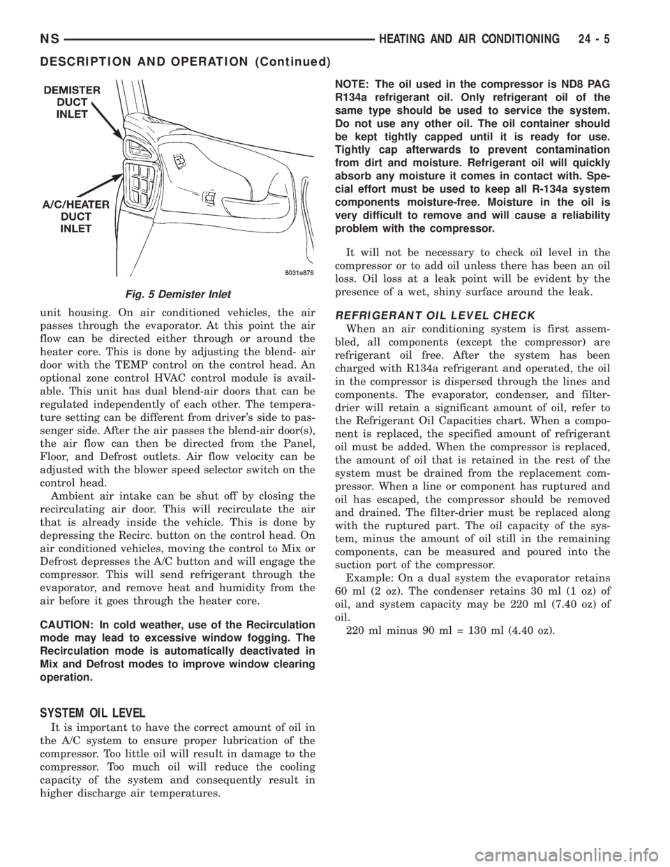
Fig. 5 Demister Inlet
NSHEATING AND AIR CONDITIONING 24 - 5
DESCRIPTION AND OPERATION (Continued)