Page 1895 of 1938

MODE DOOR ACTUATOR
REMOVAL
(1) Remove the lower left side steering column
cover. Refer to Group 8E, Instrument Panel and Sys-
tems.
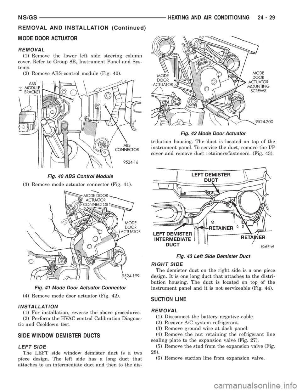
(2) Remove ABS control module (Fig. 40).
(3) Remove mode actuator connector (Fig. 41).
(4) Remove mode door actuator (Fig. 42).
INSTALLATION
(1) For installation, reverse the above procedures.
(2) Perform the HVAC control Calibration Diagnos-
tic and Cooldown test.
SIDE WINDOW DEMISTER DUCTS
LEFT SIDE
The LEFT side window demister duct is a two
piece design. The left side has a long duct that
attaches to an intermediate duct and then to the dis-tribution housing. The duct is located on top of the
instrument panel. To service the duct, remove the I/P
cover and remove duct retainers/fasteners. (Fig. 43).
RIGHT SIDE
The demister duct on the right side is a one piece
design. It is one long duct that attaches to the distri-
bution housing. The duct is located on top of the
instrument panel and it is not serviceable (Fig. 44).
SUCTION LINE
REMOVAL
(1) Disconnect the battery negative cable.
(2) Recover A/C system refrigerant.
(3) Remove ground wire at dash panel.
(4) Remove the nut retaining the refrigerant line
sealing plate to the expansion valve (Fig. 27).
(5) Remove the stud from the expansion valve (Fig.
28).
(6) Remove suction line from expansion valve.
Fig. 40 ABS Control Module
Fig. 41 Mode Door Actuator Connector
Fig. 42 Mode Door Actuator
Fig. 43 Left Side Demister Duct
NS/GSHEATING AND AIR CONDITIONING 24 - 29
REMOVAL AND INSTALLATION (Continued)
Page 1896 of 1938

(7) Remove suction line mounting nut at compres-
sor (Fig. 10).
(8) Remove suction line mounting bracket.
(9) Remove suction line.
INSTALLATION
For installation, reverse the above procedures.
²Install the stud to the evaporator sealing plate
and tighten 7 to 11 N´m (64 to 96 in. lbs.) torque.
²Install new O-rings.
²Install two-piece line in place of original part.
²Assemble line halves after it is installed on vehi-
cle.
²Evacuate and recharge A/C system.
RECIRC DOOR ACTUATOR
REMOVAL
(1) Pull back on carpeting on the right lower floor.
(2) Remove Recirc. door actuator connector.
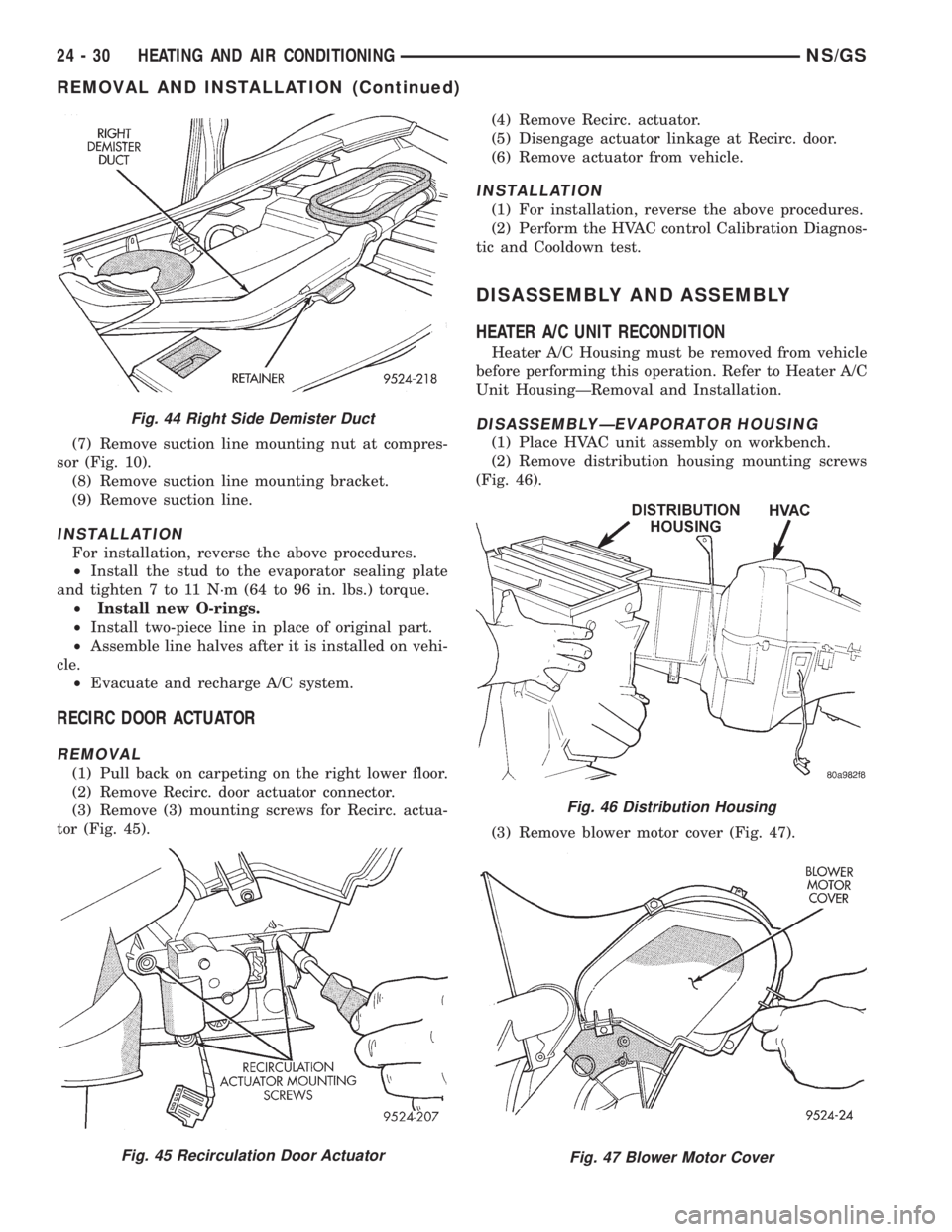
(3) Remove (3) mounting screws for Recirc. actua-
tor (Fig. 45).(4) Remove Recirc. actuator.
(5) Disengage actuator linkage at Recirc. door.
(6) Remove actuator from vehicle.
INSTALLATION
(1) For installation, reverse the above procedures.
(2) Perform the HVAC control Calibration Diagnos-
tic and Cooldown test.
DISASSEMBLY AND ASSEMBLY
HEATER A/C UNIT RECONDITION
Heater A/C Housing must be removed from vehicle
before performing this operation. Refer to Heater A/C
Unit HousingÐRemoval and Installation.
DISASSEMBLYÐEVAPORATOR HOUSING
(1) Place HVAC unit assembly on workbench.
(2) Remove distribution housing mounting screws
(Fig. 46).
(3) Remove blower motor cover (Fig. 47).
Fig. 44 Right Side Demister Duct
Fig. 45 Recirculation Door Actuator
Fig. 46 Distribution Housing
Fig. 47 Blower Motor Cover
24 - 30 HEATING AND AIR CONDITIONINGNS/GS
REMOVAL AND INSTALLATION (Continued)
Page 1897 of 1938
(4) Remove blower motor wiring grommet and feed
wiring through blower housing (Fig. 48).
(5) Remove blower motor screws. Remove blower
motor from housing (Fig. 49) and (Fig. 50).(6) Remove recirculation door cover (Fig. 51).
(7) Remove Recirc. door (Fig. 52).
(8) Remove screws around the perimeter of the
upper HVAC housing (Fig. 53).
Fig. 48 Blower Motor Grommet
Fig. 49 Blower Motor Screws
Fig. 50 Blower Motor
Fig. 51 Recirculation Door Cover
Fig. 52 Recirc. Door
Fig. 53 HVAC Cover
NS/GSHEATING AND AIR CONDITIONING 24 - 31
DISASSEMBLY AND ASSEMBLY (Continued)
Page 1898 of 1938

CAUTION: Do not damage the insulation barrier
surrounding the evaporator.
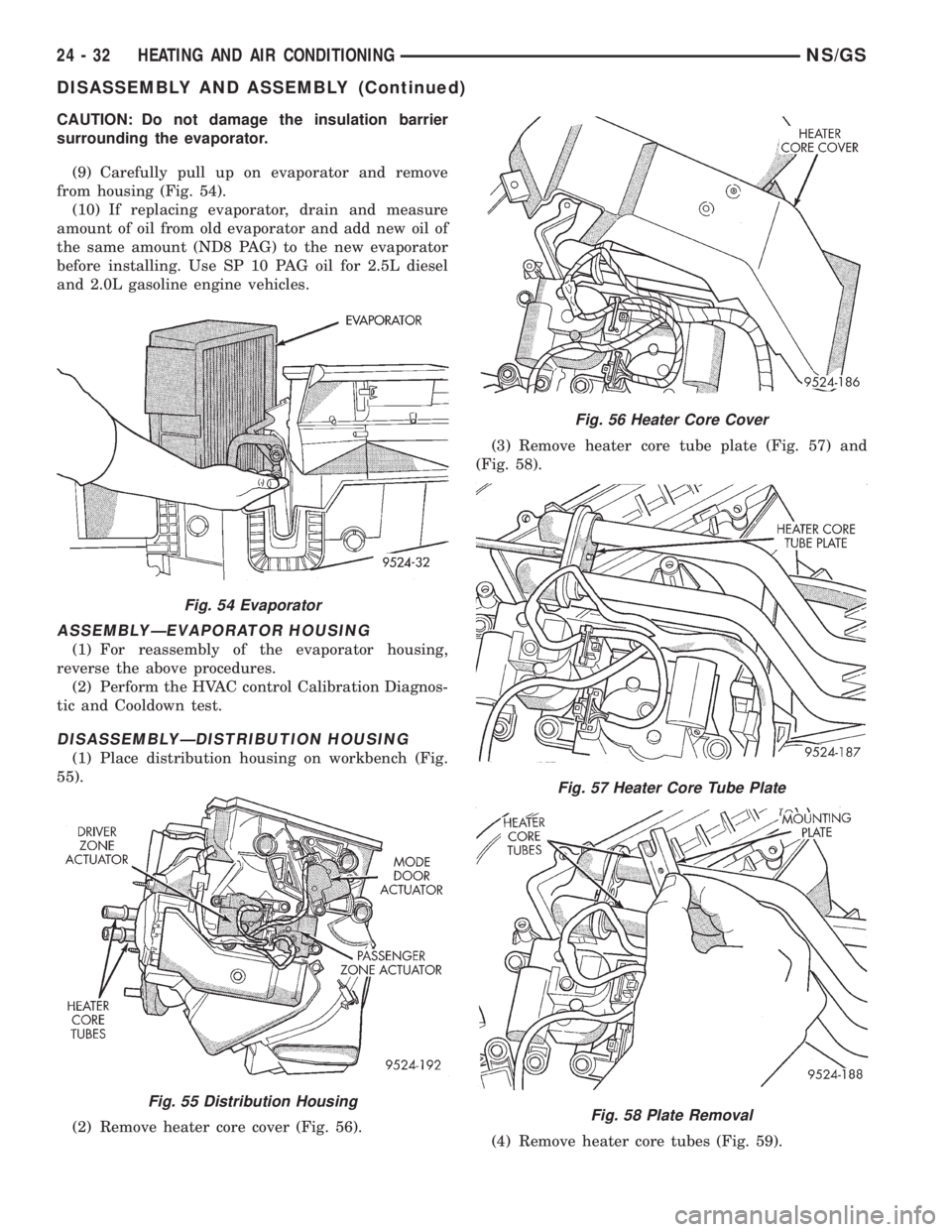
(9) Carefully pull up on evaporator and remove
from housing (Fig. 54).
(10) If replacing evaporator, drain and measure
amount of oil from old evaporator and add new oil of
the same amount (ND8 PAG) to the new evaporator
before installing. Use SP 10 PAG oil for 2.5L diesel
and 2.0L gasoline engine vehicles.
ASSEMBLYÐEVAPORATOR HOUSING
(1) For reassembly of the evaporator housing,
reverse the above procedures.
(2) Perform the HVAC control Calibration Diagnos-
tic and Cooldown test.
DISASSEMBLYÐDISTRIBUTION HOUSING
(1) Place distribution housing on workbench (Fig.
55).
(2) Remove heater core cover (Fig. 56).(3) Remove heater core tube plate (Fig. 57) and
(Fig. 58).
(4) Remove heater core tubes (Fig. 59).
Fig. 54 Evaporator
Fig. 55 Distribution Housing
Fig. 56 Heater Core Cover
Fig. 57 Heater Core Tube Plate
Fig. 58 Plate Removal
24 - 32 HEATING AND AIR CONDITIONINGNS/GS
DISASSEMBLY AND ASSEMBLY (Continued)
Page 1899 of 1938
(5) Depress heater core retaining clips at housing.
When reinstalling core use screws to fasten the
heater core to the housing.
(6) Slide heater core out of the housing.
(7) Remove driver's zone actuator from distribution
housing (Fig. 60).
(8) Remove passenger zone actuator from distribu-
tion housing (Fig. 61).
(9) Using a long thin flat blade tool, insert tool
through blend-air opening on top of distribution
housing (Fig. 62). Depress clip retaining the driver's
blend-air door drive gear. Pull out on gear and
remove from the housing (Fig. 63).
(10) Remove mode door motor.
(11) Remove Panel door actuator gear (Fig. 64).
(12) Remove defrost door actuator gear (Fig. 65).
(13) Remove cam wheel (Fig. 66).
Fig. 59 Heater Core Tube Removal
Fig. 60 Driver's Zone Actuator
Fig. 61 Passenger Zone Actuator
Fig. 62 Distribution Housing
Fig. 63 Blend-Air Door Drive Gear
NS/GSHEATING AND AIR CONDITIONING 24 - 33
DISASSEMBLY AND ASSEMBLY (Continued)
Page 1900 of 1938
(14) Remove heat door actuator gear (Fig. 67).
(15) Remove distribution housing lower cover
screws (Fig. 68).(16) Remove distribution housing half screws (Fig.
69).
(17) Remove distribution housing front cover (Fig.
70) and (Fig. 71).
Fig. 64 Panel Door Gear
Fig. 65 Defrost Door Gear
Fig. 66 Cam Wheel
Fig. 67 Heat Door Gear
Fig. 68 Distribution Housing
Fig. 69 Distribution Housing Half Screws
24 - 34 HEATING AND AIR CONDITIONINGNS/GS
DISASSEMBLY AND ASSEMBLY (Continued)
Page 1901 of 1938
(18) Remove weather-strip at fresh-air vent.
(19) Separate housing halves (Fig. 72).
(20) Pull up on separator plate and remove defrost
door (Fig. 73).
(21) Remove upper half Panel door (Fig. 74).(22) Remove upper half of Floor door (Fig. 75).
(23) Remove upper half of the blend-air door (slide
off of shaft) (Fig. 76).
Fig. 70 Front Cover
Fig. 71 View of Zone Control Doors
Fig. 72 Distribution Housing Halves
Fig. 73 Defrost Door
Fig. 74 Panel Door
Fig. 75 Floor Door
NS/GSHEATING AND AIR CONDITIONING 24 - 35
DISASSEMBLY AND ASSEMBLY (Continued)
Page 1902 of 1938
(24) Remove separator plate from distribution
housing (Fig. 77).
(25) Remove lower half of the blend-air door (Fig.
78).(26) Remove lower half of the Panel door (Fig. 79).
(27) Remove lower half of the Floor door (Fig. 80).
ASSEMBLYÐDISTRIBUTION HOUSING
For reassembly of the distribution housing, reverse
the above procedures.
To reassemble the distribution housing actuator
gears an assembly procedure of the gears and cam is
necessary.
ACTUATOR GEARS ALIGNMENT PROCEDURE
(1) Install lower FLOOR door actuator gear to
housing. Match master spline of FLOOR door actua-
tor gear to master spline on door.
(2) Install cam wheel. Align cam wheel track to
FLOOR door actuator gear.
(3) Align cam wheel slot with the post on the dis-
tribution housing marked ª1º.
Fig. 76 Blend-Air Door
Fig. 77 Separator Plate
Fig. 78 Lower Blend-Air Door
Fig. 79 Lower Panel Door
Fig. 80 Lower Floor Door
24 - 36 HEATING AND AIR CONDITIONINGNS/GS
DISASSEMBLY AND ASSEMBLY (Continued)