1996 CHRYSLER VOYAGER belt
[x] Cancel search: beltPage 1137 of 1938
CAUTION: This is a combined total dimension of
stock removal from cylinder head if any and block
top surface.
CYLINDER BORE
INSPECTION
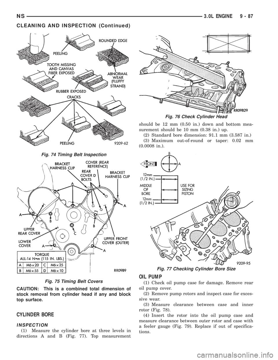
(1) Measure the cylinder bore at three levels in
directions A and B (Fig. 77). Top measurementshould be 12 mm (0.50 in.) down and bottom mea-
surement should be 10 mm (0.38 in.) up.
(2) Standard bore dimension: 91.1 mm (3.587 in.)
(3) Maximum out-of-round or taper: 0.02 mm
(0.0008 in.).
OIL PUMP
(1) Check oil pump case for damage. Remove rear
oil pump cover.
(2) Remove pump rotors and inspect case for exces-
sive wear.
(3) Measure clearance between case and inner
rotor (Fig. 78).
(4) Insert the rotor into the oil pump case and
measure clearance between outer rotor and case with
a feeler gauge (Fig. 79). Replace if out of specifica-
tions.
Fig. 74 Timing Belt Inspection
Fig. 75 Timing Belt Covers
Fig. 76 Check Cylinder Head
Fig. 77 Checking Cylinder Bore Size
NS3.0L ENGINE 9 - 87
CLEANING AND INSPECTION (Continued)
Page 1140 of 1938
Service Limit.............0.15 mm (0.006 in.)
Valve Guide
Overall Length±Intake........44mm(1.732 in.)
Overall Length±Exhaust.......48mm(1.889 in.)
Outside Diameter...........13.055 - 13.065 mm
(0.514 - 0.5143 in.)
Inside Diameter..............8.000 - 8.018 mm
(0.314 - 315 in.)
Valve Springs
Free Length (Approx.).......49.8 mm (1.960 in.)
Service Limit............48.8 mm (1.9213 in.)
Loaded Height...............40.4 mm @ 33 kg
(1.59 in. @73 lbs.)
Perpendicularity±Intake and Exhaust . . .2É (Max.)
Service Limit.....................4É(Max.)
Oil Pump
Clearance Over Rotors (Max.) .0.077 mm (0.003 in.)
Cover Out-of-Flat (Max.).....0.076 mm (0.003 in.)
Inner Rotor Thickness (Min.) .18.92 mm (0.744 in.)
Outer Rotor (Oil Pump)
Clearance (Max.)...........0.19 mm (0.007 in.)
Diameter (Min.)...........82.45 mm (3.246 in.)
Thickness (Min.)...........18.92 mm (0.744 in.)
Tip Clearance Between Rotors (Max.) . . .0.150 mm
(0.0068 in.)
Oil Pressure
At Curb Idle Speed*...........68.9 kPa (10 psi)
At 3000 rpm.........310 - 517 kPa (45 - 75 psi)
CAUTION: * If pressure is ZERO at curb Idle, DO
NOT run engine at 3,000 rpm.
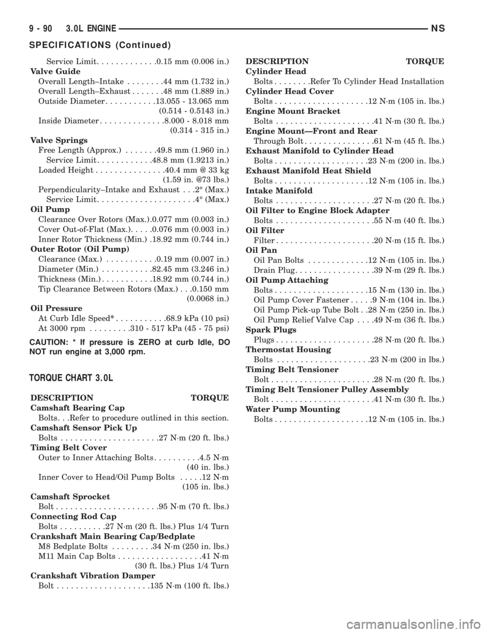
TORQUE CHART 3.0L
DESCRIPTION TORQUE
Camshaft Bearing Cap
Bolts. . .Refer to procedure outlined in this section.
Camshaft Sensor Pick Up
Bolts.....................27N´m(20ft.lbs.)
Timing Belt Cover
Outer to Inner Attaching Bolts..........4.5 N´m
(40 in. lbs.)
Inner Cover to Head/Oil Pump Bolts.....12N´m
(105 in. lbs.)
Camshaft Sprocket
Bolt......................95N´m(70ft.lbs.)
Connecting Rod Cap
Bolts..........27N´m(20ft.lbs.) Plus 1/4 Turn
Crankshaft Main Bearing Cap/Bedplate
M8 Bedplate Bolts.........34N´m(250 in. lbs.)
M11 Main Cap Bolts..................41N´m
(30 ft. lbs.) Plus 1/4 Turn
Crankshaft Vibration Damper
Bolt....................135 N´m (100 ft. lbs.)DESCRIPTION TORQUE
Cylinder Head
Bolts........Refer To Cylinder Head Installation
Cylinder Head Cover
Bolts....................12N´m(105 in. lbs.)
Engine Mount Bracket
Bolts.....................41N´m(30ft.lbs.)
Engine MountÐFront and Rear
Through Bolt...............61N´m(45ft.lbs.)
Exhaust Manifold to Cylinder Head
Bolts....................23N´m(200 in. lbs.)
Exhaust Manifold Heat Shield
Bolts....................12N´m(105 in. lbs.)
Intake Manifold
Bolts.....................27N´m(20ft.lbs.)
Oil Filter to Engine Block Adapter
Bolts.....................55N´m(40ft.lbs.)
Oil Filter
Filter.....................20N´m(15ft.lbs.)
Oil Pan
Oil Pan Bolts.............12N´m(105 in. lbs.)
Drain Plug.................39N´m(29ft.lbs.)
Oil Pump Attaching
Bolts....................15N´m(130 in. lbs.)
Oil Pump Cover Fastener.....9N´m(104 in. lbs.)
Oil Pump Pick-up Tube Bolt . .28 N´m (250 in. lbs.)
Oil Pump Relief Valve Cap. . . .49 N´m (36 ft. lbs.)
Spark Plugs
Plugs.....................28N´m(20ft.lbs.)
Thermostat Housing
Bolts....................23N´m(200 in lbs.)
Timing Belt Tensioner
Bolt......................28N´m(20ft.lbs.)
Timing Belt Tensioner Pulley Assembly
Bolt......................41N´m(30ft.lbs.)
Water Pump Mounting
Bolts....................12N´m(105 in. lbs.)
9 - 90 3.0L ENGINENS
SPECIFICATIONS (Continued)
Page 1154 of 1938
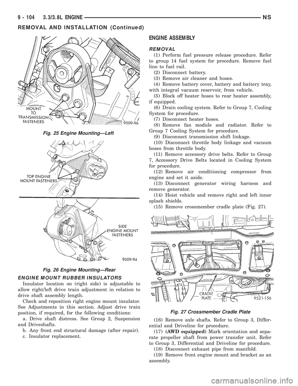
ENGINE MOUNT RUBBER INSULATORS
Insulator location on (right side) is adjustable to
allow right/left drive train adjustment in relation to
drive shaft assembly length.
Check and reposition right engine mount insulator.
See Adjustments in this section. Adjust drive train
position, if required, for the following conditions:
a. Drive shaft distress. See Group 2, Suspension
and Driveshafts.
b. Any front end structural damage (after repair).
c. Insulator replacement.
ENGINE ASSEMBLY
REMOVAL
(1) Perform fuel pressure release procedure. Refer
to group 14 fuel system for procedure. Remove fuel
line to fuel rail.
(2) Disconnect battery.
(3) Remove air cleaner and hoses.
(4) Remove battery cover, battery and battery tray,
with integral vacuum reservoir, from vehicle.
(5) Block off heater hoses to rear heater assembly,
if equipped.
(6) Drain cooling system. Refer to Group 7, Cooling
System for procedure.
(7) Disconnect heater hoses.
(8) Remove fan module and radiator. Refer to
Group 7 Cooling System for procedure.
(9) Disconnect transmission shift linkage.
(10) Disconnect throttle body linkage and vacuum
hoses from throttle body.
(11) Remove accessory drive belts. Refer to Group
7, Accessory Drive Belts located in Cooling System
for procedure.
(12) Remove air conditioning compressor from
engine and set it aside.
(13) Disconnect generator wiring harness and
remove generator.
(14) Hoist vehicle and remove right and left inner
splash shields.
(15) Remove crossmember cradle plate (Fig. 27).
(16) Remove axle shafts. Refer to Group 3, Differ-
ential and Driveline for procedure.
(17)(AWD equipped)Mark orientation and sepa-
rate propeller shaft from power transfer unit. Refer
to Group 3, Differential and Driveline for procedure.
(18) Disconnect exhaust pipe from manifold.
(19) Remove front engine mount and bracket as an
assembly.
Fig. 25 Engine MountingÐLeft
Fig. 26 Engine MountingÐRear
Fig. 27 Crossmember Cradle Plate
9 - 104 3.3/3.8L ENGINENS
REMOVAL AND INSTALLATION (Continued)
Page 1155 of 1938
(20) Remove rear transmission mount and bracket.
(21) Remove power steering pump and bracket
assembly.
(22) Remove wiring harness and connectors from
front of engine.
(23) Remove bending braces and install tool num-
ber 6912 on engine.
(24) Remove transmission inspection cover and
mark flexplate to torque converter.
(25) Remove driveplate to torque converter bolts.
(26) Lower the vehicle.
(27) Remove ground straps to body.
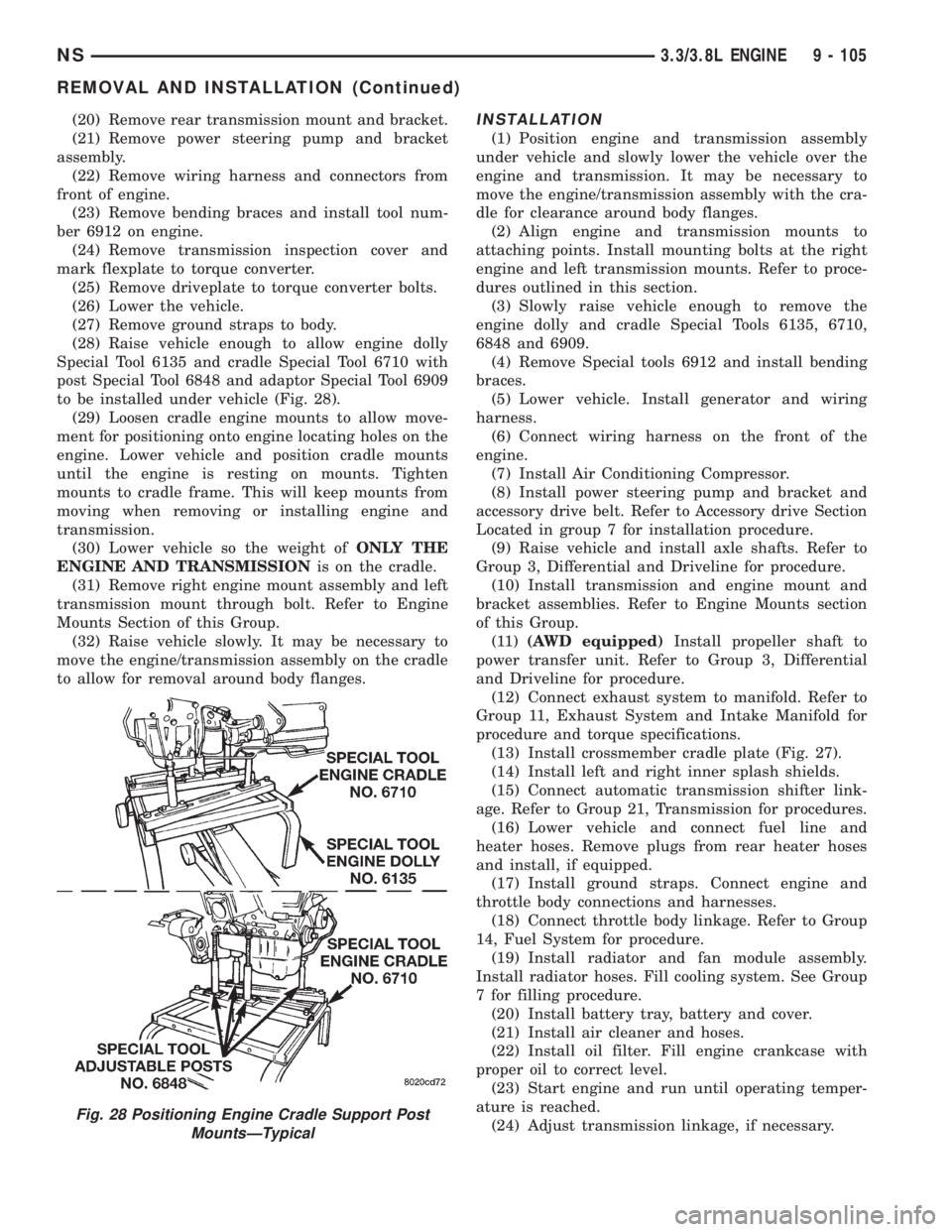
(28) Raise vehicle enough to allow engine dolly
Special Tool 6135 and cradle Special Tool 6710 with
post Special Tool 6848 and adaptor Special Tool 6909
to be installed under vehicle (Fig. 28).
(29) Loosen cradle engine mounts to allow move-
ment for positioning onto engine locating holes on the
engine. Lower vehicle and position cradle mounts
until the engine is resting on mounts. Tighten
mounts to cradle frame. This will keep mounts from
moving when removing or installing engine and
transmission.
(30) Lower vehicle so the weight ofONLY THE
ENGINE AND TRANSMISSIONis on the cradle.
(31) Remove right engine mount assembly and left
transmission mount through bolt. Refer to Engine
Mounts Section of this Group.
(32) Raise vehicle slowly. It may be necessary to
move the engine/transmission assembly on the cradle
to allow for removal around body flanges.INSTALLATION
(1) Position engine and transmission assembly
under vehicle and slowly lower the vehicle over the
engine and transmission. It may be necessary to
move the engine/transmission assembly with the cra-
dle for clearance around body flanges.
(2) Align engine and transmission mounts to
attaching points. Install mounting bolts at the right
engine and left transmission mounts. Refer to proce-
dures outlined in this section.
(3) Slowly raise vehicle enough to remove the
engine dolly and cradle Special Tools 6135, 6710,
6848 and 6909.
(4) Remove Special tools 6912 and install bending
braces.
(5) Lower vehicle. Install generator and wiring
harness.
(6) Connect wiring harness on the front of the
engine.
(7) Install Air Conditioning Compressor.
(8) Install power steering pump and bracket and
accessory drive belt. Refer to Accessory drive Section
Located in group 7 for installation procedure.
(9) Raise vehicle and install axle shafts. Refer to
Group 3, Differential and Driveline for procedure.
(10) Install transmission and engine mount and
bracket assemblies. Refer to Engine Mounts section
of this Group.
(11)(AWD equipped)Install propeller shaft to
power transfer unit. Refer to Group 3, Differential
and Driveline for procedure.
(12) Connect exhaust system to manifold. Refer to
Group 11, Exhaust System and Intake Manifold for
procedure and torque specifications.
(13) Install crossmember cradle plate (Fig. 27).
(14) Install left and right inner splash shields.
(15) Connect automatic transmission shifter link-
age. Refer to Group 21, Transmission for procedures.
(16) Lower vehicle and connect fuel line and
heater hoses. Remove plugs from rear heater hoses
and install, if equipped.
(17) Install ground straps. Connect engine and
throttle body connections and harnesses.
(18) Connect throttle body linkage. Refer to Group
14, Fuel System for procedure.
(19) Install radiator and fan module assembly.
Install radiator hoses. Fill cooling system. See Group
7 for filling procedure.
(20) Install battery tray, battery and cover.
(21) Install air cleaner and hoses.
(22) Install oil filter. Fill engine crankcase with
proper oil to correct level.
(23) Start engine and run until operating temper-
ature is reached.
(24) Adjust transmission linkage, if necessary.
Fig. 28 Positioning Engine Cradle Support Post
MountsÐTypical
NS3.3/3.8L ENGINE 9 - 105
REMOVAL AND INSTALLATION (Continued)
Page 1156 of 1938
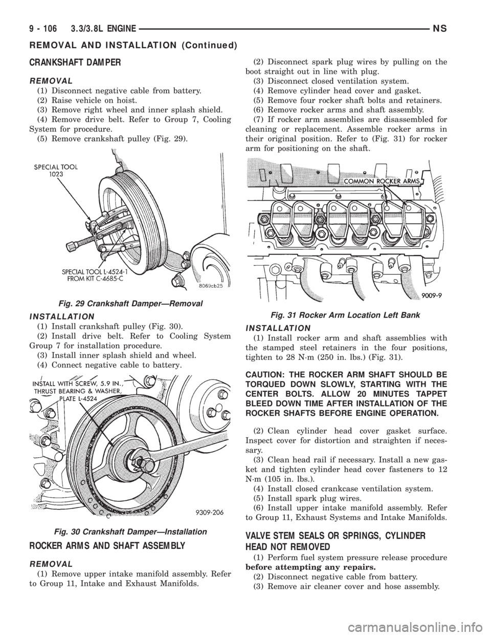
CRANKSHAFT DAMPER
REMOVAL
(1) Disconnect negative cable from battery.
(2) Raise vehicle on hoist.
(3) Remove right wheel and inner splash shield.
(4) Remove drive belt. Refer to Group 7, Cooling
System for procedure.
(5) Remove crankshaft pulley (Fig. 29).
INSTALLATION
(1) Install crankshaft pulley (Fig. 30).
(2) Install drive belt. Refer to Cooling System
Group 7 for installation procedure.
(3) Install inner splash shield and wheel.
(4) Connect negative cable to battery.
ROCKER ARMS AND SHAFT ASSEMBLY
REMOVAL
(1) Remove upper intake manifold assembly. Refer
to Group 11, Intake and Exhaust Manifolds.(2) Disconnect spark plug wires by pulling on the
boot straight out in line with plug.
(3) Disconnect closed ventilation system.
(4) Remove cylinder head cover and gasket.
(5) Remove four rocker shaft bolts and retainers.
(6) Remove rocker arms and shaft assembly.
(7) If rocker arm assemblies are disassembled for
cleaning or replacement. Assemble rocker arms in
their original position. Refer to (Fig. 31) for rocker
arm for positioning on the shaft.
INSTALLATION
(1) Install rocker arm and shaft assemblies with
the stamped steel retainers in the four positions,
tighten to 28 N´m (250 in. lbs.) (Fig. 31).
CAUTION: THE ROCKER ARM SHAFT SHOULD BE
TORQUED DOWN SLOWLY, STARTING WITH THE
CENTER BOLTS. ALLOW 20 MINUTES TAPPET
BLEED DOWN TIME AFTER INSTALLATION OF THE
ROCKER SHAFTS BEFORE ENGINE OPERATION.
(2) Clean cylinder head cover gasket surface.
Inspect cover for distortion and straighten if neces-
sary.
(3) Clean head rail if necessary. Install a new gas-
ket and tighten cylinder head cover fasteners to 12
N´m (105 in. lbs.).
(4) Install closed crankcase ventilation system.
(5) Install spark plug wires.
(6) Install upper intake manifold assembly. Refer
to Group 11, Exhaust Systems and Intake Manifolds.
VALVE STEM SEALS OR SPRINGS, CYLINDER
HEAD NOT REMOVED
(1) Perform fuel system pressure release procedure
before attempting any repairs.
(2) Disconnect negative cable from battery.
(3) Remove air cleaner cover and hose assembly.
Fig. 29 Crankshaft DamperÐRemoval
Fig. 30 Crankshaft DamperÐInstallation
Fig. 31 Rocker Arm Location Left Bank
9 - 106 3.3/3.8L ENGINENS
REMOVAL AND INSTALLATION (Continued)
Page 1161 of 1938
(6) Start and operate engine. Warm up to normal
operating temperature.
CAUTION: To prevent damage to valve mechanism,
engine must not be run above fast idle until all
hydraulic tappets have filled with oil and have
become quiet.
TIMING CHAIN COVER
REMOVAL
(1) Disconnect negative cable from battery.
(2) Drain cooling system. Refer to Cooling System
Group 7 for procedure.
(3) Support engine and remove right engine
mount.
(4) Raise vehicle on hoist. Drain engine oil.
(5) Remove oil pan and oil pump pick-up. It may
necessary to remove transaxle inspection cover.
(6) Remove right wheel and inner splash shield.
(7) Remove drive belt. Refer to Cooling System
Group 7 for procedure.
(8) Remove A/C compressor and set aside.
(9) Remove A/C compressor mounting bracket.
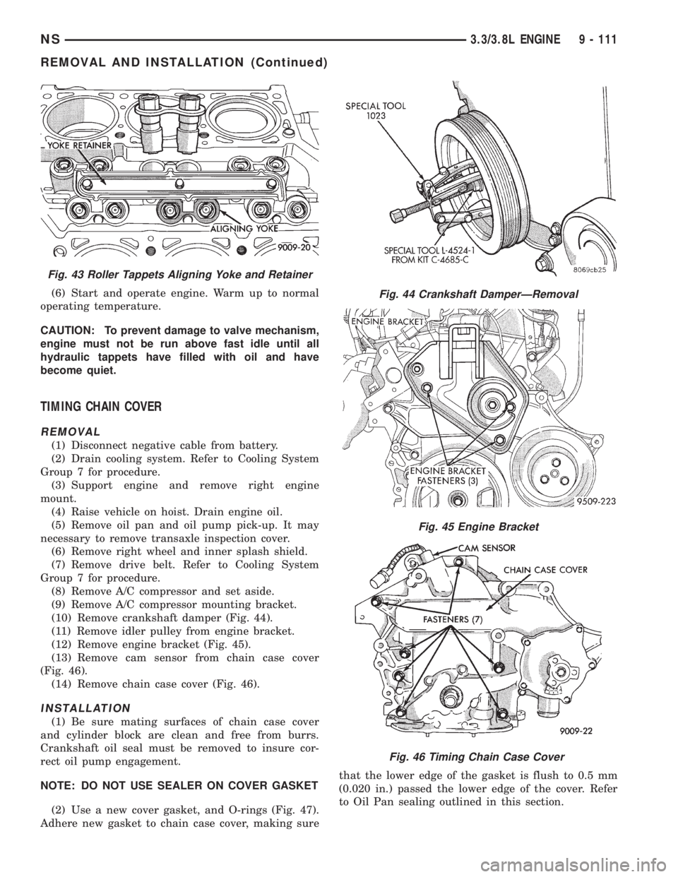
(10) Remove crankshaft damper (Fig. 44).
(11) Remove idler pulley from engine bracket.
(12) Remove engine bracket (Fig. 45).
(13) Remove cam sensor from chain case cover
(Fig. 46).
(14) Remove chain case cover (Fig. 46).
INSTALLATION
(1) Be sure mating surfaces of chain case cover
and cylinder block are clean and free from burrs.
Crankshaft oil seal must be removed to insure cor-
rect oil pump engagement.
NOTE: DO NOT USE SEALER ON COVER GASKET
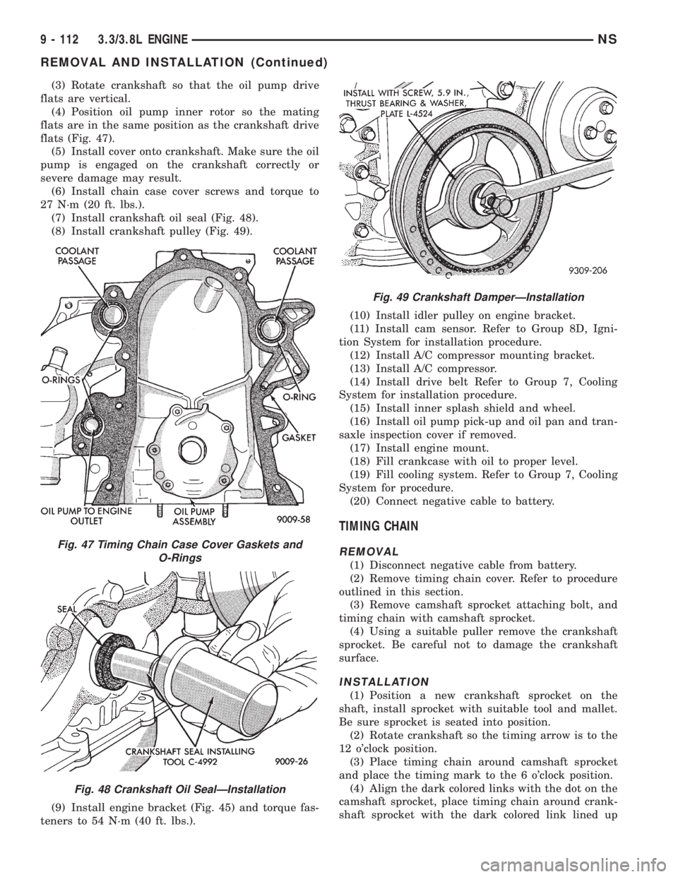
(2) Use a new cover gasket, and O-rings (Fig. 47).
Adhere new gasket to chain case cover, making surethat the lower edge of the gasket is flush to 0.5 mm
(0.020 in.) passed the lower edge of the cover. Refer
to Oil Pan sealing outlined in this section.
Fig. 43 Roller Tappets Aligning Yoke and Retainer
Fig. 44 Crankshaft DamperÐRemoval
Fig. 45 Engine Bracket
Fig. 46 Timing Chain Case Cover
NS3.3/3.8L ENGINE 9 - 111
REMOVAL AND INSTALLATION (Continued)
Page 1162 of 1938
(3) Rotate crankshaft so that the oil pump drive
flats are vertical.
(4) Position oil pump inner rotor so the mating
flats are in the same position as the crankshaft drive
flats (Fig. 47).
(5) Install cover onto crankshaft. Make sure the oil
pump is engaged on the crankshaft correctly or
severe damage may result.
(6) Install chain case cover screws and torque to
27 N´m (20 ft. lbs.).
(7) Install crankshaft oil seal (Fig. 48).
(8) Install crankshaft pulley (Fig. 49).
(9) Install engine bracket (Fig. 45) and torque fas-
teners to 54 N´m (40 ft. lbs.).(10) Install idler pulley on engine bracket.
(11) Install cam sensor. Refer to Group 8D, Igni-
tion System for installation procedure.
(12) Install A/C compressor mounting bracket.
(13) Install A/C compressor.
(14) Install drive belt Refer to Group 7, Cooling
System for installation procedure.
(15) Install inner splash shield and wheel.
(16) Install oil pump pick-up and oil pan and tran-
saxle inspection cover if removed.
(17) Install engine mount.
(18) Fill crankcase with oil to proper level.
(19) Fill cooling system. Refer to Group 7, Cooling
System for procedure.
(20) Connect negative cable to battery.
TIMING CHAIN
REMOVAL
(1) Disconnect negative cable from battery.
(2) Remove timing chain cover. Refer to procedure
outlined in this section.
(3) Remove camshaft sprocket attaching bolt, and
timing chain with camshaft sprocket.
(4) Using a suitable puller remove the crankshaft
sprocket. Be careful not to damage the crankshaft
surface.
INSTALLATION
(1) Position a new crankshaft sprocket on the
shaft, install sprocket with suitable tool and mallet.
Be sure sprocket is seated into position.
(2) Rotate crankshaft so the timing arrow is to the
12 o'clock position.
(3) Place timing chain around camshaft sprocket
and place the timing mark to the 6 o'clock position.
(4) Align the dark colored links with the dot on the
camshaft sprocket, place timing chain around crank-
shaft sprocket with the dark colored link lined up
Fig. 47 Timing Chain Case Cover Gaskets and
O-Rings
Fig. 48 Crankshaft Oil SealÐInstallation
Fig. 49 Crankshaft DamperÐInstallation
9 - 112 3.3/3.8L ENGINENS
REMOVAL AND INSTALLATION (Continued)
Page 1167 of 1938
(3) Slowly rotate crankshaft clockwise, forcing out
upper half of bearing shell.
INSTALLATION
NOTE: Only one main bearing should be selec-
tively fitted while all other main bearing caps are
properly tightened.
When installing a new upper bearing shell, slightly
chamfer the sharp edges from the plain side.
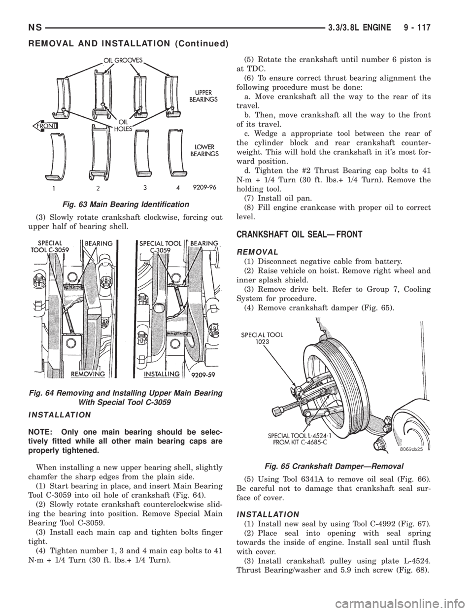
(1) Start bearing in place, and insert Main Bearing
Tool C-3059 into oil hole of crankshaft (Fig. 64).
(2) Slowly rotate crankshaft counterclockwise slid-
ing the bearing into position. Remove Special Main
Bearing Tool C-3059.
(3) Install each main cap and tighten bolts finger
tight.
(4) Tighten number 1, 3 and 4 main cap bolts to 41
N´m + 1/4 Turn (30 ft. lbs.+ 1/4 Turn).(5) Rotate the crankshaft until number 6 piston is
at TDC.
(6) To ensure correct thrust bearing alignment the
following procedure must be done:
a. Move crankshaft all the way to the rear of its
travel.
b. Then, move crankshaft all the way to the front
of its travel.
c. Wedge a appropriate tool between the rear of
the cylinder block and rear crankshaft counter-
weight. This will hold the crankshaft in it's most for-
ward position.
d. Tighten the #2 Thrust Bearing cap bolts to 41
N´m + 1/4 Turn (30 ft. lbs.+ 1/4 Turn). Remove the
holding tool.
(7) Install oil pan.
(8) Fill engine crankcase with proper oil to correct
level.
CRANKSHAFT OIL SEALÐFRONT
REMOVAL
(1) Disconnect negative cable from battery.
(2) Raise vehicle on hoist. Remove right wheel and
inner splash shield.
(3) Remove drive belt. Refer to Group 7, Cooling
System for procedure.
(4) Remove crankshaft damper (Fig. 65).
(5) Using Tool 6341A to remove oil seal (Fig. 66).
Be careful not to damage that crankshaft seal sur-
face of cover.
INSTALLATION
(1) Install new seal by using Tool C-4992 (Fig. 67).
(2) Place seal into opening with seal spring
towards the inside of engine. Install seal until flush
with cover.
(3) Install crankshaft pulley using plate L-4524.
Thrust Bearing/washer and 5.9 inch screw (Fig. 68).
Fig. 63 Main Bearing Identification
Fig. 64 Removing and Installing Upper Main Bearing
With Special Tool C-3059
Fig. 65 Crankshaft DamperÐRemoval
NS3.3/3.8L ENGINE 9 - 117
REMOVAL AND INSTALLATION (Continued)