1996 CHRYSLER VOYAGER belt
[x] Cancel search: beltPage 1197 of 1938
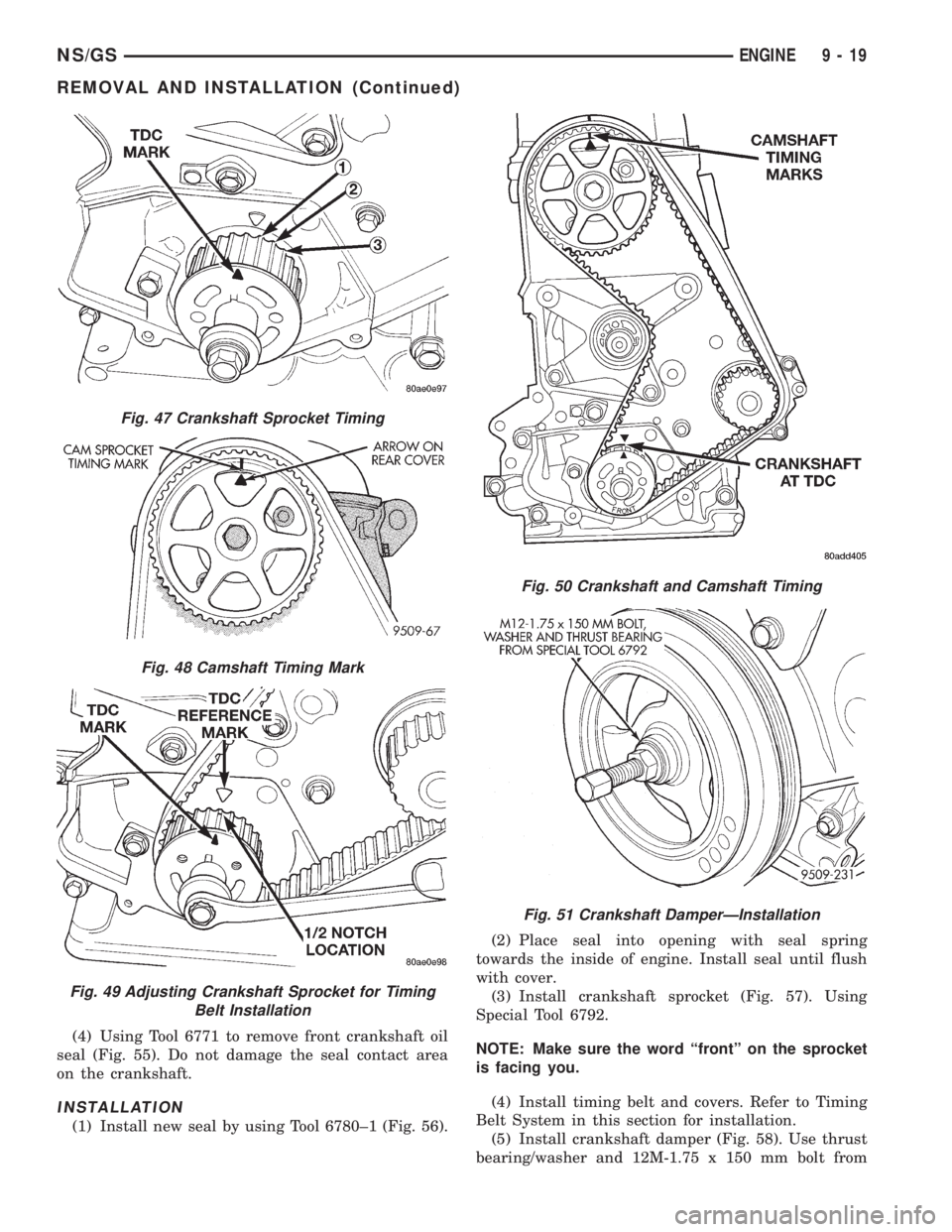
(4) Using Tool 6771 to remove front crankshaft oil
seal (Fig. 55). Do not damage the seal contact area
on the crankshaft.
INSTALLATION
(1) Install new seal by using Tool 6780±1 (Fig. 56).(2) Place seal into opening with seal spring
towards the inside of engine. Install seal until flush
with cover.
(3) Install crankshaft sprocket (Fig. 57). Using
Special Tool 6792.
NOTE: Make sure the word ªfrontº on the sprocket
is facing you.
(4) Install timing belt and covers. Refer to Timing
Belt System in this section for installation.
(5) Install crankshaft damper (Fig. 58). Use thrust
bearing/washer and 12M-1.75 x 150 mm bolt from
Fig. 47 Crankshaft Sprocket Timing
Fig. 48 Camshaft Timing Mark
Fig. 49 Adjusting Crankshaft Sprocket for Timing
Belt Installation
Fig. 50 Crankshaft and Camshaft Timing
Fig. 51 Crankshaft DamperÐInstallation
NS/GSENGINE 9 - 19
REMOVAL AND INSTALLATION (Continued)
Page 1203 of 1938
filter on until gasket contacts base. Tighten to 21
N´m (15 ft. lbs.).
OIL PUMP
REMOVAL
(1) Disconnect negative cable from battery.
(2) Remove Timing Belt. Refer to Timing Belt Sys-
tem, in this section.
(3) Remove Oil Pan. Refer to Oil Pan Removal in
this section.
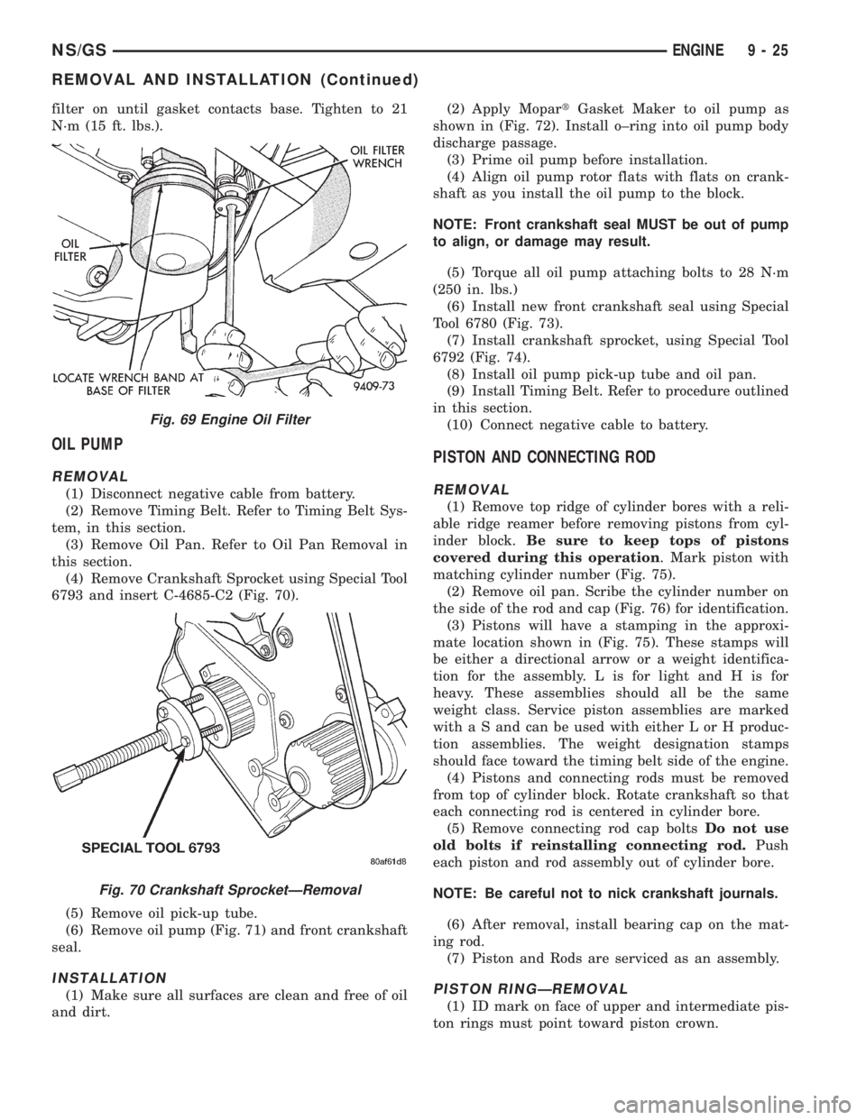
(4) Remove Crankshaft Sprocket using Special Tool
6793 and insert C-4685-C2 (Fig. 70).
(5) Remove oil pick-up tube.
(6) Remove oil pump (Fig. 71) and front crankshaft
seal.
INSTALLATION
(1) Make sure all surfaces are clean and free of oil
and dirt.(2) Apply MopartGasket Maker to oil pump as
shown in (Fig. 72). Install o±ring into oil pump body
discharge passage.
(3) Prime oil pump before installation.
(4) Align oil pump rotor flats with flats on crank-
shaft as you install the oil pump to the block.
NOTE: Front crankshaft seal MUST be out of pump
to align, or damage may result.
(5) Torque all oil pump attaching bolts to 28 N´m
(250 in. lbs.)
(6) Install new front crankshaft seal using Special
Tool 6780 (Fig. 73).
(7) Install crankshaft sprocket, using Special Tool
6792 (Fig. 74).
(8) Install oil pump pick-up tube and oil pan.
(9) Install Timing Belt. Refer to procedure outlined
in this section.
(10) Connect negative cable to battery.
PISTON AND CONNECTING ROD
REMOVAL
(1) Remove top ridge of cylinder bores with a reli-
able ridge reamer before removing pistons from cyl-
inder block.Be sure to keep tops of pistons
covered during this operation. Mark piston with
matching cylinder number (Fig. 75).
(2) Remove oil pan. Scribe the cylinder number on
the side of the rod and cap (Fig. 76) for identification.
(3) Pistons will have a stamping in the approxi-
mate location shown in (Fig. 75). These stamps will
be either a directional arrow or a weight identifica-
tion for the assembly. L is for light and H is for
heavy. These assemblies should all be the same
weight class. Service piston assemblies are marked
with a S and can be used with either L or H produc-
tion assemblies. The weight designation stamps
should face toward the timing belt side of the engine.
(4) Pistons and connecting rods must be removed
from top of cylinder block. Rotate crankshaft so that
each connecting rod is centered in cylinder bore.
(5) Remove connecting rod cap boltsDo not use
old bolts if reinstalling connecting rod.Push
each piston and rod assembly out of cylinder bore.
NOTE: Be careful not to nick crankshaft journals.
(6) After removal, install bearing cap on the mat-
ing rod.
(7) Piston and Rods are serviced as an assembly.
PISTON RINGÐREMOVAL
(1) ID mark on face of upper and intermediate pis-
ton rings must point toward piston crown.
Fig. 69 Engine Oil Filter
Fig. 70 Crankshaft SprocketÐRemoval
NS/GSENGINE 9 - 25
REMOVAL AND INSTALLATION (Continued)
Page 1206 of 1938
on the thrust direction. Staggering ring gap is impor-
tant for oil control.
PISTON AND ROD ÐINSTALLATION
(1) Before installing pistons and connecting rod
assemblies into the bore, be sure that compression
ring gaps are staggered so that neither is in line with
oil ring rail gap.
(2) Before installing the ring compressor, make
sure the oil ring expander ends are butted and the
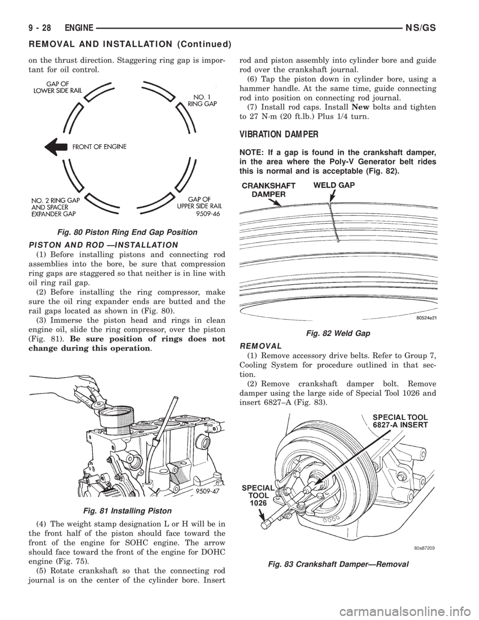
rail gaps located as shown in (Fig. 80).
(3) Immerse the piston head and rings in clean
engine oil, slide the ring compressor, over the piston
(Fig. 81).Be sure position of rings does not
change during this operation.
(4) The weight stamp designation L or H will be in
the front half of the piston should face toward the
front of the engine for SOHC engine. The arrow
should face toward the front of the engine for DOHC
engine (Fig. 75).
(5) Rotate crankshaft so that the connecting rod
journal is on the center of the cylinder bore. Insertrod and piston assembly into cylinder bore and guide
rod over the crankshaft journal.
(6) Tap the piston down in cylinder bore, using a
hammer handle. At the same time, guide connecting
rod into position on connecting rod journal.
(7) Install rod caps. InstallNewbolts and tighten
to 27 N´m (20 ft.lb.) Plus 1/4 turn.
VIBRATION DAMPER
NOTE: If a gap is found in the crankshaft damper,
in the area where the Poly-V Generator belt rides
this is normal and is acceptable (Fig. 82).
REMOVAL
(1) Remove accessory drive belts. Refer to Group 7,
Cooling System for procedure outlined in that sec-
tion.
(2) Remove crankshaft damper bolt. Remove
damper using the large side of Special Tool 1026 and
insert 6827±A (Fig. 83).
Fig. 80 Piston Ring End Gap Position
Fig. 81 Installing Piston
Fig. 82 Weld Gap
Fig. 83 Crankshaft DamperÐRemoval
9 - 28 ENGINENS/GS
REMOVAL AND INSTALLATION (Continued)
Page 1207 of 1938
INSTALLATION
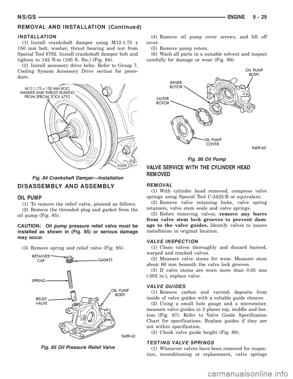
(1) Install crankshaft damper using M12-1.75 x
150 mm bolt, washer, thrust bearing and nut from
Special Tool 6792. Install crankshaft damper bolt and
tighten to 142 N´m (105 ft. lbs.) (Fig. 84).
(2) Install accessory drive belts. Refer to Group 7,
Cooling System Accessory Drive section for proce-
dure.
DISASSEMBLY AND ASSEMBLY
OIL PUMP
(1) To remove the relief valve, proceed as follows:
(2) Remove the threaded plug and gasket from the
oil pump (Fig. 85).
CAUTION: Oil pump pressure relief valve must be
installed as shown in (Fig. 85) or serious damage
may occur.
(3) Remove spring and relief valve (Fig. 85).(4) Remove oil pump cover screws, and lift off
cover.
(5) Remove pump rotors.
(6) Wash all parts in a suitable solvent and inspect
carefully for damage or wear (Fig. 86).
VALVE SERVICE WITH THE CYLINDER HEAD
REMOVED
REMOVAL
(1) With cylinder head removed, compress valve
springs using Special Tool C-3422-B or equivalent.
(2) Remove valve retaining locks, valve spring
retainers, valve stem seals and valve springs.
(3) Before removing valves,remove any burrs
from valve stem lock grooves to prevent dam-
age to the valve guides.Identify valves to insure
installation in original location.
VALVE INSPECTION
(1) Clean valves thoroughly and discard burned,
warped and cracked valves.
(2) Measure valve stems for wear. Measure stem
about 60 mm beneath the valve lock grooves.
(3) If valve stems are worn more than 0.05 mm
(.002 in.), replace valve.
VALVE GUIDES
(1) Remove carbon and varnish deposits from
inside of valve guides with a reliable guide cleaner.
(2) Using a small hole gauge and a micrometer,
measure valve guides in 3 places top, middle and bot-
tom (Fig. 87). Refer to Valve Guide Specification
Chart for specifications. Replace guides if they are
not within specification.
(3) Check valve guide height (Fig. 88).
TESTING VALVE SPRINGS
(1) Whenever valves have been removed for inspec-
tion, reconditioning or replacement, valve springs
Fig. 84 Crankshaft DamperÐInstallation
Fig. 85 Oil Pressure Relief Valve
Fig. 86 Oil Pump
NS/GSENGINE 9 - 29
REMOVAL AND INSTALLATION (Continued)
Page 1214 of 1938
Valve Margin
Intake.....1.15 ± 1.48 mm (0.0452 ± 0.0582 in.)
Exhaust....1.475 ± 1.805 mm (0.058 ± 0.071 in.)
Valve Length (Overall)
Intake....114.69 ± 115.19 mm (4.515 ± 4.535 in.)
Exhaust . . 109.59 ± 110.09 mm (4.603 ± 4.623 in.)
Valve Stem Tip Height
Intake.......45.01 ± 46.07 mm (1.77 ± 1.81 in.)
Exhaust......43.51 ± 44.57 mm (1.71 ± 1.75 in.)
Stem Diameter
Intake.....5.934 ± 5.952 mm (0.234 ± 0.234 in.)
Exhaust....5.906 ± 5.924 mm (0.233 ± 0.233 in.)
Stem to Guide Clearance
Intake . . . 0.048 ± 0.066 mm (0.0018 ± 0.0025 in.)
Exhaust . 0.0736 ± 0.094 mm (0.0029 ± 0.0037 in.)
Max. Allowable Intake.....0.076 mm (0.003 in.)
Max. Allowable Exhaust....0.101 mm (0.004 in.)
Valve Springs
Free Length (Approx.)......44.4 mm (1.747 in.)
Nominal Force (Valve closed) . 91 N´m @ 39.8 mm
(67 ft. lbs. @ 1.57 in.)
Nominal Force (Valve open) . 239 N´m @ 32.6 mm
(176 lbs. @ 1.28 in.)
Installed Height..........40.18 mm (1.580 in.)
* SERVICE AS AN ASSEMBLY WITH ROCKER
ARM.
** ALL READINGS IN CRANKSHAFT DEGREES,
AT 0.5 mm (0.019 in.) OF VALVE LIFT.
TORQUE CHART 2.0L SOHC
DESCRIPTION...................TORQUE
Camshaft Sensor Pick Up
Bolts...................9.6N´m(85in.lbs.)
Camshaft Sprocket
Bolt....................115N´m(85ft.lbs.)
Connecting Rod Cap
Bolts.........27N´m(20ft.lbs.) Plus 1/4 Turn
CollarÐOil Pan to Transaxle
Step 1: Collar to Oil Pan Bolts . 3 N´m (30 in. lbs.)
Step 2: Collar to Transaxle
Bolts...................108N´m(80ft.lbs.)
Step 3: Collar to Oil Pan
Bolts....................54N´m(40ft.lbs.)
Crankshaft Main Bearing Cap/Bedplate
M8 Bedplate Bolts..........30N´m(22ft.lbs.)
M11 Main Cap Bolts........81N´m(60ft.lbs.)
Crankshaft Damper
Bolt...................142N´m(105 ft. lbs.)
Cylinder Head
Bolts.......Refer To Cylinder Head Installation
Cylinder Head Cover
Bolts...................12N´m(105 in. lbs.)
Engine Mount BracketÐRight
Bolts....................61N´m(45ft.lbs.)DESCRIPTION...................TORQUE
Engine Mounting
Bolts.......Refer to Engine Mount Installation
Exhaust Manifold to Cylinder Head
Bolts...................23N´m(200 in. lbs.)
Exhaust Manifold Heat Shield
Bolts...................12N´m(105 in. lbs.)
Intake Manifold
Bolts...................12N´m(105 in. lbs.)
Oil Filter Adapter
Fastener.................80N´m(60ft.lbs.)
Oil Filter.................20N´m(15ft.lbs.)
Oil Pan
Bolts...................12N´m(105 in. lbs.)
Drain Plug...............27N´m(20ft.lbs.)
Oil Pump Attaching
Bolts...................28N´m(250 in. lbs.)
Oil Pump Cover Fastener . . . 12 N´m (105 in. lbs.)
Oil Pump Pick-up Tube Bolt . 28 N´m (250 in. lbs.)
Oil Pump Relief Valve Cap . . . 41 N´m (30 ft. lbs.)
Rocker Arm Shaft
Bolts...................28N´m(250 in. lbs.)
Spark Plugs...............28N´m(20ft.lbs.)
Thermostat Housing
Bolts...................23N´m(200 in lbs.)
Timing Belt Cover
Bolts M6................12N´m(105 in. lbs.)
Timing Belt Mechanical Tensioner Assembly
Bolts...................28N´m(250 in. lbs.)
Timing Belt Hydraulic Tensioner
Pulley Bolt...............68N´m(50ft.lbs.)
Pivot Bracket Bolt..........31N´m(23ft.lbs.)
Tensioner Bolts............31N´m(23ft.lbs.)
Water Pump Mounting
Bolts...................12N´m(105 in. lbs.)
SPECIAL TOOLS
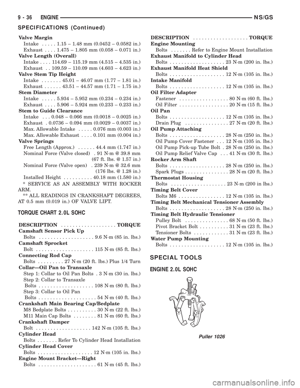
ENGINE 2.0L SOHC
Puller 1026
9 - 36 ENGINENS/GS
SPECIFICATIONS (Continued)
Page 1223 of 1938
ENGINE DIAGNOSISÐMECHANICAL CONT.
CONDITION POSSIBLE CAUSES CORRECTION
LUBRICATING OIL LOSS
(CONT.)6. Turbocharger leaking oil into the
air intake.6. Inspect air duct for evidence of oil
transfer.
7. Piston rings not sealing (oil being
consumed by the engine).7. Perform blow-by check. Repair as
required.
COMPRESSION KNOCKS 1. Air in fuel system. 1. Bleed the fuel system (refer to
Group 14, Fuel System).
2. Poor quality fuel or water/gasoline
contaminated fuel.2. Verify by operating from a
temporary tank with good fuel. Clean
and flush the fuel supply tank.
Replace fuel/water separator.
3. Engine Overloaded. 3. Verify the engine load rating is not
being exceeded.
4. Improperly operating injectors. 4. Check and replace injectors.
5. Fuel injection system defective. 5a. Instrumented injection. 5b. Timing
solenoid of the fuel pump. 5c. Pre
and post heat time of the glow plugs.
Check the fault codes in the ECU.
EXCESSIVE ENGINE NOISES 1. Drive belt squeal, insufficient
tension or abnormally high loading.1. Inspect the drive belts. Make sure
water pump pulley, generator and
power steering all turn freely.
2. Intake air and exhaust leak. 2. Refer to excessive exhaust smoke.
(Engine Diagnosis and Testing)
3. Excessive valve lash. 3. Make sure the rocker arms are not
bent. Defective hydraulic lash
adjuster.
4. Turbocharger noise. 4. Check turbocharger impeller and
turbine wheel for housing contact.
5. Power function knock. 5. Check and replace rod and main
bearings.
6. Fuel injection system defective. 6a. Instrumented injection. 6b. Timing
solenoid of the fuel pump. 6c. Pre
and post heat time of the glow plugs.
Check the fault codes in the ECU.
NS/GSENGINE 9 - 45
DIAGNOSIS AND TESTING (Continued)
Page 1232 of 1938
(28) Remove radiator support bolts.It is neces-
sary to loosen the receiver/dryer to gain access
to the radiator bolts.
(29) Remove radiator and fans as an assembly.
(30) Remove accessory drive belt generator/power
steering. Refer to Group 7, for procedure.
(31) Remove both power steering lines at pump,
and cap both lines.
NOTE: It is not necessary to discharge A/C system
for engine removal.
(32) Remove A/C compressor. Secure compressor
away from engine for clearance during engine
removal.
(33) Remove Generator and adjusting bracket.
NOTE: Do not remove the mounting base from the
generator. It is aligned at the factory and cannot be
realigned in the field.
(34) Hoist vehicle.
(35) Remove exhaust pipe at turbo outlet.
(36) Remove connections at starter.
(37) Remove power steering high pressure line
bracket at rear of oil pan.
(38) Remove both driveshafts from transaxle. Refer
to Group 2, Suspension and Driveshafts.
(39) Disconnect clutch cable at transaxle.
(40) Remove reinforcement plate on lower cross-
member.
(41) Remove front and rear engine mounts. Refer
to procedure outlined in this section.
(42) Drain engine oil and remove oil filter if neces-
sary.
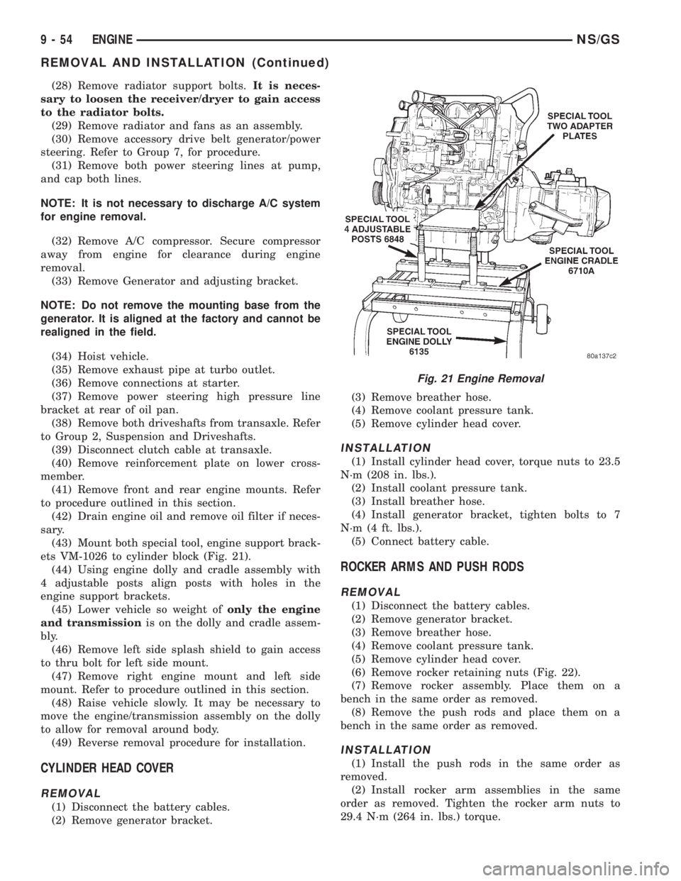
(43) Mount both special tool, engine support brack-
ets VM-1026 to cylinder block (Fig. 21).
(44) Using engine dolly and cradle assembly with
4 adjustable posts align posts with holes in the
engine support brackets.
(45) Lower vehicle so weight ofonly the engine
and transmissionis on the dolly and cradle assem-
bly.
(46) Remove left side splash shield to gain access
to thru bolt for left side mount.
(47) Remove right engine mount and left side
mount. Refer to procedure outlined in this section.
(48) Raise vehicle slowly. It may be necessary to
move the engine/transmission assembly on the dolly
to allow for removal around body.
(49) Reverse removal procedure for installation.
CYLINDER HEAD COVER
REMOVAL
(1) Disconnect the battery cables.
(2) Remove generator bracket.(3) Remove breather hose.
(4) Remove coolant pressure tank.
(5) Remove cylinder head cover.
INSTALLATION
(1) Install cylinder head cover, torque nuts to 23.5
N´m (208 in. lbs.).
(2) Install coolant pressure tank.
(3) Install breather hose.
(4) Install generator bracket, tighten bolts to 7
N´m (4 ft. lbs.).
(5) Connect battery cable.
ROCKER ARMS AND PUSH RODS
REMOVAL
(1) Disconnect the battery cables.
(2) Remove generator bracket.
(3) Remove breather hose.
(4) Remove coolant pressure tank.
(5) Remove cylinder head cover.
(6) Remove rocker retaining nuts (Fig. 22).
(7) Remove rocker assembly. Place them on a
bench in the same order as removed.
(8) Remove the push rods and place them on a
bench in the same order as removed.
INSTALLATION
(1) Install the push rods in the same order as
removed.
(2) Install rocker arm assemblies in the same
order as removed. Tighten the rocker arm nuts to
29.4 N´m (264 in. lbs.) torque.
Fig. 21 Engine Removal
9 - 54 ENGINENS/GS
REMOVAL AND INSTALLATION (Continued)
Page 1237 of 1938
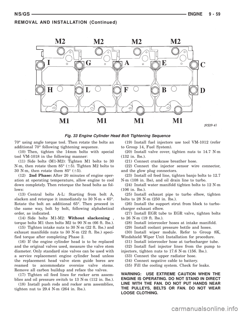
70É using angle torque tool. Then rotate the bolts an
additional 70É following tightening sequence.
(10) Then, tighten the 14mm bolts with special
tool VM-1018 in the following manner:
(11) Side bolts (M1-M2): Tighten M1 bolts to 30
N´m, then rotate them 85É (65). Tighten M2 bolts to
30 N´m, then rotate them 85É (65).
(12)2nd Phase:After 20 minutes of engine oper-
ation at operating temperature, allow engine to cool
down completely. Then retorque the head bolts as fol-
lows:
(13) Central bolts A-L: Starting from bolt A,
slacken and retorque it immediately to 30 N´m + 65É.
Rotate the bolt an additional 65É. Then proceed in
the same way, bolt by bolt, following alphabetical
order, as indicated.
(14) Side bolts M1-M2:Without slackening,
torque bolts M1 then bolts M2 to 90 N´m (66 ft. lbs.).
(15) Tighten intake nuts to 30 N´m (22 ft. lbs.) and
exhaust manifolds nuts to 30 N´m (22 ft. lbs.) speci-
fied torque after completing Phase 2.
(16) If the engine cylinder head is to be replaced
and the original valves used, measure the valve stem
diameter. Only standard size valves can be used with
a service replacement engine cylinder head unless
the replacement head valve stem guide bores are
reamed to accommodate oversize valve stems.
Remove all carbon buildup and reface the valves.
(17) Tighten oil feed lines for rocker arm assem-
blies and oil pressure switch to 13 N´m (112 in. lbs.).
(18) Install push rods and rocker arm assemblies,
tighten nut to 29.4 N´m (264 in. lbs.).(19) Install fuel injectors use tool VM-1012 (refer
to Group 14, Fuel System).
(20) Install valve cover, tighten nuts to 14.7 N´m
(132 in. lbs.).
(21) Connect crankcase breather hose.
(22) Connect the injector sensor wire connector,
and the glow plug connectors.
(23) Install oil feed line, tighten banjo bolts to 12.7
N´m (108 in. lbs), and oil drain line to turbo.
(24) Install water manifold tighten bolts to 12 N´m
(106 in. lbs.).
(25) Install exhaust pipe to turbo elbow, tighten
bolts to 28 N´m (250 in. lbs.).
(26) Install the support strut from block to turbo-
charger exhaust elbow.
(27) Install EGR tube to EGR valve, tighten bolts
to 26 N´m (19 ft. lbs.).
(28) Install intercooler hoses at intake manifold.
(29) Install coolant pressure bottle and hoses.
(30) Install wiper module. Refer to Group 8K,
Windshield Wiper Unit Installation for procedure.
(31) Install intercooler hose at turbocharger tube.
(32) Install fuel injector lines from the pump to
injectors, tighten nuts to 17.6 N´m (156. lbs.).
(33) Connect the upper radiator hose.
(34) Connect negative cable to battery.
(35) Fill the cooling system. Check for leaks.
WARNING: USE EXTREME CAUTION WHEN THE
ENGINE IS OPERATING. DO NOT STAND IN DIRECT
LINE WITH THE FAN. DO NOT PUT HANDS NEAR
THE PULLEYS, BELTS OR FAN. DO NOT WEAR
LOOSE CLOTHING.
Fig. 33 Engine Cylinder Head Bolt Tightening Sequence
NS/GSENGINE 9 - 59
REMOVAL AND INSTALLATION (Continued)