1996 CHRYSLER VOYAGER belt
[x] Cancel search: beltPage 1239 of 1938
(3) Install cylinder head, intake manifold, and
exhaust manifold. Refer to cylinder head installation
in this section.
(4) Install push rods in original positions.
(5) Install rocker arms in original positions.
(6) Install cylinder head cover. Refer to cylinder
valve cover installation in this section.
(7) Start and operate engine. Warm up to normal
operating temperature.
CAUTION: To prevent damage to valve mechanism,
engine must not be run above fast idle until all
hydraulic tappets have filled with oil and have
become quiet.
VIBRATION DAMPER
REMOVAL
(1) Disconnect the battery cable.
(2) Raise vehicle on hoist.
(3) Remove right side lower splash shield.
(4) Remove generator, power steering belt. Refer to
Group 7, Cooling.
(5) Remove water pump belt. Refer to Group 7,
Cooling.
(6) Remove engine starter. Refer to Group, 8B for
procedure
(7) Install flywheel locking tool VM.1014 to pre-
vent engine rotation.
NOTE: Crankshaft damper nut is left handed
thread.
(8) Remove vibration damper nut.
(9) Remove vibration damper. No special tool is
needed for removal.
CAUTION: If thread sealant is used it is important
to remove all the old thread sealant from the
threads on the crankshaft.
INSTALLATION
NOTE: Before installing damper be sure the O-ring
inside the center of the damper is in its grove.
(1) Install vibration damper.
CAUTION: Correct torque on the vibration damper
nut is important or engine damage can occur.
(2) Install vibration damper nut and tighten to 441
N´m (325 ft. lbs.).
(3) Remove flywheel locking tool, and install
engine starter.(4) Install both accessary drive belts. Refer to
Group 7, Cooling.
(5) Install right splash shield.
(6) Lower vehicle.
(7) Connect the battery cable.
TIMING GEAR COVER OIL SEAL
REMOVAL
(1) Disconnect the battery cable.
(2) Remove vibration damper. Refer to vibration
damper removal in this section.
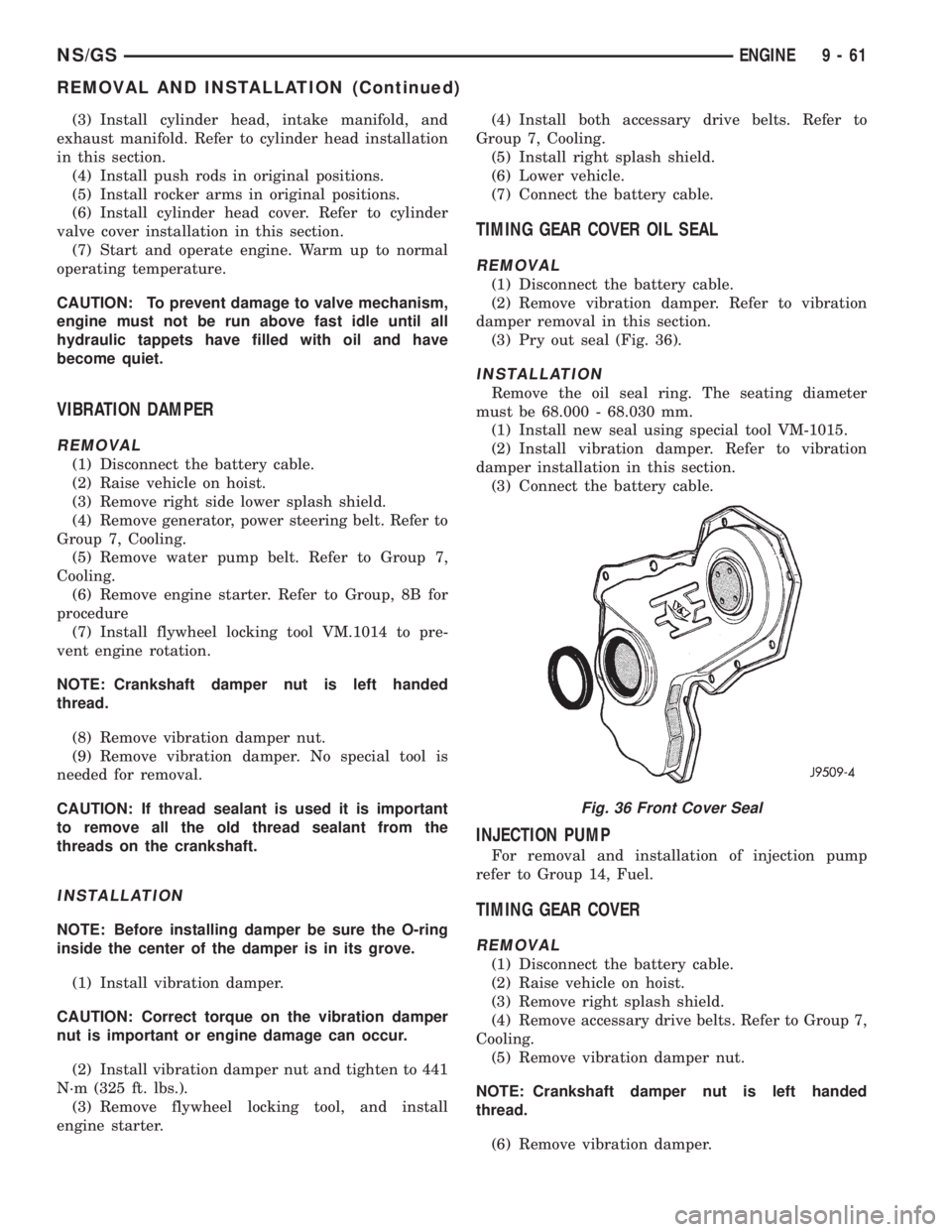
(3) Pry out seal (Fig. 36).
INSTALLATION
Remove the oil seal ring. The seating diameter
must be 68.000 - 68.030 mm.
(1) Install new seal using special tool VM-1015.
(2) Install vibration damper. Refer to vibration
damper installation in this section.
(3) Connect the battery cable.
INJECTION PUMP
For removal and installation of injection pump
refer to Group 14, Fuel.
TIMING GEAR COVER
REMOVAL
(1) Disconnect the battery cable.
(2) Raise vehicle on hoist.
(3) Remove right splash shield.
(4) Remove accessary drive belts. Refer to Group 7,
Cooling.
(5) Remove vibration damper nut.
NOTE: Crankshaft damper nut is left handed
thread.
(6) Remove vibration damper.
Fig. 36 Front Cover Seal
NS/GSENGINE 9 - 61
REMOVAL AND INSTALLATION (Continued)
Page 1240 of 1938
(7) Remove power steering/air conditioning pulley
nut. Remove pulley.
CAUTION: Remove old loctite from threads on
pump.
(8) Remove pump shaft support bracket assembly.
(9) Disconnect the water drain pipe hose at the
timing cover.
CAUTION: When separating the timing geat cover
from the block take care not to damage the mating
surface of the timing gear cover or block. Also take
care not to damage the timing gears or components
located inside the timing gear cover near the edge.
(10) Remove timing gear cover.
INSTALLATION
(1) Apply a continuous 3 mm bead of Silicone
Sealer to timing cover, install within 10 minutes,
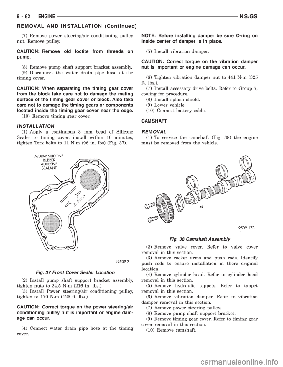
tighten Torx bolts to 11 N´m (96 in. lbs) (Fig. 37).
(2) Install pump shaft support bracket assembly,
tighten nuts to 24.5 N´m (216 in. lbs.).
(3) Install Power steering/air conditioning pulley,
tighten to 170 N´m (125 ft. lbs.).
CAUTION: Correct torque on the power steering/air
conditioning pulley nut is important or engine dam-
age can occur.
(4) Connect water drain pipe hose at the timing
cover.NOTE: Before installing damper be sure O-ring on
inside center of damper is in place.
(5) Install vibration damper.
CAUTION: Correct torque on the vibration damper
nut is important or engine damage can occur.
(6) Tighten vibration damper nut to 441 N´m (325
ft. lbs.).
(7) Install accessary drive belts. Refer to Group 7,
cooling for procedure.
(8) Install splash shield.
(9) Lower vehicle.
(10) Connect battery cable.
CAMSHAFT
REMOVAL
(1) To service the camshaft (Fig. 38) the engine
must be removed from the vehicle.
(2) Remove valve cover. Refer to valve cover
removal in this section.
(3) Remove rocker arms and push rods. Identify
push rods to ensure installation in there original
location.
(4) Remove cylinder head. Refer to cylinder head
removal in this section.
(5) Remove hydraulic tappets. Refer to tappet
removal in this section.
(6) Remove vibration damper. Refer to vibration
damper removal in this section.
(7) Remove power steering pulley.
(8) Remove pump shaft support bracket.
(9) Remove timing gear cover. Refer to timing gear
cover removal in this section.
(10) Remove camshaft.
Fig. 37 Front Cover Sealer Location
Fig. 38 Camshaft Assembly
9 - 62 ENGINENS/GS
REMOVAL AND INSTALLATION (Continued)
Page 1245 of 1938
(3) Drain oil.
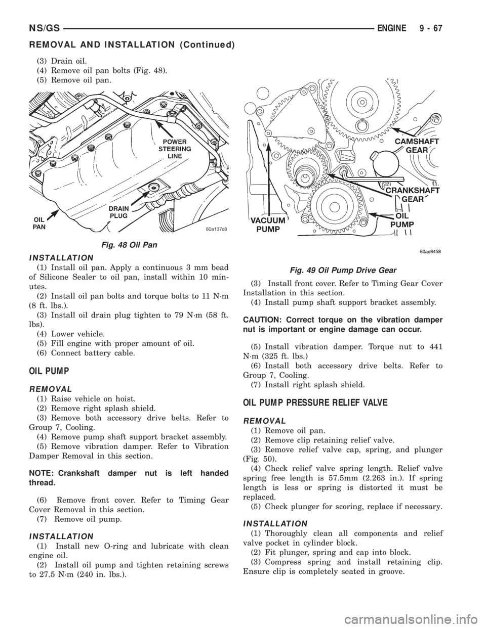
(4) Remove oil pan bolts (Fig. 48).
(5) Remove oil pan.
INSTALLATION
(1) Install oil pan. Apply a continuous 3 mm bead
of Silicone Sealer to oil pan, install within 10 min-
utes.
(2) Install oil pan bolts and torque bolts to 11 N´m
(8 ft. lbs.).
(3) Install oil drain plug tighten to 79 N´m (58 ft.
lbs).
(4) Lower vehicle.
(5) Fill engine with proper amount of oil.
(6) Connect battery cable.
OIL PUMP
REMOVAL
(1) Raise vehicle on hoist.
(2) Remove right splash shield.
(3) Remove both accessory drive belts. Refer to
Group 7, Cooling.
(4) Remove pump shaft support bracket assembly.
(5) Remove vibration damper. Refer to Vibration
Damper Removal in this section.
NOTE: Crankshaft damper nut is left handed
thread.
(6) Remove front cover. Refer to Timing Gear
Cover Removal in this section.
(7) Remove oil pump.
INSTALLATION
(1) Install new O-ring and lubricate with clean
engine oil.
(2) Install oil pump and tighten retaining screws
to 27.5 N´m (240 in. lbs.).(3) Install front cover. Refer to Timing Gear Cover
Installation in this section.
(4) Install pump shaft support bracket assembly.
CAUTION: Correct torque on the vibration damper
nut is important or engine damage can occur.
(5) Install vibration damper. Torque nut to 441
N´m (325 ft. lbs.)
(6) Install both accessory drive belts. Refer to
Group 7, Cooling.
(7) Install right splash shield.
OIL PUMP PRESSURE RELIEF VALVE
REMOVAL
(1) Remove oil pan.
(2) Remove clip retaining relief valve.
(3) Remove relief valve cap, spring, and plunger
(Fig. 50).
(4) Check relief valve spring length. Relief valve
spring free length is 57.5mm (2.263 in.). If spring
length is less or spring is distorted it must be
replaced.
(5) Check plunger for scoring, replace if necessary.
INSTALLATION
(1) Thoroughly clean all components and relief
valve pocket in cylinder block.
(2) Fit plunger, spring and cap into block.
(3) Compress spring and install retaining clip.
Ensure clip is completely seated in groove.
Fig. 48 Oil Pan
Fig. 49 Oil Pump Drive Gear
NS/GSENGINE 9 - 67
REMOVAL AND INSTALLATION (Continued)
Page 1269 of 1938
(5) Drain cooling system. Refer to Group 7, Cool-
ing System for procedure.
(6) Remove heater, and upper radiator hoses at
intake manifold.
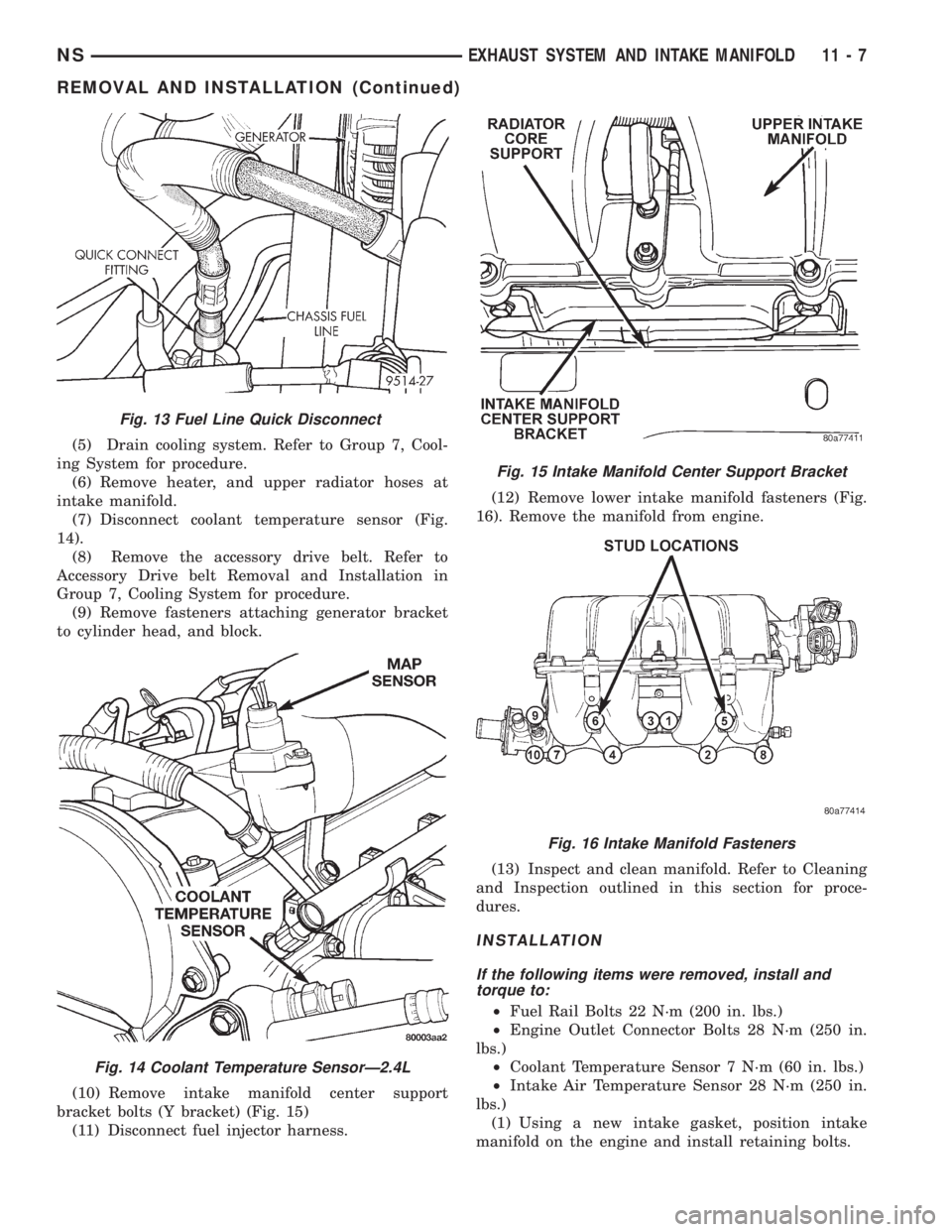
(7) Disconnect coolant temperature sensor (Fig.
14).
(8) Remove the accessory drive belt. Refer to
Accessory Drive belt Removal and Installation in
Group 7, Cooling System for procedure.
(9) Remove fasteners attaching generator bracket
to cylinder head, and block.
(10) Remove intake manifold center support
bracket bolts (Y bracket) (Fig. 15)
(11) Disconnect fuel injector harness.(12) Remove lower intake manifold fasteners (Fig.
16). Remove the manifold from engine.
(13) Inspect and clean manifold. Refer to Cleaning
and Inspection outlined in this section for proce-
dures.
INSTALLATION
If the following items were removed, install and
torque to:
²Fuel Rail Bolts 22 N´m (200 in. lbs.)
²Engine Outlet Connector Bolts 28 N´m (250 in.
lbs.)
²Coolant Temperature Sensor 7 N´m (60 in. lbs.)
²Intake Air Temperature Sensor 28 N´m (250 in.
lbs.)
(1) Using a new intake gasket, position intake
manifold on the engine and install retaining bolts.
Fig. 13 Fuel Line Quick Disconnect
Fig. 14 Coolant Temperature SensorÐ2.4L
Fig. 15 Intake Manifold Center Support Bracket
Fig. 16 Intake Manifold Fasteners
NSEXHAUST SYSTEM AND INTAKE MANIFOLD 11 - 7
REMOVAL AND INSTALLATION (Continued)
Page 1278 of 1938

CAUTION: When using the ASD Fuel System Test,
The Auto Shutdown (ASD) Relay will remain ener-
gized for 7 minutes or until the ignition switch is
turned to the OFF position, or Stop All Test is
selected.
EXHAUST MANIFOLDSÐ3.3/3.8L ENGINE
REMOVAL
(1) Disconnect battery negative cable.
(2) Remove accessory drive belt. Refer to Accessory
Drive section located in Group 7 Cooling System for
procedure.
(3) Remove generator.
(4) Raise vehicle and disconnect exhaust pipe
from rear (cowl side) exhaust manifold at flex-joint.
(5) Disconnect down stream oxygen sensor connec-
tor.
(6) Lower exhaust system to gain access to rear
manifold.
(7) Separate EGR tube from rear manifold and
disconnect Heated Oxygen Sensor lead wire (Fig. 45).
(8) Remove heat shield from rear engine mount.
(9) Remove Generator/Power Steering Support
Strut (Fig. 45).
(10) Remove bolts attaching crossover pipe to
manifold (Fig. 45).
(11) Disconnect up stream oxygen sensor connec-
tor.
(12) Remove bolts attaching rear manifold to cyl-
inder head and remove manifold.
(13) Lower vehicle and remove screws attaching
front heat shield to front manifold (Fig. 46).
(14) Remove bolts fastening crossover pipe to
front exhaust manifold and nuts fastening manifold
to cylinder head. Remove assemblies (Fig. 47).
(15) Inspect and clean manifold. Refer to Cleaning
and Inspection outlined in this section for proce-
dures.
INSTALLATION
(1) Install rear exhaust manifold and tighten
attaching bolts to 23 N´m (200 in. lbs.).
(2) Install generator.
NOTE: Inspect crossover pipe fasteners for dam-
age from heat and corrosion. Replace if necessary.
(3) Using new gasket attach crossover pipe to
exhaust manifold and tighten bolts to 54 N´m (40 ft.
lbs.) and connect oxygen sensor lead (Fig. 45).
(4) Install EGR Tube and Generator/Power Steer-
ing Strut (Fig. 45).
(5) Using new gaskets install front exhaust mani-
fold and tighten attaching bolts to 23 N´m (200 in.
lbs.).(6) Attach exhaust crossover with a new gasket
and tighten fasteners to 54 N´m (40 ft. lbs.) (Fig. 47).
(7) Connect up stream oxygen sensor connector.
(8) Install exhaust system.
Fig. 45 EGR Tube, Heated Oxygen Sensor and
Generator/Power Steering Strut
Fig. 46 Heat ShieldÐFront
Fig. 47 Crossover Pipe
11 - 16 EXHAUST SYSTEM AND INTAKE MANIFOLDNS
REMOVAL AND INSTALLATION (Continued)
Page 1279 of 1938
(9) Attach exhaust pipe to exhaust manifold using
new gasket and tighten bolts to 28 N´m (250 in. lbs.).
(10) Connect down stream oxygen sensor connec-
tor.
(11) Install front manifold heat shield and tighten
attaching screws to 12 N´m (105 in. lbs.) (Fig. 46).
(12) Install accessory drive belt. Refer to Accessory
Drive section located in Group 7 Cooling System for
procedure.
(13) Connect battery negative cable.
CLEANING AND INSPECTION
INTAKE MANIFOLD
INSPECTION
Check for:
²Damage and cracks of each section.
²Clogged water passages in end cross-overs (if
equipped).
²Check for cylinder head mounting surface distor-
tion using a straightedge and thickness gauge. Refer
to specifications for warpage specification.
CLEANING
Remove the gasket material from the manifold sur-
faces.
Be careful not to gouge or scratch the sealing sur-
face.
EXHAUST MANIFOLD
INSPECTION
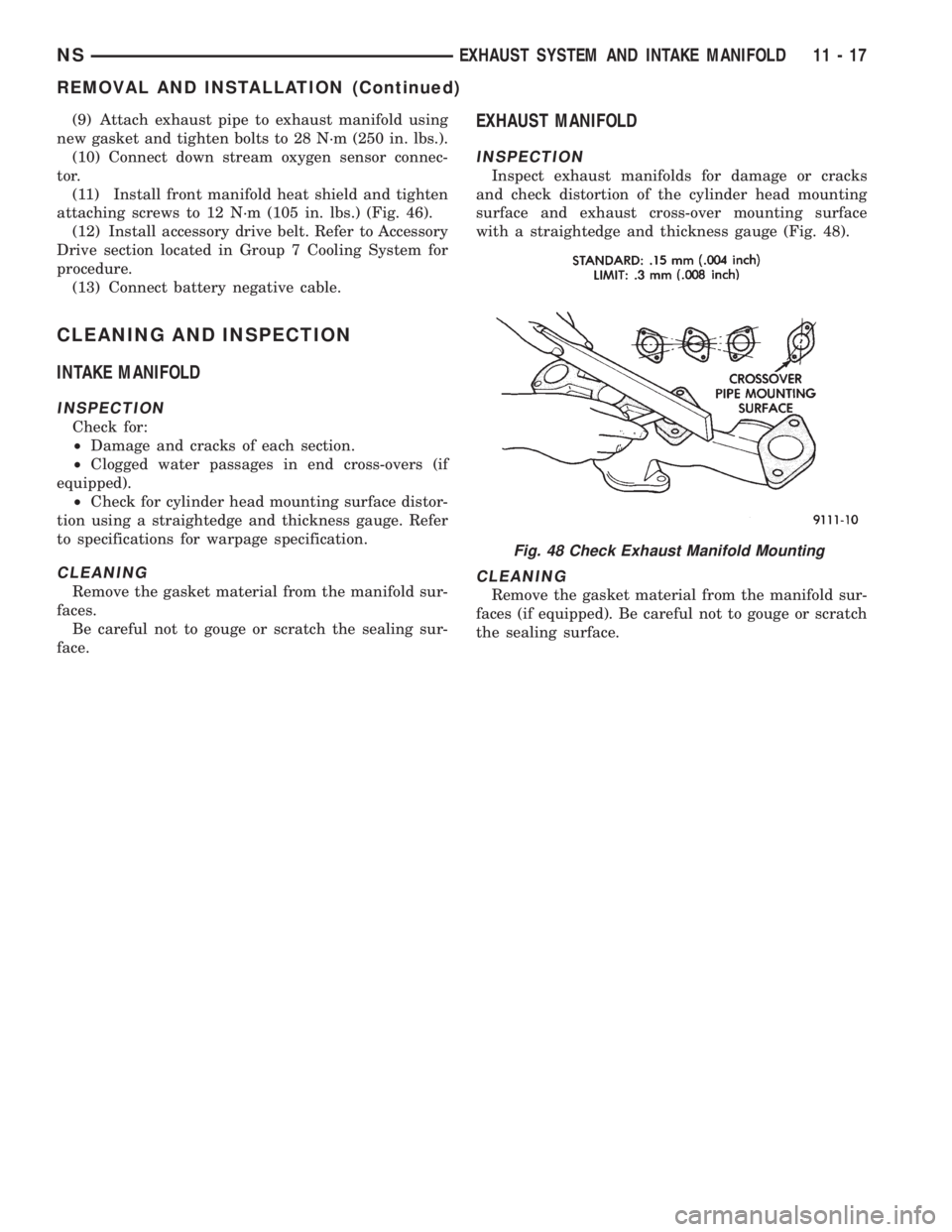
Inspect exhaust manifolds for damage or cracks
and check distortion of the cylinder head mounting
surface and exhaust cross-over mounting surface
with a straightedge and thickness gauge (Fig. 48).
CLEANING
Remove the gasket material from the manifold sur-
faces (if equipped). Be careful not to gouge or scratch
the sealing surface.
Fig. 48 Check Exhaust Manifold Mounting
NSEXHAUST SYSTEM AND INTAKE MANIFOLD 11 - 17
REMOVAL AND INSTALLATION (Continued)
Page 1345 of 1938
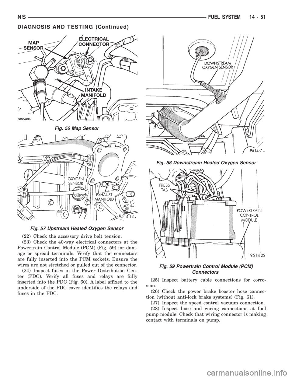
(22) Check the accessory drive belt tension.
(23) Check the 40-way electrical connectors at the
Powertrain Control Module (PCM) (Fig. 59) for dam-
age or spread terminals. Verify that the connectors
are fully inserted into the PCM sockets. Ensure the
wires are not stretched or pulled out of the connector.
(24) Inspect fuses in the Power Distribution Cen-
ter (PDC). Verify all fuses and relays are fully
inserted into the PDC (Fig. 60). A label affixed to the
underside of the PDC cover identifies the relays and
fuses in the PDC.(25) Inspect battery cable connections for corro-
sion.
(26) Check the power brake booster hose connec-
tion (without anti-lock brake systems) (Fig. 61).
(27) Inspect the speed control vacuum connection.
(28) Inspect hose and wiring connections at fuel
pump module. Check that wiring connector is making
contact with terminals on pump.
Fig. 56 Map Sensor
Fig. 57 Upstream Heated Oxygen Sensor
Fig. 58 Downstream Heated Oxygen Sensor
Fig. 59 Powertrain Control Module (PCM)
Connectors
NSFUEL SYSTEM 14 - 51
DIAGNOSIS AND TESTING (Continued)
Page 1347 of 1938
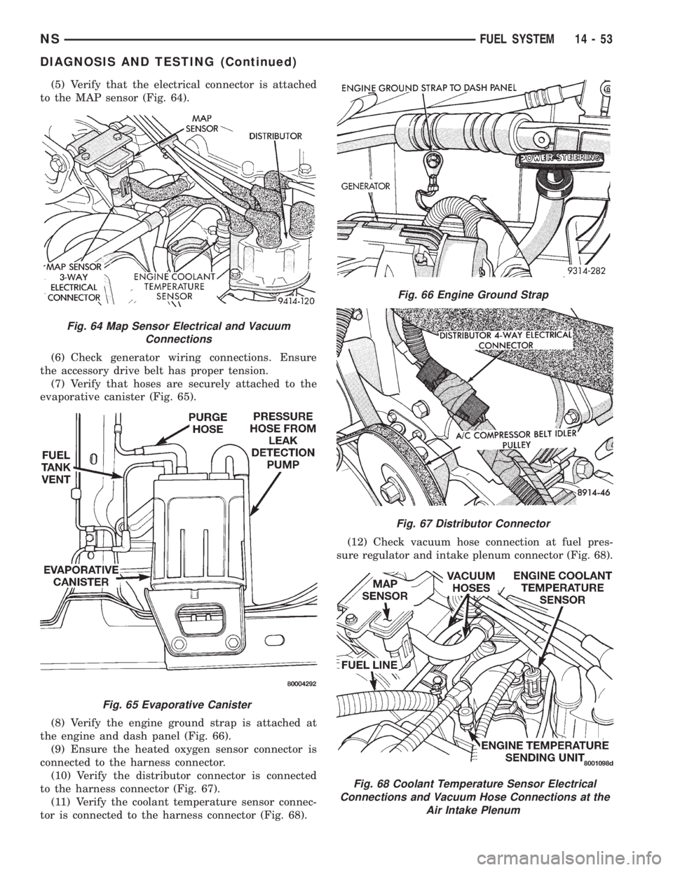
(5) Verify that the electrical connector is attached
to the MAP sensor (Fig. 64).
(6) Check generator wiring connections. Ensure
the accessory drive belt has proper tension.
(7) Verify that hoses are securely attached to the
evaporative canister (Fig. 65).
(8) Verify the engine ground strap is attached at
the engine and dash panel (Fig. 66).
(9) Ensure the heated oxygen sensor connector is
connected to the harness connector.
(10) Verify the distributor connector is connected
to the harness connector (Fig. 67).
(11) Verify the coolant temperature sensor connec-
tor is connected to the harness connector (Fig. 68).(12) Check vacuum hose connection at fuel pres-
sure regulator and intake plenum connector (Fig. 68).
Fig. 64 Map Sensor Electrical and Vacuum
Connections
Fig. 65 Evaporative Canister
Fig. 66 Engine Ground Strap
Fig. 67 Distributor Connector
Fig. 68 Coolant Temperature Sensor Electrical
Connections and Vacuum Hose Connections at the
Air Intake Plenum
NSFUEL SYSTEM 14 - 53
DIAGNOSIS AND TESTING (Continued)