1996 CHRYSLER VOYAGER suspension
[x] Cancel search: suspensionPage 1428 of 1938
DIAGNOSIS AND TESTING
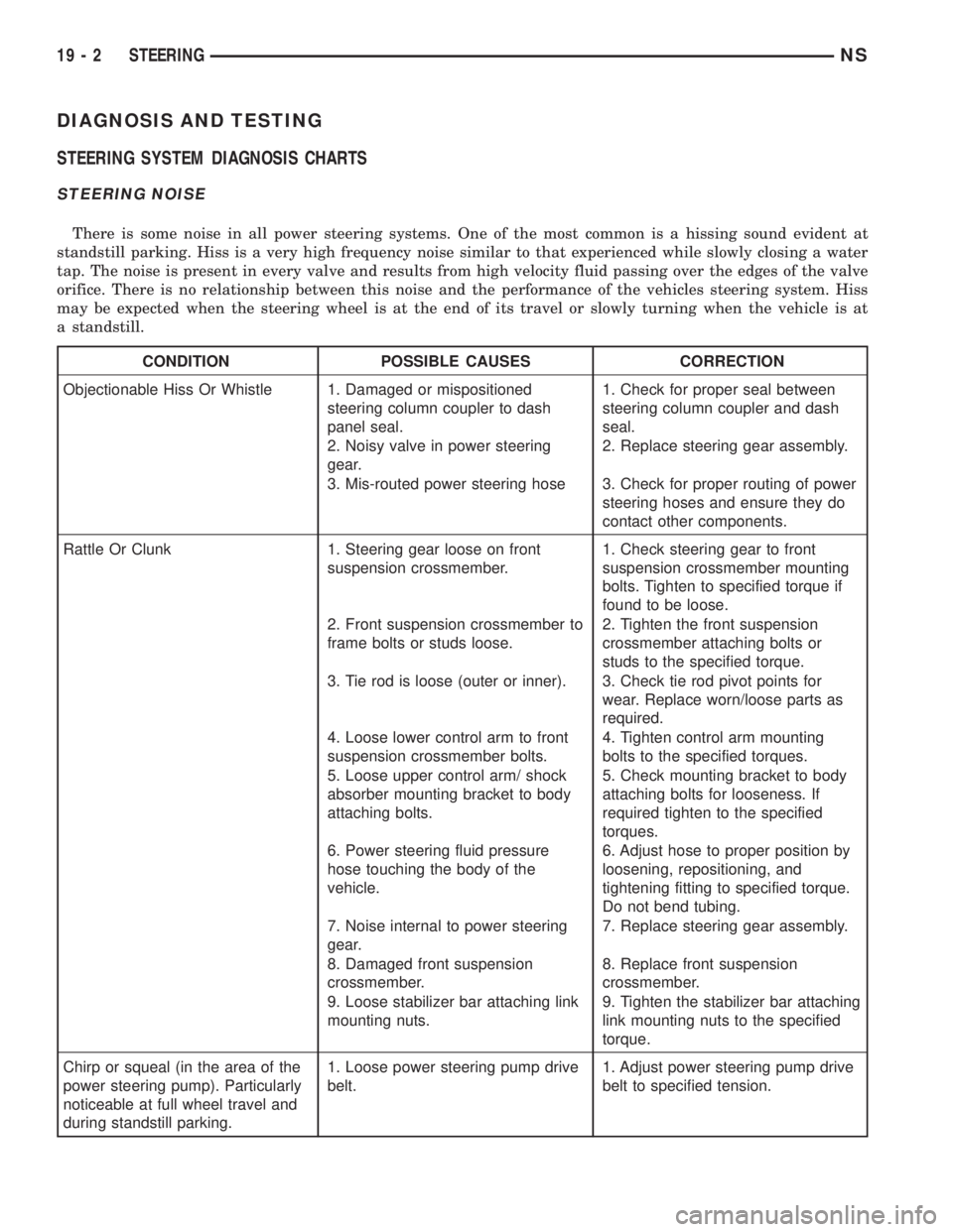
STEERING SYSTEM DIAGNOSIS CHARTS
STEERING NOISE
There is some noise in all power steering systems. One of the most common is a hissing sound evident at
standstill parking. Hiss is a very high frequency noise similar to that experienced while slowly closing a water
tap. The noise is present in every valve and results from high velocity fluid passing over the edges of the valve
orifice. There is no relationship between this noise and the performance of the vehicles steering system. Hiss
may be expected when the steering wheel is at the end of its travel or slowly turning when the vehicle is at
a standstill.
CONDITION POSSIBLE CAUSES CORRECTION
Objectionable Hiss Or Whistle 1. Damaged or mispositioned
steering column coupler to dash
panel seal.1. Check for proper seal between
steering column coupler and dash
seal.
2. Noisy valve in power steering
gear.2. Replace steering gear assembly.
3. Mis-routed power steering hose 3. Check for proper routing of power
steering hoses and ensure they do
contact other components.
Rattle Or Clunk 1. Steering gear loose on front
suspension crossmember.1. Check steering gear to front
suspension crossmember mounting
bolts. Tighten to specified torque if
found to be loose.
2. Front suspension crossmember to
frame bolts or studs loose.2. Tighten the front suspension
crossmember attaching bolts or
studs to the specified torque.
3. Tie rod is loose (outer or inner). 3. Check tie rod pivot points for
wear. Replace worn/loose parts as
required.
4. Loose lower control arm to front
suspension crossmember bolts.4. Tighten control arm mounting
bolts to the specified torques.
5. Loose upper control arm/ shock
absorber mounting bracket to body
attaching bolts.5. Check mounting bracket to body
attaching bolts for looseness. If
required tighten to the specified
torques.
6. Power steering fluid pressure
hose touching the body of the
vehicle.6. Adjust hose to proper position by
loosening, repositioning, and
tightening fitting to specified torque.
Do not bend tubing.
7. Noise internal to power steering
gear.7. Replace steering gear assembly.
8. Damaged front suspension
crossmember.8. Replace front suspension
crossmember.
9. Loose stabilizer bar attaching link
mounting nuts.9. Tighten the stabilizer bar attaching
link mounting nuts to the specified
torque.
Chirp or squeal (in the area of the
power steering pump). Particularly
noticeable at full wheel travel and
during standstill parking.1. Loose power steering pump drive
belt.1. Adjust power steering pump drive
belt to specified tension.
19 - 2 STEERINGNS
Page 1429 of 1938
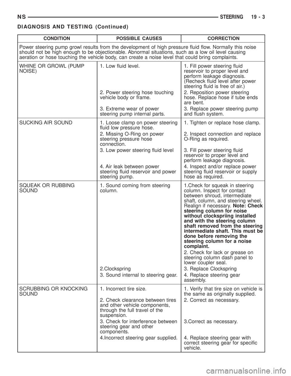
CONDITION POSSIBLE CAUSES CORRECTION
Power steering pump growl results from the development of high pressure fluid flow. Normally this noise
should not be high enough to be objectionable. Abnormal situations, such as a low oil level causing
aeration or hose touching the vehicle body, can create a noise level that could bring complaints.
WHINE OR GROWL (PUMP
NOISE)1. Low fluid level. 1. Fill power steering fluid
reservoir to proper level and
perform leakage diagnosis.
(Recheck fluid level after power
steering fluid is free of air.)
2. Power steering hose touching
vehicle body or frame.2. Reposition power steering
hose. Replace hose if tube ends
are bent.
3. Extreme wear of power
steering pump internal parts.3. Replace power steering pump
and flush system.
SUCKING AIR SOUND 1. Loose clamp on power steering
fluid low pressure hose.1. Tighten or replace hose clamp.
2. Missing O-Ring on power
steering pressure hose
connection.2. Inspect connection and replace
O-Ring as required.
3. Low power steering fluid level 3. Fill power steering fluid
reservoir to proper level and
perform leakage diagnosis.
4. Air leak between power
steering fluid reservoir and power
steering pump.4. Inspect and/or replace power
steering fluid reservoir or supply
hose as required.
SQUEAK OR RUBBING
SOUND1. Sound coming from steering
column.1.Check for squeak in steering
column. Inspect for contact
between shroud, intermediate
shaft, column, and steering wheel.
Realign if necessary.Note: Check
steering column for noise
without clockspriing installed
and with the steering column
shaft removed from the steering
intermediate shaft. This must be
done before removing the
steering column for a noise
complaint.
2. Check for lack or grease on
steering column dash panel to
lower coupler seal.
2.Clockspring 3. Replace Clockspring
3. Sound internal to steering gear. 4. Replace steering gear
assembly.
SCRUBBING OR KNOCKING
SOUND1. Incorrect tire size. 1. Verify that tire size on vehicle is
the same as originally supplied.
2. Check clearance between tires
and other vehicle components,
through the full travel of the
suspension.2. Correct as necessary.
3. Check for interference between
steering gear and other
components.3.Correct as necessary.
4.Incorrect steering gear supplied. 4. Replace steering gear with
correct steering gear for specific
vehicle.
NSSTEERING 19 - 3
DIAGNOSIS AND TESTING (Continued)
Page 1430 of 1938
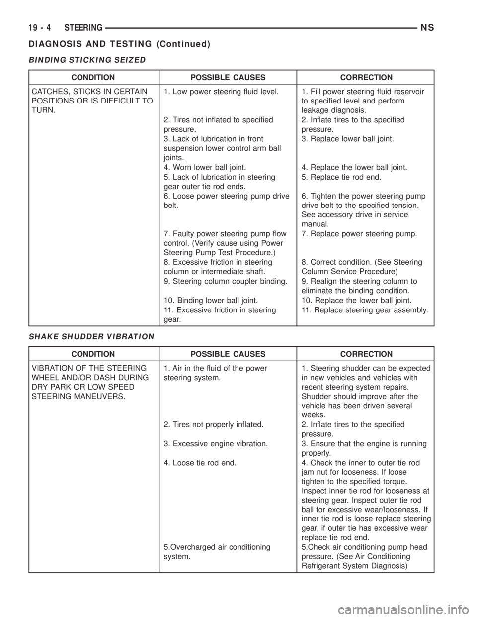
BINDING STICKING SEIZED
SHAKE SHUDDER VIBRATION
CONDITION POSSIBLE CAUSES CORRECTION
CATCHES, STICKS IN CERTAIN
POSITIONS OR IS DIFFICULT TO
TURN.1. Low power steering fluid level. 1. Fill power steering fluid reservoir
to specified level and perform
leakage diagnosis.
2. Tires not inflated to specified
pressure.2. Inflate tires to the specified
pressure.
3. Lack of lubrication in front
suspension lower control arm ball
joints.3. Replace lower ball joint.
4. Worn lower ball joint. 4. Replace the lower ball joint.
5. Lack of lubrication in steering
gear outer tie rod ends.5. Replace tie rod end.
6. Loose power steering pump drive
belt.6. Tighten the power steering pump
drive belt to the specified tension.
See accessory drive in service
manual.
7. Faulty power steering pump flow
control. (Verify cause using Power
Steering Pump Test Procedure.)7. Replace power steering pump.
8. Excessive friction in steering
column or intermediate shaft.8. Correct condition. (See Steering
Column Service Procedure)
9. Steering column coupler binding. 9. Realign the steering column to
eliminate the binding condition.
10. Binding lower ball joint. 10. Replace the lower ball joint.
11. Excessive friction in steering
gear.11. Replace steering gear assembly.
CONDITION POSSIBLE CAUSES CORRECTION
VIBRATION OF THE STEERING
WHEEL AND/OR DASH DURING
DRY PARK OR LOW SPEED
STEERING MANEUVERS.1. Air in the fluid of the power
steering system.1. Steering shudder can be expected
in new vehicles and vehicles with
recent steering system repairs.
Shudder should improve after the
vehicle has been driven several
weeks.
2. Tires not properly inflated. 2. Inflate tires to the specified
pressure.
3. Excessive engine vibration. 3. Ensure that the engine is running
properly.
4. Loose tie rod end. 4. Check the inner to outer tie rod
jam nut for looseness. If loose
tighten to the specified torque.
Inspect inner tie rod for looseness at
steering gear. Inspect outer tie rod
ball for excessive wear/looseness. If
inner tie rod is loose replace steering
gear, if outer tie has excessive wear
replace tie rod end.
5.Overcharged air conditioning
system.5.Check air conditioning pump head
pressure. (See Air Conditioning
Refrigerant System Diagnosis)
19 - 4 STEERINGNS
DIAGNOSIS AND TESTING (Continued)
Page 1432 of 1938
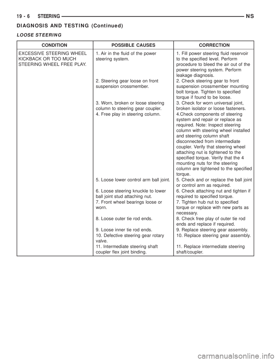
LOOSE STEERING
CONDITION POSSIBLE CAUSES CORRECTION
EXCESSIVE STEERING WHEEL
KICKBACK OR TOO MUCH
STEERING WHEEL FREE PLAY.1. Air in the fluid of the power
steering system.1. Fill power steering fluid reservoir
to the specified level. Perform
procedure to bleed the air out of the
power steering system. Perform
leakage diagnosis.
2. Steering gear loose on front
suspension crossmember.2. Check steering gear to front
suspension crossmember mounting
bolt torque. Tighten to specified
torque if found to be loose.
3. Worn, broken or loose steering
column to steering gear coupler.3. Check for worn universal joint,
broken isolator or loose fasteners.
4. Free play in steering column. 4.Check components of steering
system and repair or replace as
required. Note: Inspect steering
column with steering wheel installed
and steering column shaft
disconnected from intermediate
coupler. Verify that steering wheel
attaching nut is tightened to the
specified torque. Verify that the 4
mounting nuts for the steering
column are tightened to the specified
torque.
5. Loose lower control arm ball joint. 5. Check and or replace the ball joint
or control arm as required.
6. Loose steering knuckle to lower
ball joint stud attaching nut.6. Check attaching nut and tighten if
required to specified torque.
7. Front wheel bearings loose or
worn.7. Tighten hub nut to specified
torque or replace with new parts as
necessary.
8. Loose outer tie rod ends. 8. Check free play of outer tie rod
ends and replace if required.
9. Loose inner tie rod ends. 9. Replace steering gear assembly.
10. Defective steering gear rotary
valve.10. Replace steering gear assembly.
11. Intermediate steering shaft
coupler flex joint binding.11. Replace intermediate steering
shaft/coupler.
19 - 6 STEERINGNS
DIAGNOSIS AND TESTING (Continued)
Page 1433 of 1938
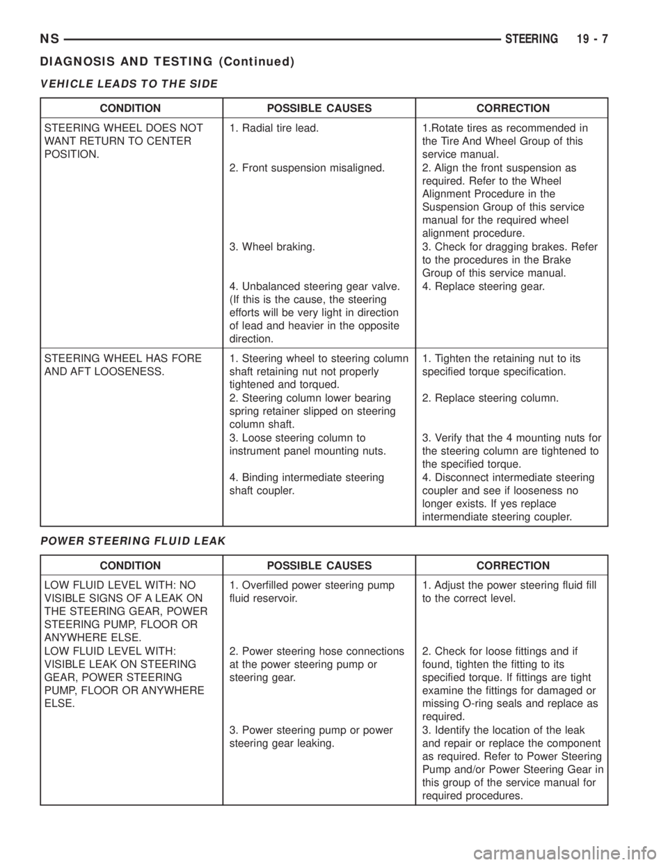
VEHICLE LEADS TO THE SIDE
POWER STEERING FLUID LEAK
CONDITION POSSIBLE CAUSES CORRECTION
STEERING WHEEL DOES NOT
WANT RETURN TO CENTER
POSITION.1. Radial tire lead. 1.Rotate tires as recommended in
the Tire And Wheel Group of this
service manual.
2. Front suspension misaligned. 2. Align the front suspension as
required. Refer to the Wheel
Alignment Procedure in the
Suspension Group of this service
manual for the required wheel
alignment procedure.
3. Wheel braking. 3. Check for dragging brakes. Refer
to the procedures in the Brake
Group of this service manual.
4. Unbalanced steering gear valve.
(If this is the cause, the steering
efforts will be very light in direction
of lead and heavier in the opposite
direction.4. Replace steering gear.
STEERING WHEEL HAS FORE
AND AFT LOOSENESS.1. Steering wheel to steering column
shaft retaining nut not properly
tightened and torqued.1. Tighten the retaining nut to its
specified torque specification.
2. Steering column lower bearing
spring retainer slipped on steering
column shaft.2. Replace steering column.
3. Loose steering column to
instrument panel mounting nuts.3. Verify that the 4 mounting nuts for
the steering column are tightened to
the specified torque.
4. Binding intermediate steering
shaft coupler.4. Disconnect intermediate steering
coupler and see if looseness no
longer exists. If yes replace
intermendiate steering coupler.
CONDITION POSSIBLE CAUSES CORRECTION
LOW FLUID LEVEL WITH: NO
VISIBLE SIGNS OF A LEAK ON
THE STEERING GEAR, POWER
STEERING PUMP, FLOOR OR
ANYWHERE ELSE.1. Overfilled power steering pump
fluid reservoir.1. Adjust the power steering fluid fill
to the correct level.
LOW FLUID LEVEL WITH:
VISIBLE LEAK ON STEERING
GEAR, POWER STEERING
PUMP, FLOOR OR ANYWHERE
ELSE.2. Power steering hose connections
at the power steering pump or
steering gear.2. Check for loose fittings and if
found, tighten the fitting to its
specified torque. If fittings are tight
examine the fittings for damaged or
missing O-ring seals and replace as
required.
3. Power steering pump or power
steering gear leaking.3. Identify the location of the leak
and repair or replace the component
as required. Refer to Power Steering
Pump and/or Power Steering Gear in
this group of the service manual for
required procedures.
NSSTEERING 19 - 7
DIAGNOSIS AND TESTING (Continued)
Page 1437 of 1938
REMOVAL AND INSTALLATION
2.4 LITER POWER STEERING PUMP
REMOVE
WARNING: POWER STEERING OIL, ENGINE COM-
PONENTS AND THE EXHAUST SYSTEM MAY BE
EXTREMELY HOT IF ENGINE HAS BEEN RUNNING.
DO NOT START ENGINE WITH ANY LOOSE OR DIS-
CONNECTED HOSES. DO NOT ALLOW HOSES TO
TOUCH HOT EXHAUST MANIFOLD OR CATALYST.
(1) Remove cap from power steering fluid reser-
voir.
(2) Using a siphon pump, remove as much power
steering fluid as possible from the power steering
fluid reservoir.
(3) Remove the (-) negative battery cable from the
battery and isolate cable.
(4) Remove the drive belt from the power steering
pump pulley. See Cooling, Group 7 for detailed
removal procedure.
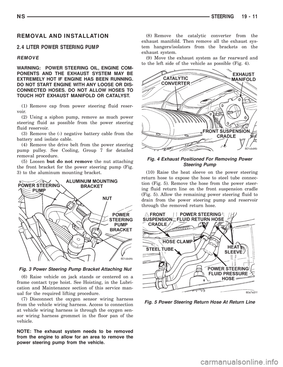
(5) Loosenbut do not removethe nut attaching
the front bracket for the power steering pump (Fig.
3) to the aluminum mounting bracket.
(6) Raise vehicle on jack stands or centered on a
frame contact type hoist. See Hoisting, in the Lubri-
cation and Maintenance section of this service man-
ual for the required lifting procedure.
(7) Disconnect the oxygen sensor wiring harness
from the vehicle wiring harness. Access to connection
at vehicle wiring harness is through the oxygen sen-
sor wiring harness grommet in the floor pan of the
vehicle.
NOTE: The exhaust system needs to be removed
from the engine to allow for an area to remove the
power steering pump from the vehicle.(8) Remove the catalytic converter from the
exhaust manifold. Then remove all the exhaust sys-
tem hangers/isolators from the brackets on the
exhaust system.
(9) Move the exhaust system as far rearward and
to the left side of the vehicle as possible (Fig. 4).
(10) Raise the heat sleeve on the power steering
return hose to expose the hose to steel tube connec-
tion (Fig. 5). Remove the hose from the power steer-
ing fluid return line on the front suspension cradle
(Fig. 5). Allow the remaining power steering fluid to
drain from the power steering pump and reservoir
through the removed return hose.
Fig. 3 Power Steering Pump Bracket Attaching Nut
Fig. 4 Exhaust Positioned For Removing Power
Steering Pump
Fig. 5 Power Steering Return Hose At Return Line
NSSTEERING 19 - 11
Page 1439 of 1938
(18) Remove the 3 previously loosened bolts
attaching the front bracket to the power steering
pump and separate the power steering pump from
the front bracket prior to removing the pump from
the vehicle.
(19) The power steering pump is removed from the
vehicle by pulling it out through the exhaust tunnel
area in the floor pan of the vehicle.
INSTALL
(1) Install power steering pump back in vehicle
using the reverse order of its removal through the
exhaust tunnel are of the vehicle.
(2) Install the power steering pump on its cast
mounting bracket and loosely install nut to hold
pump in place (Fig. 9).
(3) Install the front bracket on the power steering
pump and loosely install the 3 mounting bolts (Fig.
10). Then install the nut and bolt attaching the front
bracket to the cast bracket (Fig. 10).
(4) Tighten the 3 power steering pump mounting
bolts (Fig. 10) to a torque of 54 N´m (40 ft. lbs.).
NOTE: Before installing power steering fluid pres-
sure hose on power steering pump, inspect the
O-ring on the pressure hose for damage and
replace if necessary.
(5) Install the power steering fluid pressure line
onto the output fitting of the power steering pump
(Fig. 8). Tighten the pressure line to pump fitting
tube nut to a torque of 31 N´m (275 in. lbs.).
(6) Install the power steering fluid, low pressure
return hose on the power steering pump low pressure
fitting (Fig. 8).Be sure hose clamps are properly
reinstalled.
(7) Install the power steering fluid supply hose
from the power steering fluid reservoir, on the power
steering pump fluid fitting (Fig. 7).Be sure hose is
clear of accessory drive belts all hose clamps
are properly reinstalled.
(8) Install the power steering pump drive belt on
pulley. See Cooling, Group 7 for detailed installation
procedure.
(9) Install the accessory drive splash shield (Fig.
6).
(10) Install the power steering fluid return hose on
the steel tube at the front suspension cradle (Fig. 5).
(11) Install a screw type hose clamp on the power
steering hose to steel tube connection.Be sure hose
clamps are properly reinstalled.Tighten the screw
clamp to a torque of 2 N´m (18 in. lbs.).
CAUTION: The protective heat shield sleeves must
cover the entire rubber hose and hose to tube con-
nection portion of both the power steering fluid
pressure and return hoses (Fig. 5). This is requiredto prevent the overheating of the power steering
hoses.
(12) When used, properly position the protective
heat sleeves on the power steering hoses (Fig. 5).
Then, tie strap the heat sleeves to the power steering
hoses to keep them in their proper position.
(13) Install the exhaust pipe on the exhaust man-
ifold. Install all exhaust system hangers/isolators on
the exhaust system brackets.
(14) Connect the oxygen sensor wiring harness to
the vehicle wiring harness. Install wiring harness
grommet in the floor pan of the vehicle.
(15) Lower vehicle.
(16) Adjust the power steering pump drive belt.
See Cooling, Group 7 for detailed adjustment proce-
dure.
(17) Tighten the top nut and bottom bolt on the
power steering pump front mounting bracket (Fig. 3)
to a torque of 54 N´m (40 ft. lbs.).
CAUTION: Do not use automatic transmission fluid
in power steering system. Only use MoparT, Power
Steering Fluid, or equivalent.
(18) Fill the remote power steering pump fluid res-
ervoir to correct fluid level.
(19) Install cap on power steering fluid reservoir.
(20) Connect the negative battery cable on the
negative battery post.
(21) Start engine and turn steering wheel several
times from stop to stop to bleed air from fluid in sys-
tem. Stop engine, check fluid level, and inspect sys-
tem for leaks. See Checking Fluid Level.
3.0 LITER POWER STEERING PUMP
REMOVE
WARNING: POWER STEERING OIL, ENGINE COM-
PONENTS AND THE EXHAUST SYSTEM MAY BE
EXTREMELY HOT IF ENGINE HAS BEEN RUNNING.
DO NOT START ENGINE WITH ANY LOOSE OR DIS-
CONNECTED HOSES. DO NOT ALLOW HOSES TO
TOUCH HOT EXHAUST MANIFOLD OR CATALYST.
(1) Remove the (-) negative battery cable from the
battery and isolate cable.
(2) Remove cap from power steering fluid reser-
voir.
(3) Using a siphon pump, remove as much power
steering fluid as possible from the power steering
fluid reservoir.
NSSTEERING 19 - 13
REMOVAL AND INSTALLATION (Continued)
Page 1440 of 1938
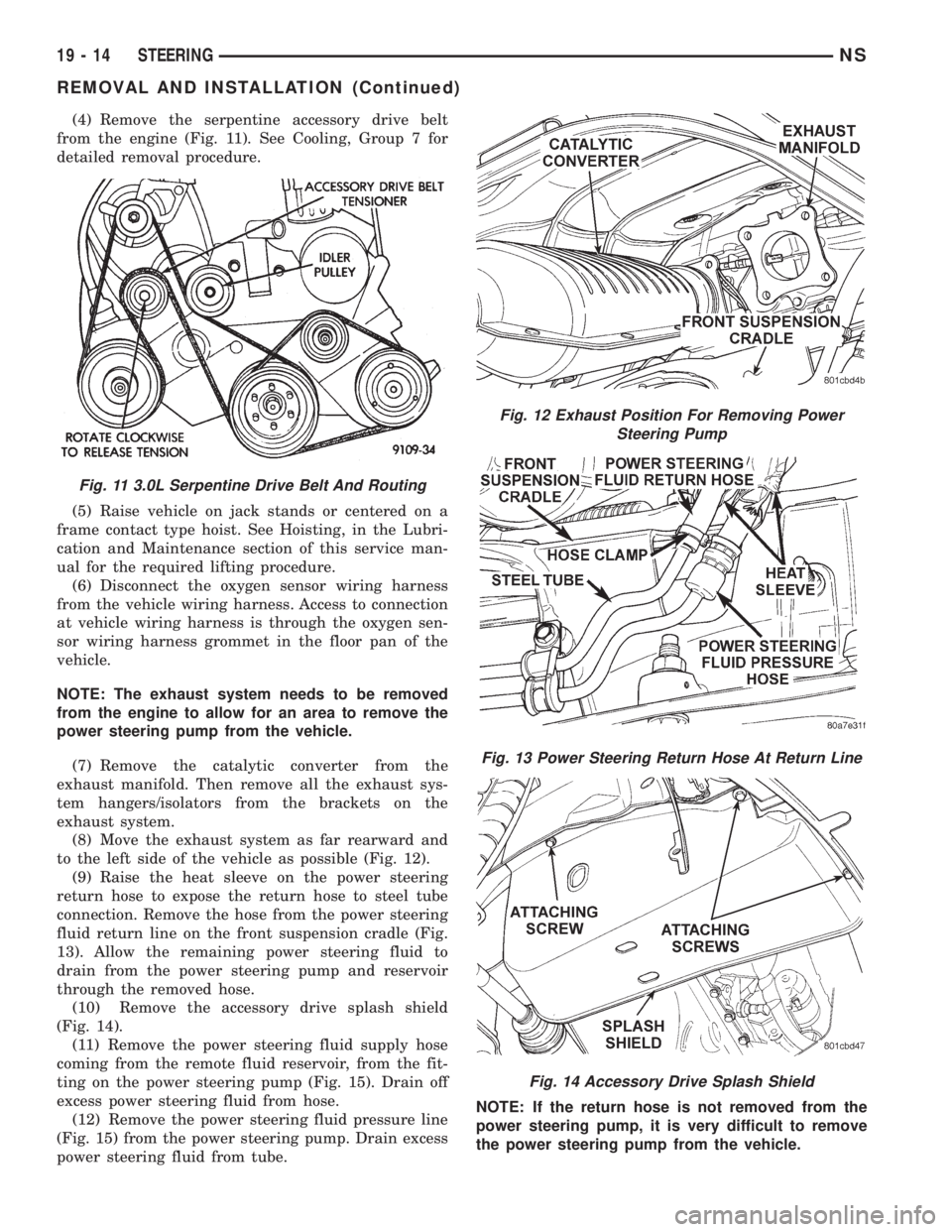
(4) Remove the serpentine accessory drive belt
from the engine (Fig. 11). See Cooling, Group 7 for
detailed removal procedure.
(5) Raise vehicle on jack stands or centered on a
frame contact type hoist. See Hoisting, in the Lubri-
cation and Maintenance section of this service man-
ual for the required lifting procedure.
(6) Disconnect the oxygen sensor wiring harness
from the vehicle wiring harness. Access to connection
at vehicle wiring harness is through the oxygen sen-
sor wiring harness grommet in the floor pan of the
vehicle.
NOTE: The exhaust system needs to be removed
from the engine to allow for an area to remove the
power steering pump from the vehicle.
(7) Remove the catalytic converter from the
exhaust manifold. Then remove all the exhaust sys-
tem hangers/isolators from the brackets on the
exhaust system.
(8) Move the exhaust system as far rearward and
to the left side of the vehicle as possible (Fig. 12).
(9) Raise the heat sleeve on the power steering
return hose to expose the return hose to steel tube
connection. Remove the hose from the power steering
fluid return line on the front suspension cradle (Fig.
13). Allow the remaining power steering fluid to
drain from the power steering pump and reservoir
through the removed hose.
(10) Remove the accessory drive splash shield
(Fig. 14).
(11) Remove the power steering fluid supply hose
coming from the remote fluid reservoir, from the fit-
ting on the power steering pump (Fig. 15). Drain off
excess power steering fluid from hose.
(12) Remove the power steering fluid pressure line
(Fig. 15) from the power steering pump. Drain excess
power steering fluid from tube.NOTE: If the return hose is not removed from the
power steering pump, it is very difficult to remove
the power steering pump from the vehicle.
Fig. 11 3.0L Serpentine Drive Belt And Routing
Fig. 12 Exhaust Position For Removing Power
Steering Pump
Fig. 13 Power Steering Return Hose At Return Line
Fig. 14 Accessory Drive Splash Shield
19 - 14 STEERINGNS
REMOVAL AND INSTALLATION (Continued)