1996 CHRYSLER VOYAGER suspension
[x] Cancel search: suspensionPage 194 of 1938

SPECIFICATIONS
SPEED SENSOR TONE WHEEL RUNOUT
The total indicator runout allowed for both the
front and rear tone wheel measured using a dial indi-
cator is 0.15 mm (.006 in.).
WHEEL SPEED SENSOR TO TONE WHEEL
CLEARANCE
FRONT WHEEL
Minimum Clearance .35mm (.014 in.)
Maxamum Clearance 1.2 mm (.047 in.)
REAR WHEEL
Minimum Clearance .40mm (.016 in.)
Maxamum Clearance 1.2 mm (.047 in.)
BRAKE FASTENER TORQUE SPECIFICATIONS
DESCRIPTION TORQUE
BRAKE TUBES:
Tube Nuts To Fittings And
Components..............17N´m(145 in. lbs.)
BRAKE HOSE:
To Caliper Banjo Bolt..........48N´m(35ft.lbs.)
Intermediate Bracket.........12N´m(105 in. lbs.)
MASTER CYLINDER:
To Vacuum Booster
Mounting Nut............25N´m(225 in. lbs.)
FIXED PROPORTIONING VALVE:
To Frame Rail Attaching
Bolts....................14N´m(125 in. lbs.)
HEIGHT SENSING PROPORTIONING VALVE:
To Mounting Bracket
Attaching Bolts...........23N´m(200 in. lbs.)
Actuator Assembly
Adjustment Nut.............5N´m(45in.lbs.)
Mounting Bracket To
Frame Rail Bolts..........17N´m(150 in. lbs.)
JUNCTION BLOCK (NON-ABS BRAKES)
To Suspension Cradle
Mounting Bolt............28N´m(250 in. lbs.)
VACUUM BOOSTER:
To Dash Panel Mounting
Nuts....................28N´m(250 in. lbs.)DESCRIPTION TORQUE
REAR WHEEL CYLINDER:
To Support Plate Mounting
Bolts.....................8N´m(75in.lbs.)
Bleeder Screw...............10N´m(80in.lbs.)
BRAKE SUPPORT PLATE:
To Rear Axle Mounting Bolts . . .130 N´m (95 ft. lbs.)
DISC BRAKE CALIPER:
Guide Pin Bolts..............41N´m(30ft.lbs.)
Bleeder Screw..............15N´m(125 in. lbs.)
ABS HYDRAULIC CONTROL UNIT:
Mounting Bracket To
Suspension Cradle Bolts.....28N´m(250 in. lbs.)
To Mounting Bracket Isolator
Attaching Bolts............11N´m(97in.lbs.)
CAB To HCU Mounting Screws . . .2 N´m (17 in. lbs.)
WHEEL SPEED SENSOR:
To Axle Or Steering Knuckle
Mounting Bolt............12N´m(105 in. lbs.)
PARKING BRAKE:
Pedal Assembly Mounting
Bolts....................28N´m(250 in. lbs.)
REAR HUB AND BEARING:
To Axle Mounting Bolts........129 N´m (95 ft. lbs.)
WHEEL:
Stud Lug Nut........115±156 N´m (84-115 ft. lbs.)
5 - 112 BRAKESNS
Page 204 of 1938

CLUTCH DIAGNOSIS
Problem diagnosis will generally require a road
test to determine the type of fault. Component
inspection will then determine the problem after road
testing.
Drive the vehicle at normal speeds during road
test. Shift the transaxle through all gear ranges andobserve clutch action. If chatter, grab, slip, or
improper release is experienced, remove and inspect
the clutch components. If the problem is noise or
hard shifting, further diagnosis may be needed. The
transaxle or other driveline components may actually
be at fault.
SERVICE DIAGNOSIS±CLUTCH GRAB/CHATTER
CONDITION POSSIBLE CAUSES CORRECTION
CLUTCH DISC FACING
COVERED WITH OIL OR
GREASEOil leak at engine rear main or transaxle
input shaft sealCorrect leak and replace clutch assembly
NO FAULT FOUND WITH
CLUTCH
COMPONENTSProblem actually related to suspension
or driveline componentFurther diagnosis required. Check
engine/transmission mounts, suspension
attaching parts and other driveline
components as needed.
Engine related problems Check EFI and ignition systems
PARTIAL ENGAGEMENT
OF CLUTCH DISCClutch cover, spring, or release fingers
bent, distorted (rough handling, improper
assembly)Replace clutch assembly
Clutch disc damaged or distorted Replace clutch assembly
Clutch misalignment Check alignment and runout of flywheel,
disc, or cover. Check clutch housing to
engine dowels and dowel holes for
damage. Correct as necessary.
SERVICE DIAGNOSIS±CLUTCH SLIPS
CONDITION POSSIBLE CAUSES CORRECTION
DISC FACING WORN
OUTNormal wear. Replace clutch assembly.
Driver frequently rides (slips) clutch,
results in rapid wear overheating.Replace clutch assembly
Insufficient clutch cover diaphragm
spring tensionReplace clutch assembly
CLUTCH DISC FACING
CONTAMINATED WITH
OIL OR GREASELeak at rear main oil seal or transaxle
input shaft sealReplace leaking seals. Replace clutch
assembly.
Road splash, water entering housing Seal housing. Inspect clutch assembly.
CLUTCH IS RUNNING
PARTIALLY
DISENGAGEDRelease bearing sticking or binding,
does not return to normal running
position.Verify that bearing is actually binding.
Then, replace bearing and transmission
front bearing retainer if sleeve surface is
damaged.
Cable self-adjuster mechanism sticking
or binding causing high preload (LHD
Applications only)Verify that self-adjuster is free to move
(LHD Applications only)
CLUTCH DISC FACINGS
HAVE FRACTURED INTO
SMALL PIECESDriver performs a 5-1 downshift at
vehicle speed in excess of 60 miles per
hourAlert driver to problem cause. Replace
clutch assembly.
Excessive heat from slippage Replace clutch assembly
6 - 6 CLUTCHNS/GS
DIAGNOSIS AND TESTING (Continued)
Page 457 of 1938

HEADLAMP ALIGNMENT
INDEX
page page
GENERAL INFORMATION
HEADLAMP ALIGNMENT................... 5
SERVICE PROCEDURES
HEADLAMP ALIGNMENT PREPARATION....... 5ADJUSTMENTS
HEADLAMP/FOG LAMP ADJUSTMENT USING
ALIGNMENT SCREEN.................... 5
GENERAL INFORMATION
HEADLAMP ALIGNMENT
The headlamps are equipped with a bubble level
for up/down headlamp alignment. The bubble is cen-
tered with the vehicle on a level surface. A horizontal
gauge and magnifying window is located next to the
bubble level for left/right alignment (Fig. 1). Aim on
every headlamp assembly is calibrated at the head-
lamp manufacturer. At the vehicle assembly plant,
the vertical aim is set by centering the bubble with
the vehicle on a level surface. Horizontal aim is con-
trolled by the mounting pads on each headlamp
mounting panel.
When the vehicle is to be used with a heavy load,
the bubble level can be used to compensate for the
altered ride height.
SERVICE PROCEDURES
HEADLAMP ALIGNMENT PREPARATION
(1) Verify headlamp dimmer switch and high beam
indicator operation.
(2) Inspect and correct damaged or defective com-
ponents that could interfere with proper headlamp
alignment.
(3) Verify proper tire inflation.
(4) Clean headlamp lenses.
(5) Verify that luggage area is loaded as the vehi-
cle is routinely used.
(6) Fuel tank should be FULL. Add 2.94 kg (6.5
lbs.) of weight over the fuel tank for each estimated
gallon of missing fuel.
ADJUSTMENTS
HEADLAMP/FOG LAMP ADJUSTMENT USING
ALIGNMENT SCREEN
ALIGNMENT SCREEN PREPARATION
(1) Position vehicle on a level surface perpendicu-
lar to a flat wall 7.62 meters (25 ft.) away from front
of headlamp lens (Fig. 2).
(2) If necessary, tape a line on the floor 7.62
meters (25 ft.) away from and parallel to the wall.
(3) From the floor up 1.27 meters (5 ft.), tape a
line on the wall at the center line of the vehicle.
Sight along the center line of the vehicle (from rear
of vehicle forward) to verify accuracy of the line
placement.
(4) Rock vehicle side-to-side three times and allow
suspension to stabilize.
(5) Jounce front suspension three times by pushing
downward on front bumper and releasing.
(6) Measure the distance from the center of head-
lamp lens to the floor. Transfer measurement to the
alignment screen (with tape). Use this line for
up/down adjustment reference.
(7) Measure distance from the center line of the
vehicle to the center of each headlamp being aligned.
Transfer measurements to screen (with tape) to each
Fig. 1 Magnifying Window and Bubble Level
NSLAMPS 8L - 5
Page 484 of 1938

(5) Rock vehicle side-to-side three times and allow
suspension to stabilize.
(6) Jounce front suspension three times by pushing
downward on front bumper and releasing.
(7) Measure the distance from the center of head-
lamp lens to the floor. Transfer measurement to the
alignment screen (with tape). Use this line for
up/down adjustment reference.
(8) Place a tape line 130 mm below and parallel to
the center of headlamp line.
(9) Measure distance from the centerline of the
vehicle to the center of each headlamp being aligned.
Transfer measurements to screen (with tape) to each
side of vehicle centerline. Use these lines for left/
right adjustment reference.HEADLAMP ADJUSTMENT
A properly aimed low beam headlamp will project a
high intensity light pattern on the screen with the
horizontal cut-off line aligned with the tape line 130
mm (5.12 in.) below the headlamp centerline (Fig. 1).
The intersection of the horizontal and 15 degree cut-
off lines in the projected pattern should align to the
intersection of the headlamp centerline vertical tape
line and the tape line 130 mm (5.12 in.) below the
headlamp horizontal centerline. The high beams on a
vehicle with aero headlamps cannot be aligned. The
high beam pattern should be correct when the low
beams are aligned properly.
Fig. 1 Headlamp Alignment Screen
8L - 6 LAMPSNS/GS
ADJUSTMENTS (Continued)
Page 566 of 1938

CIRCUIT INFORMATION
Each wire shown in the diagrams contains a code
which identifies the main circuit, part of the main
circuit, gage of wire, and color (Fig. 1).
CIRCUIT FUNCTIONS
All circuits in the diagrams use an alpha/numeric
code to identify the wire and its function. To identify
which circuit code applies to a system, refer to the
Circuit Identification Code Chart. This chart shows
the main circuits only and does not show the second-
ary codes that may apply to some models.
Fig. 1 Wire Code Identification
COLOR CODE COLORSTANDARD
TRACER
COLOR
BL BLUE WT
BK BLACK WT
BR BROWN WT
DB DARK BLUE WT
DG DARK GREEN WT
GY GRAY BK
LB LIGHT BLUE BK
LG LIGHT GREEN BK
OR ORANGE BK
PK PINK BK or WT
RD RED WT
TN TAN WT
VT VIOLET WT
WT WHITE BK
YL YELLOW BK
* WITH TRACER
CIRCUIT FUNCTION
A BATTERY FEED
B BRAKE CONTROLS
C CLIMATE CONTROLS
D DIAGNOSTIC CIRCUITS
E DIMMING ILLUMINATION CIRCUITS
F FUSED CIRCUITS
G MONITORING CIRCUITS (GAUGES)
H OPEN
I NOT USED
J OPEN
K POWERTRAIN CONTROL MODULE
L EXTERIOR LIGHTING
M INTERIOR LIGHTING
N NOT USED
O NOT USED
P POWER OPTION (BATTERY FEED)
Q POWER OPTIONS (IGNITION FEED)
R PASSIVE RESTRAINT
S SUSPENSION/STEERING
T TRANSMISSION/TRANSAXLE/
TRANSFER CASE
U OPEN
V SPEED CONTROL, WIPER/WASHER
W OPEN
X AUDIO SYSTEMS
Y OPEN
Z GROUNDS
8W - 01 - 4 8W-01 GENERAL INFORMATIONNS/GS
DESCRIPTION AND OPERATION (Continued)
Page 1075 of 1938

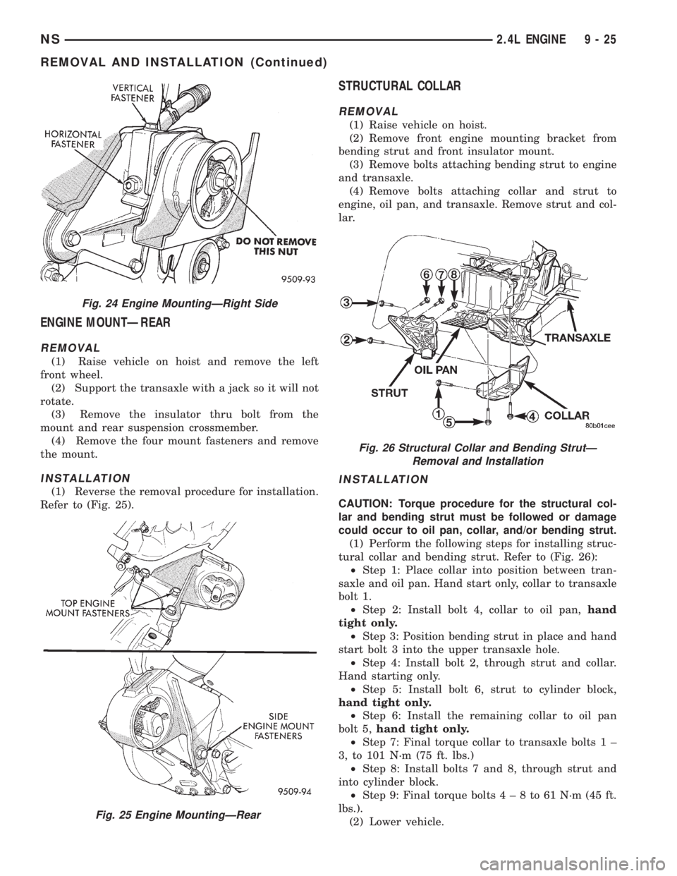
ENGINE MOUNTÐREAR
REMOVAL
(1) Raise vehicle on hoist and remove the left
front wheel.
(2) Support the transaxle with a jack so it will not
rotate.
(3) Remove the insulator thru bolt from the
mount and rear suspension crossmember.
(4) Remove the four mount fasteners and remove
the mount.
INSTALLATION
(1) Reverse the removal procedure for installation.
Refer to (Fig. 25).
STRUCTURAL COLLAR
REMOVAL
(1) Raise vehicle on hoist.
(2) Remove front engine mounting bracket from
bending strut and front insulator mount.
(3) Remove bolts attaching bending strut to engine
and transaxle.
(4) Remove bolts attaching collar and strut to
engine, oil pan, and transaxle. Remove strut and col-
lar.
INSTALLATION
CAUTION: Torque procedure for the structural col-
lar and bending strut must be followed or damage
could occur to oil pan, collar, and/or bending strut.
(1) Perform the following steps for installing struc-
tural collar and bending strut. Refer to (Fig. 26):
²Step 1: Place collar into position between tran-
saxle and oil pan. Hand start only, collar to transaxle
bolt 1.
²Step 2: Install bolt 4, collar to oil pan,hand
tight only.
²Step 3: Position bending strut in place and hand
start bolt 3 into the upper transaxle hole.
²Step 4: Install bolt 2, through strut and collar.
Hand starting only.
²Step 5: Install bolt 6, strut to cylinder block,
hand tight only.
²Step 6: Install the remaining collar to oil pan
bolt 5,hand tight only.
²Step 7: Final torque collar to transaxle bolts 1 ±
3, to 101 N´m (75 ft. lbs.)
²Step 8: Install bolts 7 and 8, through strut and
into cylinder block.
²Step 9: Final torque bolts4±8to61N´m(45ft.
lbs.).
(2) Lower vehicle.
Fig. 24 Engine MountingÐRight Side
Fig. 25 Engine MountingÐRear
Fig. 26 Structural Collar and Bending StrutÐ
Removal and Installation
NS2.4L ENGINE 9 - 25
REMOVAL AND INSTALLATION (Continued)
Page 1104 of 1938

CYLINDER BLOCK
(1) Clean cylinder block thoroughly and check all
core hole plugs for evidence of leaking.
(2) If new core plugs are installed, refer to Engine
Core Plugs outlined in this section.
(3) Examine block and cylinder bores for cracks or
fractures.
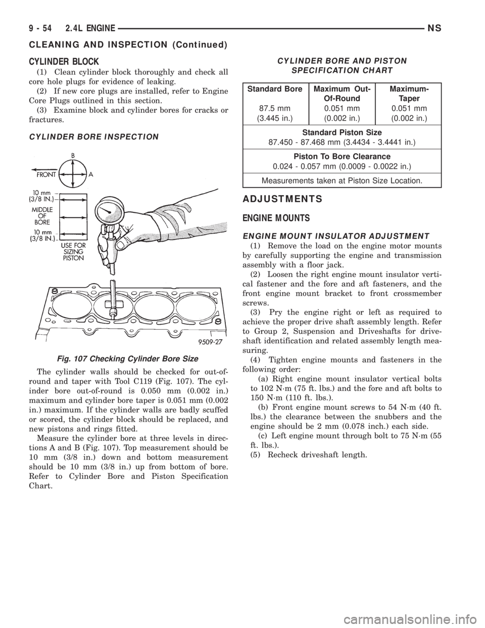
CYLINDER BORE INSPECTION
The cylinder walls should be checked for out-of-
round and taper with Tool C119 (Fig. 107). The cyl-
inder bore out-of-round is 0.050 mm (0.002 in.)
maximum and cylinder bore taper is 0.051 mm (0.002
in.) maximum. If the cylinder walls are badly scuffed
or scored, the cylinder block should be replaced, and
new pistons and rings fitted.
Measure the cylinder bore at three levels in direc-
tions A and B (Fig. 107). Top measurement should be
10 mm (3/8 in.) down and bottom measurement
should be 10 mm (3/8 in.) up from bottom of bore.
Refer to Cylinder Bore and Piston Specification
Chart.
ADJUSTMENTS
ENGINE MOUNTS
ENGINE MOUNT INSULATOR ADJUSTMENT
(1) Remove the load on the engine motor mounts
by carefully supporting the engine and transmission
assembly with a floor jack.
(2) Loosen the right engine mount insulator verti-
cal fastener and the fore and aft fasteners, and the
front engine mount bracket to front crossmember
screws.
(3) Pry the engine right or left as required to
achieve the proper drive shaft assembly length. Refer
to Group 2, Suspension and Driveshafts for drive-
shaft identification and related assembly length mea-
suring.
(4) Tighten engine mounts and fasteners in the
following order:
(a) Right engine mount insulator vertical bolts
to 102 N´m (75 ft. lbs.) and the fore and aft bolts to
150 N´m (110 ft. lbs.).
(b) Front engine mount screws to 54 N´m (40 ft.
lbs.) the clearance between the snubbers and the
engine should be 2 mm (0.078 inch.) each side.
(c) Left engine mount through bolt to 75 N´m (55
ft. lbs.).
(5) Recheck driveshaft length.
Fig. 107 Checking Cylinder Bore Size
CYLINDER BORE AND PISTON
SPECIFICATION CHART
Standard Bore Maximum Out-
Of-RoundMaximum-
Taper
87.5 mm 0.051 mm 0.051 mm
(3.445 in.) (0.002 in.) (0.002 in.)
Standard Piston Size
87.450 - 87.468 mm (3.4434 - 3.4441 in.)
Piston To Bore Clearance
0.024 - 0.057 mm (0.0009 - 0.0022 in.)
Measurements taken at Piston Size Location.
9 - 54 2.4L ENGINENS
CLEANING AND INSPECTION (Continued)
Page 1119 of 1938

(2) Tighten mount to transmission bolts to 55 N´m
(40 ft. lbs.) (Fig. 22).
Tighten through bolt to 75 N´m (55 ft. lbs.)
(3) Engine mount adjustment, Refer to Engine
Mount Insulator Adjustment of this section.
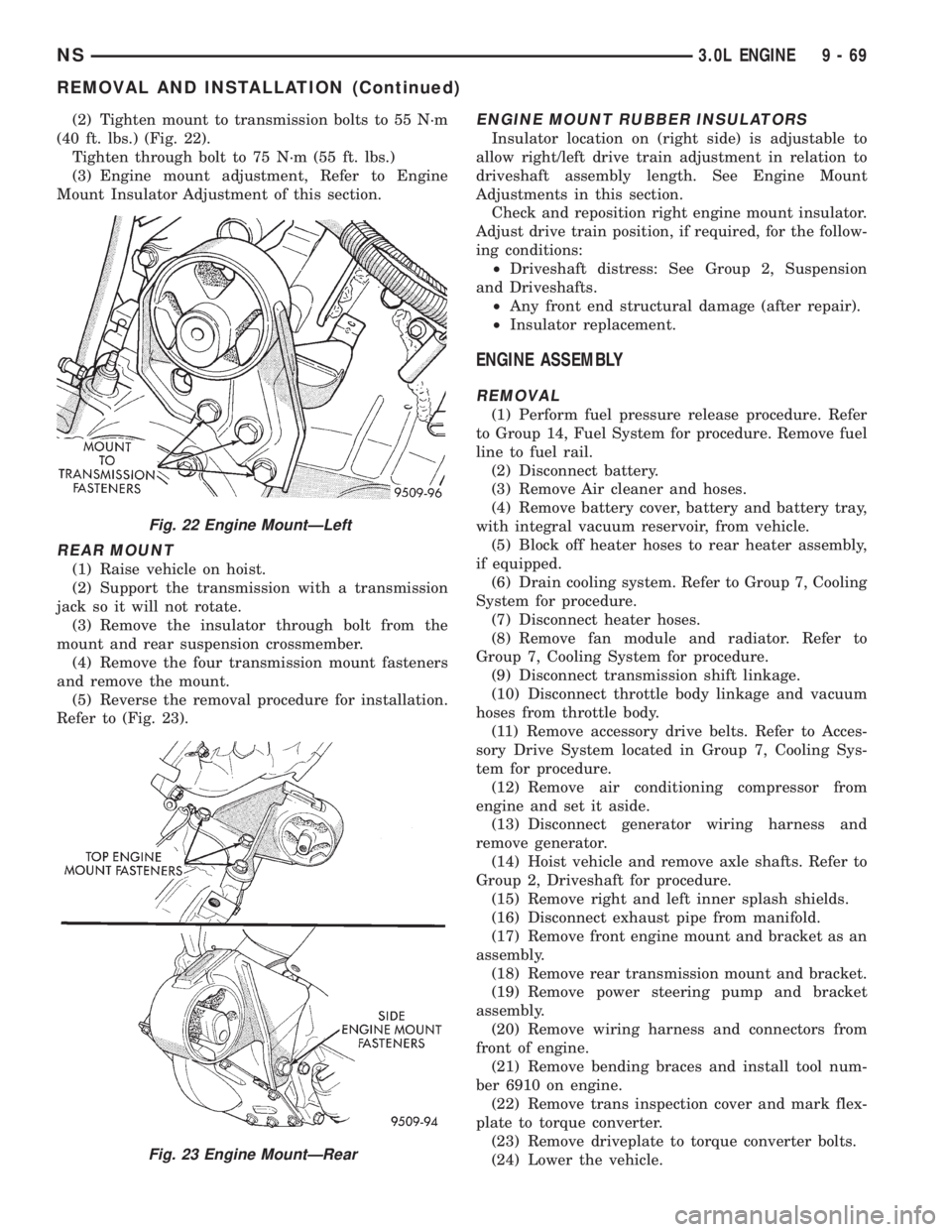
REAR MOUNT
(1) Raise vehicle on hoist.
(2) Support the transmission with a transmission
jack so it will not rotate.
(3) Remove the insulator through bolt from the
mount and rear suspension crossmember.
(4) Remove the four transmission mount fasteners
and remove the mount.
(5) Reverse the removal procedure for installation.
Refer to (Fig. 23).
ENGINE MOUNT RUBBER INSULATORS
Insulator location on (right side) is adjustable to
allow right/left drive train adjustment in relation to
driveshaft assembly length. See Engine Mount
Adjustments in this section.
Check and reposition right engine mount insulator.
Adjust drive train position, if required, for the follow-
ing conditions:
²Driveshaft distress: See Group 2, Suspension
and Driveshafts.
²Any front end structural damage (after repair).
²Insulator replacement.
ENGINE ASSEMBLY
REMOVAL
(1) Perform fuel pressure release procedure. Refer
to Group 14, Fuel System for procedure. Remove fuel
line to fuel rail.
(2) Disconnect battery.
(3) Remove Air cleaner and hoses.
(4) Remove battery cover, battery and battery tray,
with integral vacuum reservoir, from vehicle.
(5) Block off heater hoses to rear heater assembly,
if equipped.
(6) Drain cooling system. Refer to Group 7, Cooling
System for procedure.
(7) Disconnect heater hoses.
(8) Remove fan module and radiator. Refer to
Group 7, Cooling System for procedure.
(9) Disconnect transmission shift linkage.
(10) Disconnect throttle body linkage and vacuum
hoses from throttle body.
(11) Remove accessory drive belts. Refer to Acces-
sory Drive System located in Group 7, Cooling Sys-
tem for procedure.
(12) Remove air conditioning compressor from
engine and set it aside.
(13) Disconnect generator wiring harness and
remove generator.
(14) Hoist vehicle and remove axle shafts. Refer to
Group 2, Driveshaft for procedure.
(15) Remove right and left inner splash shields.
(16) Disconnect exhaust pipe from manifold.
(17) Remove front engine mount and bracket as an
assembly.
(18) Remove rear transmission mount and bracket.
(19) Remove power steering pump and bracket
assembly.
(20) Remove wiring harness and connectors from
front of engine.
(21) Remove bending braces and install tool num-
ber 6910 on engine.
(22) Remove trans inspection cover and mark flex-
plate to torque converter.
(23) Remove driveplate to torque converter bolts.
(24) Lower the vehicle.
Fig. 22 Engine MountÐLeft
Fig. 23 Engine MountÐRear
NS3.0L ENGINE 9 - 69
REMOVAL AND INSTALLATION (Continued)