1996 CHRYSLER VOYAGER suspension
[x] Cancel search: suspensionPage 1138 of 1938
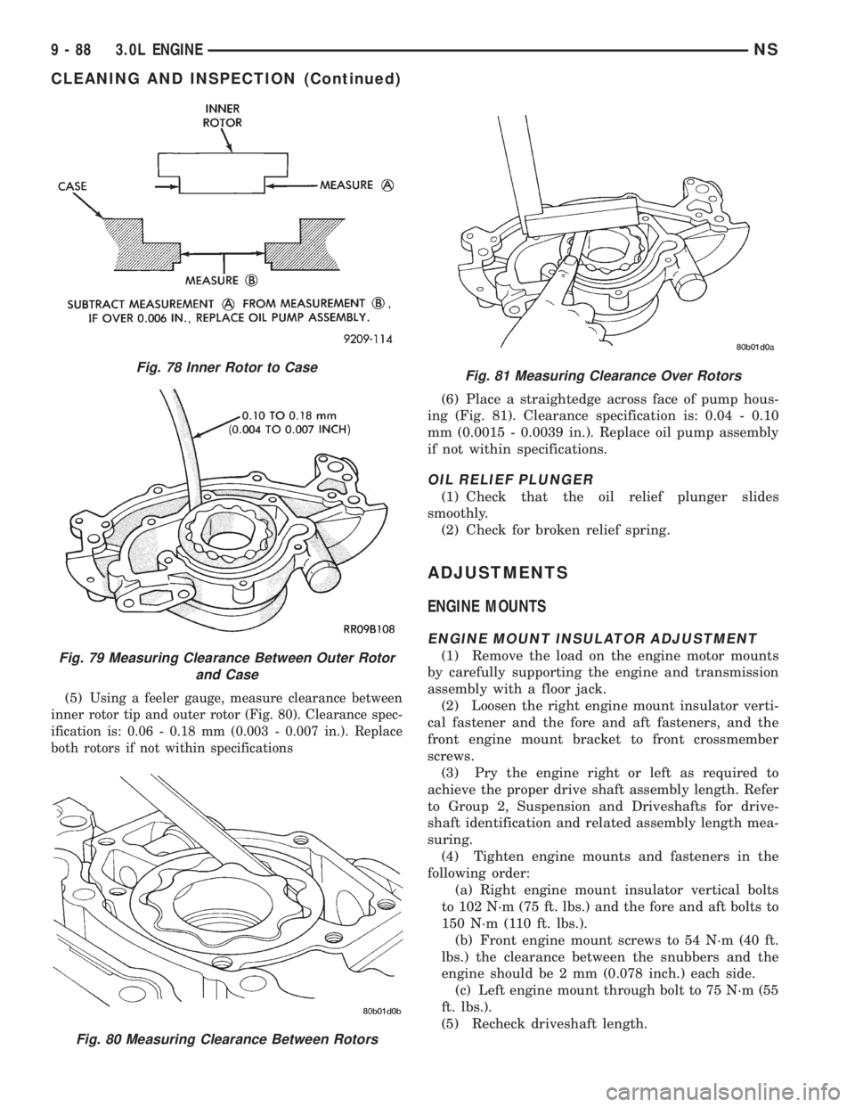
(5)Using a feeler gauge, measure clearance between
inner rotor tip and outer rotor (Fig. 80). Clearance spec-
ification is: 0.06 - 0.18 mm (0.003 - 0.007 in.). Replace
both rotors if not within specifications
(6) Place a straightedge across face of pump hous-
ing (Fig. 81). Clearance specification is: 0.04 - 0.10
mm (0.0015 - 0.0039 in.). Replace oil pump assembly
if not within specifications.
OIL RELIEF PLUNGER
(1) Check that the oil relief plunger slides
smoothly.
(2) Check for broken relief spring.
ADJUSTMENTS
ENGINE MOUNTS
ENGINE MOUNT INSULATOR ADJUSTMENT
(1) Remove the load on the engine motor mounts
by carefully supporting the engine and transmission
assembly with a floor jack.
(2) Loosen the right engine mount insulator verti-
cal fastener and the fore and aft fasteners, and the
front engine mount bracket to front crossmember
screws.
(3) Pry the engine right or left as required to
achieve the proper drive shaft assembly length. Refer
to Group 2, Suspension and Driveshafts for drive-
shaft identification and related assembly length mea-
suring.
(4) Tighten engine mounts and fasteners in the
following order:
(a) Right engine mount insulator vertical bolts
to 102 N´m (75 ft. lbs.) and the fore and aft bolts to
150 N´m (110 ft. lbs.).
(b) Front engine mount screws to 54 N´m (40 ft.
lbs.) the clearance between the snubbers and the
engine should be 2 mm (0.078 inch.) each side.
(c) Left engine mount through bolt to 75 N´m (55
ft. lbs.).
(5) Recheck driveshaft length.
Fig. 78 Inner Rotor to Case
Fig. 79 Measuring Clearance Between Outer Rotor
and Case
Fig. 80 Measuring Clearance Between Rotors
Fig. 81 Measuring Clearance Over Rotors
9 - 88 3.0L ENGINENS
CLEANING AND INSPECTION (Continued)
Page 1153 of 1938
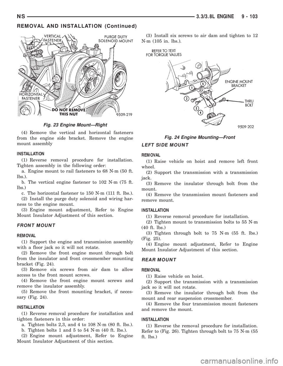
(4) Remove the vertical and horizontal fasteners
from the engine side bracket. Remove the engine
mount assembly
INSTALLATION
(1) Reverse removal procedure for installation.
Tighten assembly in the following order:
a. Engine mount to rail fasteners to 68 N´m (50 ft.
lbs.).
b. The vertical engine fastener to 102 N´m (75 ft.
lbs.)
c. The horizontal fastener to 150 N´m (111 ft. lbs.).
(2) Install the purge duty solenoid and wiring har-
ness to the engine mount.
(3) Engine mount adjustment, Refer to Engine
Mount Insulator Adjustment of this section.
FRONT MOUNT
REMOVAL
(1) Support the engine and transmission assembly
with a floor jack so it will not rotate.
(2) Remove the front engine mount through bolt
from the insulator and front crossmember mounting
bracket (Fig. 24).
(3) Remove six screws from air dam to allow
access to the front mount screws.
(4) Remove the front engine mount screws and
remove the insulator assembly.
(5) Remove the front mounting bracket, if neces-
sary (Fig. 24).
INSTALLATION
(1) Reverse removal procedure for installation and
tighten fasteners in this order:
a. Tighten bolts 2,3, and 4 to 108 N´m (80 ft. lbs.).
b. Tighten bolts 1 and 5 to 54 N´m (40 ft. lbs.).
(2) Engine mount adjustment, Refer to Engine
Mount Insulator Adjustment of this section.(3) Install six screws to air dam and tighten to 12
N´m (105 in. lbs.).
LEFT SIDE MOUNT
REMOVAL
(1) Raise vehicle on hoist and remove left front
wheel.
(2) Support the transmission with a transmission
jack.
(3) Remove the insulator through bolt from the
mount.
(4) Remove the transmission mount fasteners and
remove mount.
INSTALLATION
(1) Reverse removal procedure for installation.
(2) Tighten mount to transmission bolts to 55 N´m
(40 ft. lbs.)
(3) Tighten through bolt to 75 N´m (55 ft. lbs.)
(Fig. 25).
(4) Engine mount adjustment, Refer to Engine
Mount Insulator Adjustment of this section.
REAR MOUNT
REMOVAL
(1) Raise vehicle on hoist.
(2) Support the transmission with a transmission
jack so it will not rotate.
(3) Remove the insulator through bolt from the
mount and rear suspension crossmember.
(4) Remove the four transmission mount fasteners
and remove the mount.
INSTALLATION
(1) Reverse the removal procedure for installation.
Refer to (Fig. 26). Tighten through bolt to 75 N´m (55
ft. lbs.)
Fig. 23 Engine MountÐRight
Fig. 24 Engine MountingÐFront
NS3.3/3.8L ENGINE 9 - 103
REMOVAL AND INSTALLATION (Continued)
Page 1154 of 1938
ENGINE MOUNT RUBBER INSULATORS
Insulator location on (right side) is adjustable to
allow right/left drive train adjustment in relation to
drive shaft assembly length.
Check and reposition right engine mount insulator.
See Adjustments in this section. Adjust drive train
position, if required, for the following conditions:
a. Drive shaft distress. See Group 2, Suspension
and Driveshafts.
b. Any front end structural damage (after repair).
c. Insulator replacement.
ENGINE ASSEMBLY
REMOVAL
(1) Perform fuel pressure release procedure. Refer
to group 14 fuel system for procedure. Remove fuel
line to fuel rail.
(2) Disconnect battery.
(3) Remove air cleaner and hoses.
(4) Remove battery cover, battery and battery tray,
with integral vacuum reservoir, from vehicle.
(5) Block off heater hoses to rear heater assembly,
if equipped.
(6) Drain cooling system. Refer to Group 7, Cooling
System for procedure.
(7) Disconnect heater hoses.
(8) Remove fan module and radiator. Refer to
Group 7 Cooling System for procedure.
(9) Disconnect transmission shift linkage.
(10) Disconnect throttle body linkage and vacuum
hoses from throttle body.
(11) Remove accessory drive belts. Refer to Group
7, Accessory Drive Belts located in Cooling System
for procedure.
(12) Remove air conditioning compressor from
engine and set it aside.
(13) Disconnect generator wiring harness and
remove generator.
(14) Hoist vehicle and remove right and left inner
splash shields.
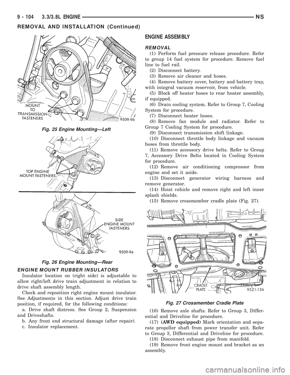
(15) Remove crossmember cradle plate (Fig. 27).
(16) Remove axle shafts. Refer to Group 3, Differ-
ential and Driveline for procedure.
(17)(AWD equipped)Mark orientation and sepa-
rate propeller shaft from power transfer unit. Refer
to Group 3, Differential and Driveline for procedure.
(18) Disconnect exhaust pipe from manifold.
(19) Remove front engine mount and bracket as an
assembly.
Fig. 25 Engine MountingÐLeft
Fig. 26 Engine MountingÐRear
Fig. 27 Crossmember Cradle Plate
9 - 104 3.3/3.8L ENGINENS
REMOVAL AND INSTALLATION (Continued)
Page 1173 of 1938
ADJUSTMENTS
ENGINE MOUNTS
ENGINE MOUNT INSULATOR ADJUSTMENT
(1) Remove the load on the engine motor mounts
by carefully supporting the engine and transmission
assembly with a floor jack.
(2) Loosen the right engine mount insulator verti-
cal fastener and the fore and aft fasteners, and the
front engine mount bracket to front crossmember
screws.
(3) Pry the engine right or left as required to
achieve the proper drive shaft assembly length. Refer
to Group 2, Suspension and Driveshafts for drive-
shaft identification and related assembly length mea-
suring.
(4) Tighten engine mounts and fasteners in the
following order:
(a) Right engine mount insulator vertical bolts
to 102 N´m (75 ft. lbs.) and the fore and aft bolts to
150 N´m (110 ft. lbs.).
(b) Front engine mount screws to 54 N´m (40 ft.
lbs.) the clearance between the snubbers and the
engine should be 2 mm (0.078 inch.) each side.
(c) Left engine mount through bolt to 75 N´m (55
ft. lbs.).
(5) Recheck driveshaft length.
SPECIFICATIONS
3.3/3.8L ENGINE
Type.........................60É V-6 Engine
Bore±3.3L..................93.0 mm (3.66 in.)
Bore±3.8L.................96.0 mm (3.779 in.)
Stroke±3.3L...............81.0 mm (3.188 in.)
Stroke±3.8L...............87.0 mm (3.425 in.)
Compression Ratio±3.3L.................8.9:1
Compression Ratio±3.8L.................9.6:1
Displacement±3.3L..........3.3L (201 Cubic in.)
Displacement±3.8L..........3.8L (231 Cubic in.)
Brake Horsepower±3.3L........158 @ 4850 RPM
Brake Horsepower±3.8L........180 @ 4400 RPM
Torque±3.3L............203 lb. ft. @ 3600 RPM
Torque±3.8L............240 lb. ft. @ 3600 RPM
Firing Order....................1±2±3±4±5±6
Compression Pressure.Refer to Engine Performance
in Standard Service Procedures.
Cylinder Number (Front to Rear)
Front Bank...........................2,4,6
Rear Bank............................1,3,6
Cylinder Block
Cylinder Bore (Standard)±3.3L.........93.0 mm
(3.66 in.)
Cylinder Bore (Standard)±3.8L.........96.0 mm
(3.779 in.)
Out-of-Round (Max.)........0.076 mm (0.003 in.)
Taper (Max.)..............0.051 mm (0.002 in.)
Cylinder Bore Oversize (Max.).........0.508 mm
(0.020 in.)
Tappet Bore Diameter.....22.9896 - 23.0099 mm
(0.9051 - 0.9059 in.)
Pistons
Type Material.......Aluminum Alloy Tin Coated
Clearance at Size Location......0.025 - 0.057 mm
(0.001 - 0.0022 in.)
Weight (Standard Only)±3.3L......38165 grams
(13.439460.1764 oz.)
Weight (Standard Only)±3.8L......43865 grams
(15.450160.1764 oz.)
Pistons for Service..............Standard Only
Piston Pins
Type .......................Press Fit in Rod
(Serviced as an Assembly)
Diameter.........................22.88 mm
(0.9009 - 0.9007 in.)
Length±3.3L................67.25 - 67.75 mm
(2.648 - 2.667 in.)
Lenth±3.8L.................71.25 - 71.75 mm
(2.805 - 2.824 in.)
Clearance in Piston @ 70É......0.006 - 0.019 mm
(0.0002 - 0.0007 in.)
Clearance in Rod................(Interference)
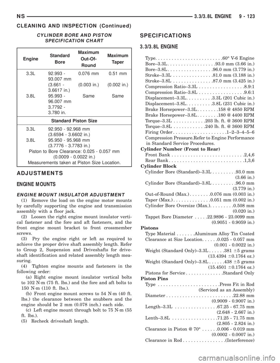
CYLINDER BORE AND PISTON
SPECIFICATION CHART
EngineStandard
BoreMaximum
Out-Of-
RoundMaximum
Taper
3.3L 92.993 -
93.007 mm0.076 mm 0.51 mm
(3.661 -
3.6617 in.)(0.003 in.) (0.002 in.)
3.8L 95.993 -
96.007 mmSame Same
3.7792 -
3.780 in.
Standard Piston Size
3.3L 92.950 - 92.968 mm
(3.6594 - 3.6602 in.)
3.8L 95.950 - 95.968 mm
(3.7776 - 3.7783 in.)
Piston to Bore Clearance: 0.025 - 0.057 mm
(0.0009 - 0.0022 in.)
Measurements taken at Piston Size Location.
NS3.3/3.8L ENGINE 9 - 123
CLEANING AND INSPECTION (Continued)
Page 1232 of 1938
(28) Remove radiator support bolts.It is neces-
sary to loosen the receiver/dryer to gain access
to the radiator bolts.
(29) Remove radiator and fans as an assembly.
(30) Remove accessory drive belt generator/power
steering. Refer to Group 7, for procedure.
(31) Remove both power steering lines at pump,
and cap both lines.
NOTE: It is not necessary to discharge A/C system
for engine removal.
(32) Remove A/C compressor. Secure compressor
away from engine for clearance during engine
removal.
(33) Remove Generator and adjusting bracket.
NOTE: Do not remove the mounting base from the
generator. It is aligned at the factory and cannot be
realigned in the field.
(34) Hoist vehicle.
(35) Remove exhaust pipe at turbo outlet.
(36) Remove connections at starter.
(37) Remove power steering high pressure line
bracket at rear of oil pan.
(38) Remove both driveshafts from transaxle. Refer
to Group 2, Suspension and Driveshafts.
(39) Disconnect clutch cable at transaxle.
(40) Remove reinforcement plate on lower cross-
member.
(41) Remove front and rear engine mounts. Refer
to procedure outlined in this section.
(42) Drain engine oil and remove oil filter if neces-
sary.
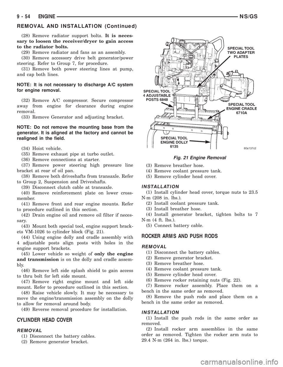
(43) Mount both special tool, engine support brack-
ets VM-1026 to cylinder block (Fig. 21).
(44) Using engine dolly and cradle assembly with
4 adjustable posts align posts with holes in the
engine support brackets.
(45) Lower vehicle so weight ofonly the engine
and transmissionis on the dolly and cradle assem-
bly.
(46) Remove left side splash shield to gain access
to thru bolt for left side mount.
(47) Remove right engine mount and left side
mount. Refer to procedure outlined in this section.
(48) Raise vehicle slowly. It may be necessary to
move the engine/transmission assembly on the dolly
to allow for removal around body.
(49) Reverse removal procedure for installation.
CYLINDER HEAD COVER
REMOVAL
(1) Disconnect the battery cables.
(2) Remove generator bracket.(3) Remove breather hose.
(4) Remove coolant pressure tank.
(5) Remove cylinder head cover.
INSTALLATION
(1) Install cylinder head cover, torque nuts to 23.5
N´m (208 in. lbs.).
(2) Install coolant pressure tank.
(3) Install breather hose.
(4) Install generator bracket, tighten bolts to 7
N´m (4 ft. lbs.).
(5) Connect battery cable.
ROCKER ARMS AND PUSH RODS
REMOVAL
(1) Disconnect the battery cables.
(2) Remove generator bracket.
(3) Remove breather hose.
(4) Remove coolant pressure tank.
(5) Remove cylinder head cover.
(6) Remove rocker retaining nuts (Fig. 22).
(7) Remove rocker assembly. Place them on a
bench in the same order as removed.
(8) Remove the push rods and place them on a
bench in the same order as removed.
INSTALLATION
(1) Install the push rods in the same order as
removed.
(2) Install rocker arm assemblies in the same
order as removed. Tighten the rocker arm nuts to
29.4 N´m (264 in. lbs.) torque.
Fig. 21 Engine Removal
9 - 54 ENGINENS/GS
REMOVAL AND INSTALLATION (Continued)
Page 1283 of 1938
FRAME
INDEX
page page
REMOVAL AND INSTALLATION
FRONT CROSSMEMBER MOUNT BUSHINGS . . . 5
FRONT CROSSMEMBER................... 3SPECIFICATIONS
FRAME AND BODY OPENING DIMENSIONS.... 5
REMOVAL AND INSTALLATION
FRONT CROSSMEMBER
The front suspension crossmember must be
installed in the design location to achieve proper
front end suspension alignment. If the crossmember
is removed without applying reference marks on the
frame rails, align the crossmember according to the
dimensions provided in this group.
NOTE: If the caged nuts in the frame rails become
damaged and cannot be reused, a replacement nut
can be obtained through a MoparTParts supplier.
REMOVAL
(1) Disconnect battery negative cable.
(2) Remove steering column lower cover from
instrument panel. Refer to Group 8E, Instrument
Panel and Systems.
(3) Remove knee blocker reinforcement. Refer to
Group 8E, Instrument Panel and Systems.
(4) Position steering so front wheels are straight
ahead.
CAUTION: Do not rotate steering wheel after disen-
gaging lower coupling from steering gear, damage
to airbag clock spring can result.
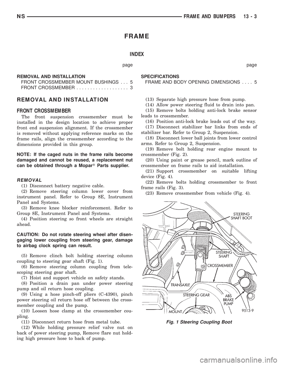
(5) Remove clinch bolt holding steering column
coupling to steering gear shaft (Fig. 1).
(6) Remove steering column coupling from tele-
scoping steering gear shaft.
(7) Hoist and support vehicle on safety stands.
(8) Position a drain pan under power steering
pump and oil return hose coupling.
(9) Using a hose pinch-off pliers (C-4390), pinch
power steering oil return hose off between the cross-
member coupling and the pump.
(10) Loosen hose clamp at the crossmember cou-
pling.
(11) Disconnect return hose from metal tube.
(12) While holding pressure relief valve nut on
back of power steering pump, Remove flare nut hold-
ing high pressure hose to back of pump.(13) Separate high pressure hose from pump.
(14) Allow power steering fluid to drain into pan.
(15) Remove bolts holding anti-lock brake sensor
leads to crossmember.
(16) Position anti-lock brake leads out of the way.
(17) Disconnect stabilizer bar links from ends of
stabilizer bar. Refer to Group 2, Suspension.
(18) Disconnect lower ball joints from lower control
arms. Refer to Group 2, Suspension.
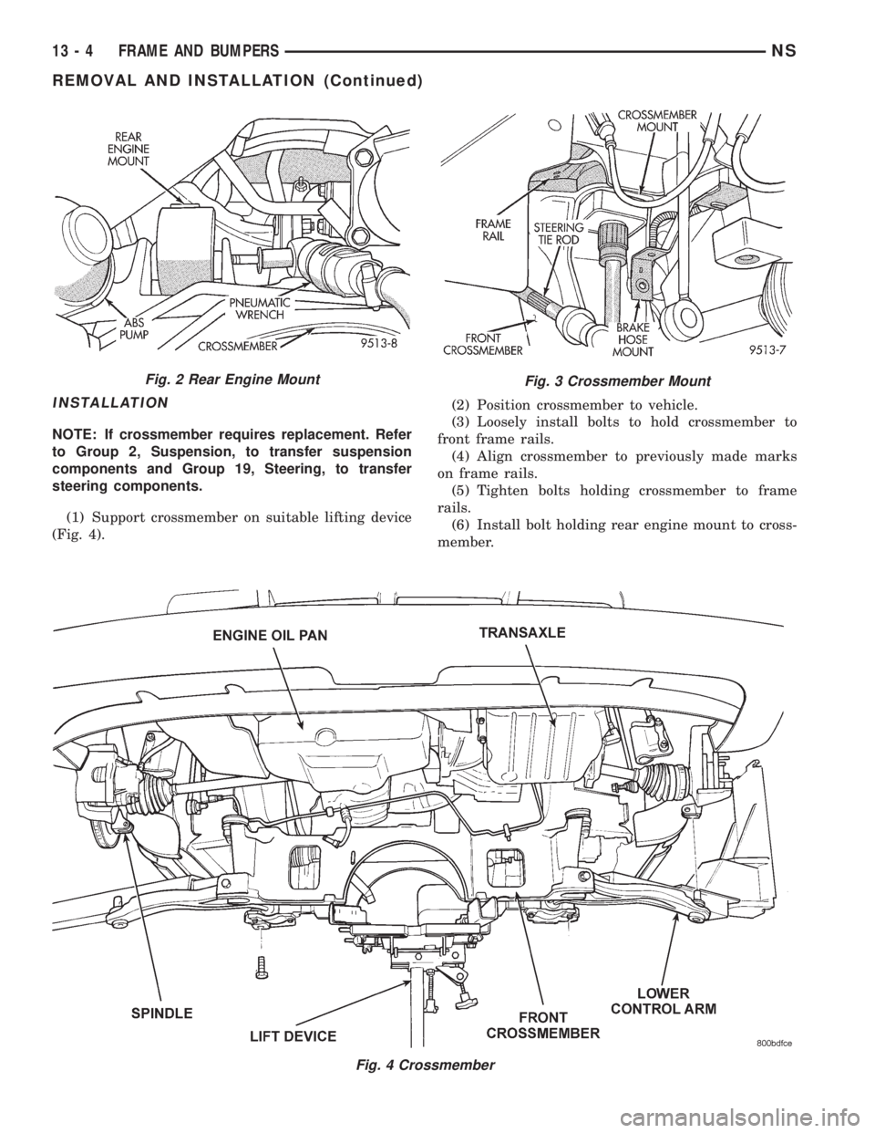
(19) Remove bolt holding rear engine mount to
crossmember (Fig. 2).
(20) Using paint or grease pencil, mark outline of
crossmember on frame rails to aid installation.
(21) Support crossmember on suitable lifting
device (Fig. 4).
(22) Remove bolts holding crossmember to front
frame rails (Fig. 3).
(23) Remove crossmember from vehicle (Fig. 4).
Fig. 1 Steering Coupling Boot
NSFRAME AND BUMPERS 13 - 3
Page 1284 of 1938
INSTALLATION
NOTE: If crossmember requires replacement. Refer
to Group 2, Suspension, to transfer suspension
components and Group 19, Steering, to transfer
steering components.
(1) Support crossmember on suitable lifting device
(Fig. 4).(2) Position crossmember to vehicle.
(3) Loosely install bolts to hold crossmember to
front frame rails.
(4) Align crossmember to previously made marks
on frame rails.
(5) Tighten bolts holding crossmember to frame
rails.
(6) Install bolt holding rear engine mount to cross-
member.
Fig. 4 Crossmember
Fig. 2 Rear Engine MountFig. 3 Crossmember Mount
13 - 4 FRAME AND BUMPERSNS
REMOVAL AND INSTALLATION (Continued)
Page 1285 of 1938
(7) Connect lower ball joints to lower control arms.
Refer to Group 2, Suspension.
(8) Connect stabilizer bar links to ends of stabi-
lizer bar. Refer to Group 2, Suspension.
(9) Install bolts to hold anti-lock brake sensor
leads to crossmember.
(10) Install high pressure hose to pump.
(11) Connect return hose to metal tube.
(12) Tighten hose clamp at the crossmember cou-
pling.
(13) Remove pinch-off pliers.
(14) Position steering so front wheels are straight
ahead.
(15) Install steering column coupling to telescoping
steering gear shaft.
(16) Install clinch bolt to hold steering column cou-
pling to steering gear shaft.
(17) Install knee blocker reinforcement. Refer to
Group 8E, Instrument Panel and Systems.
(18) Install steering column lower cover from
instrument panel. Refer to Group 8E, Instrument
Panel and Systems.
(19) Connect battery negative cable.
FRONT CROSSMEMBER MOUNT BUSHINGS
REMOVAL
(1) Using paint or grease pencil, mark outline of
crossmember on frame rails.
(2) Loosen bolts holding crossmember to frame
rails.
(3) Remove bolt on bushing that requires replace-
ment.
(4) Allow crossmember to drop down enough to
gain clearance for bushing removal.
(5) Remove bushing from vehicle.
INSTALLATION
(1) Apply rubber lube or soap to replacement bush-
ing.(2) Insert lower half of bushing into square hole in
crossmember.
(3) Place upper half of bushing on top of cross-
member aligned to receive square tube protruding
upward from lower bushing half.
(4) Squeeze bushing halves together to ensure they
are properly mated.
(5) Lift crossmember upward to close gap between
the bushing and frame.
(6) Verify that lower bushing is fully seated into
crossmember and upper bushing.
(7) Install bolt to hold bushing and crossmember
to frame rail hand tight.
(8) Align crossmember to reference marks on
frame rails.
(9) Tighten crossmember to frame rails attaching
bolts to 163 N´m (120 ft. lbs.) torque.
SPECIFICATIONS
FRAME AND BODY OPENING DIMENSIONS
Frame dimensions are listed in metric scale. All
dimensions are from center to center of Principal
Locating Point (PLP), or from center to center of PLP
and fastener location.
VEHICLE PREPARATION
Position the vehicle on a frame alignment rack,
refer to instructions provided with equipment being
used. Adjust the vehicle PLP heights to the specified
dimension above the work surface (datum line). Ver-
tical dimensions can be taken from the datum line to
the locations indicated were applicable. Refer to (Fig.
5), (Fig. 6), (Fig. 7), (Fig. 8), (Fig. 9), (Fig. 10) and
(Fig. 11) for proper dimensions.
NSFRAME AND BUMPERS 13 - 5
REMOVAL AND INSTALLATION (Continued)