1996 CHRYSLER VOYAGER suspension
[x] Cancel search: suspensionPage 1457 of 1938
CAUTION: Proper torque on the cradle plate to
suspension cradle mounting bolts is very impor-
tant.
(8) Install cradle plate on front suspension cradle
and install the 10 cradle plate to cradle attaching
bolts and nuts (Fig. 8). Tighten all attaching bolts to
a torque of 165 N´m (123 ft. lbs.).
(9) Install the bracket (Fig. 9) attaching the power
steering fluid tubes to the front suspension cradle.
CAUTION:
(10) Install the power steering fluid return hose on
the steel tube at the front suspension cradle (Fig. 4).
(11) Install a screw type hose clamp on the power
steering hose to steel tube connection.Be sure hose
clamp is installed on return tube past the upset
bead on the tube.Tighten the screw clamp to a
torque of 2 N´m (18 in. lbs.).
CAUTION: The protective heat shield sleeves must
cover the entire rubber hose and hose to tube con-
nection portion of both the power steering fluid
pressure and return hoses (Fig. 4). This is required
to prevent the power steering hoses from being
overheated.
(12) When used, properly position the protective
heat sleeves on the power steering hoses. Then, tie
strap the heat sleeves to the power steering hoses to
keep them in their proper position.
(13) Install the front tire and wheel assemblies on
vehicle. Install the wheel lug nuts and torque to 129
N´m (95 ft. lbs.).
(14) Lower the vehicle to a level were the interior
of vehicle is accessible.
(15) Using the intermediate coupler, turn the front
wheels of the vehicle to the left until the intermedi-
ate coupler shaft is properly aligned with the steer-
ing column coupler. Assemble the steering column
shaft coupler (Fig. 3) onto the steering gear interme-
diate coupler. Install steering column coupler to
intermediate shaft retaining pinch bolt (Fig. 3).
Tighten the pinch bolt nut to a torque of 28 N´m (250
in. lbs.).
CAUTION: Do not use automatic transmission fluid
in the power steering system. Only use Mopar,
Power Steering Fluid or an exact equivalent prod-
uct.
(16) Fill power steering pump fluid reservoir to the
proper level.
(17) Start the engine and let run for a few seconds.
Then turn the engine off.(18) Add fluid if necessary. Repeat the above pro-
cedure until the fluid level remains constant after
running the engine.
(19) Raise front wheels of vehicle off the ground.
(20) Start the engine. Slowly turn the steering
wheel right and left, lightly contacting the wheel
stops. Then turn the engine off.
(21) Add power steering fluid if necessary.
(22) Lower the vehicle and turn the steering wheel
slowly from lock to lock.
(23) Stop the engine. Check the fluid level and
refill as required.
(24) If the fluid is extremely foamy, allow the vehi-
cle to stand a few minutes and repeat the above pro-
cedure.
(25) Fill power steering reservoir to correct level
with Mopart, Power Steering Fluid, or equivalent.
(26) Adjust toe (Refer to Group 2 Suspension).
DISASSEMBLY AND ASSEMBLY
STEERING GEAR INNER TIE ROD BOOT
DISASSEMBLE
NOTE: The removal and installation of the inner tie
rod boot must be performed with the steering gear
assembly removed from the vehicle.
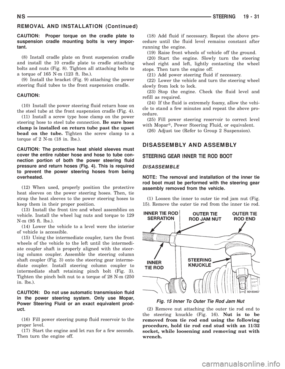
(1) Loosen the inner to outer tie rod jam nut (Fig.
15). Remove the outer tie rod from the inner tie rod.
(2) Remove nut attaching the outer tie rod end to
the steering knuckle (Fig. 16).Nut is to be
removed from tie rod end using the following
procedure, hold tie rod end stud with an 11/32
socket, while loosening and removing nut with
wrench.
Fig. 15 Inner To Outer Tie Rod Jam Nut
NSSTEERING 19 - 31
REMOVAL AND INSTALLATION (Continued)
Page 1459 of 1938
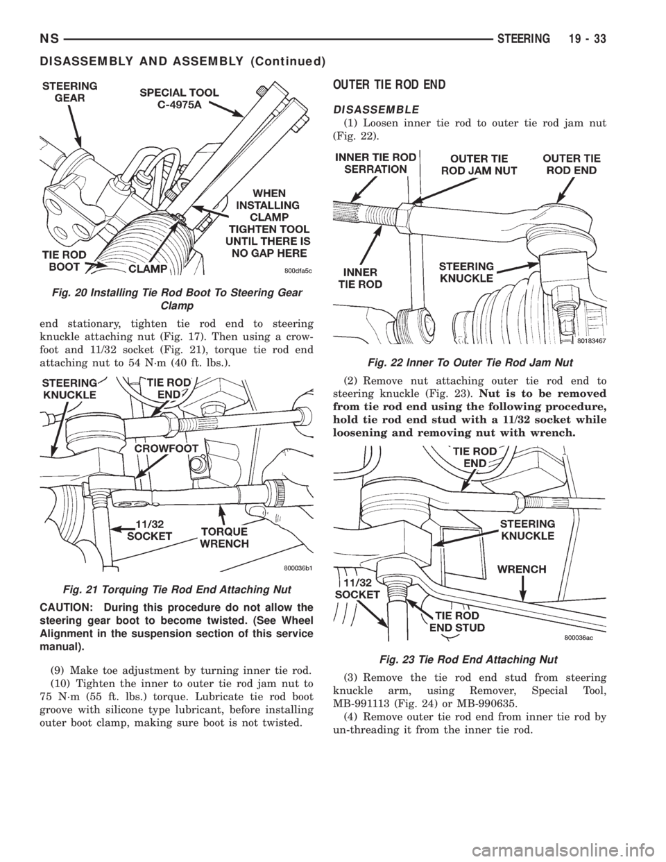
end stationary, tighten tie rod end to steering
knuckle attaching nut (Fig. 17). Then using a crow-
foot and 11/32 socket (Fig. 21), torque tie rod end
attaching nut to 54 N´m (40 ft. lbs.).
CAUTION: During this procedure do not allow the
steering gear boot to become twisted. (See Wheel
Alignment in the suspension section of this service
manual).
(9) Make toe adjustment by turning inner tie rod.
(10) Tighten the inner to outer tie rod jam nut to
75 N´m (55 ft. lbs.) torque. Lubricate tie rod boot
groove with silicone type lubricant, before installing
outer boot clamp, making sure boot is not twisted.
OUTER TIE ROD END
DISASSEMBLE
(1) Loosen inner tie rod to outer tie rod jam nut
(Fig. 22).
(2) Remove nut attaching outer tie rod end to
steering knuckle (Fig. 23).Nut is to be removed
from tie rod end using the following procedure,
hold tie rod end stud with a 11/32 socket while
loosening and removing nut with wrench.
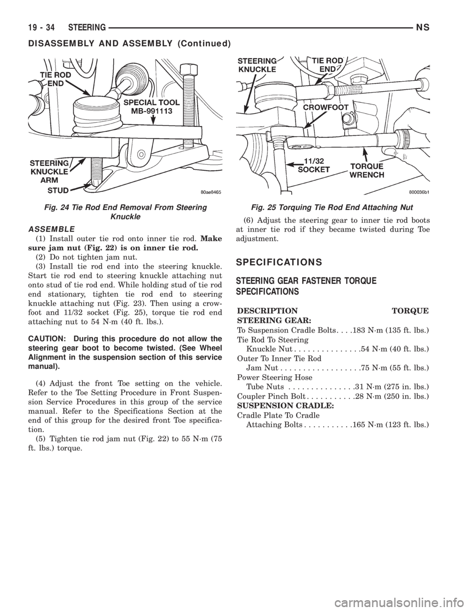
(3) Remove the tie rod end stud from steering
knuckle arm, using Remover, Special Tool,
MB-991113 (Fig. 24) or MB-990635.
(4) Remove outer tie rod end from inner tie rod by
un-threading it from the inner tie rod.
Fig. 20 Installing Tie Rod Boot To Steering Gear
Clamp
Fig. 21 Torquing Tie Rod End Attaching Nut
Fig. 22 Inner To Outer Tie Rod Jam Nut
Fig. 23 Tie Rod End Attaching Nut
NSSTEERING 19 - 33
DISASSEMBLY AND ASSEMBLY (Continued)
Page 1460 of 1938
ASSEMBLE
(1) Install outer tie rod onto inner tie rod.Make
sure jam nut (Fig. 22) is on inner tie rod.
(2) Do not tighten jam nut.
(3) Install tie rod end into the steering knuckle.
Start tie rod end to steering knuckle attaching nut
onto stud of tie rod end. While holding stud of tie rod
end stationary, tighten tie rod end to steering
knuckle attaching nut (Fig. 23). Then using a crow-
foot and 11/32 socket (Fig. 25), torque tie rod end
attaching nut to 54 N´m (40 ft. lbs.).
CAUTION: During this procedure do not allow the
steering gear boot to become twisted. (See Wheel
Alignment in the suspension section of this service
manual).
(4) Adjust the front Toe setting on the vehicle.
Refer to the Toe Setting Procedure in Front Suspen-
sion Service Procedures in this group of the service
manual. Refer to the Specifications Section at the
end of this group for the desired front Toe specifica-
tion.
(5) Tighten tie rod jam nut (Fig. 22) to 55 N´m (75
ft. lbs.) torque.(6) Adjust the steering gear to inner tie rod boots
at inner tie rod if they became twisted during Toe
adjustment.
SPECIFICATIONS
STEERING GEAR FASTENER TORQUE
SPECIFICATIONS
DESCRIPTION TORQUE
STEERING GEAR:
To Suspension Cradle Bolts. . . .183 N´m (135 ft. lbs.)
Tie Rod To Steering
Knuckle Nut...............54N´m(40ft.lbs.)
Outer To Inner Tie Rod
JamNut..................75N´m(55ft.lbs.)
Power Steering Hose
Tube Nuts...............31N´m(275 in. lbs.)
Coupler Pinch Bolt...........28N´m(250 in. lbs.)
SUSPENSION CRADLE:
Cradle Plate To Cradle
Attaching Bolts...........165 N´m (123 ft. lbs.)
Fig. 24 Tie Rod End Removal From Steering
KnuckleFig. 25 Torquing Tie Rod End Attaching Nut
19 - 34 STEERINGNS
DISASSEMBLY AND ASSEMBLY (Continued)
Page 1494 of 1938
(5) Continuity should exist only with transaxle in
Reverse position.
(6) No continuity should exist from either pin to
the case.
TRANSAXLE AND TORQUE CONVERTER REMOVAL
NOTE: Transaxle removal does NOT require engine
removal.
The transaxle and torque converter must be
removed as an assembly; otherwise, the torque con-
verter drive plate, pump bushing, or oil seal may be
damaged. The drive plate will not support a load;
therefore, none of the weight of the transaxle should
be allowed to rest on the plate during removal.
REMOVAL
(1) Disconnect negative battery cable.
(2) Remove air cleaner and hoses.
(3) Disconnect throttle linkage and shift linkage
from transaxle.
(4) Unplug torque converter clutch connector,
located near the dipstick. Unplug the gear position
switch.
(5) Remove transaxle dipstick tube.
(6) Remove the transaxle cooler lines and plug.
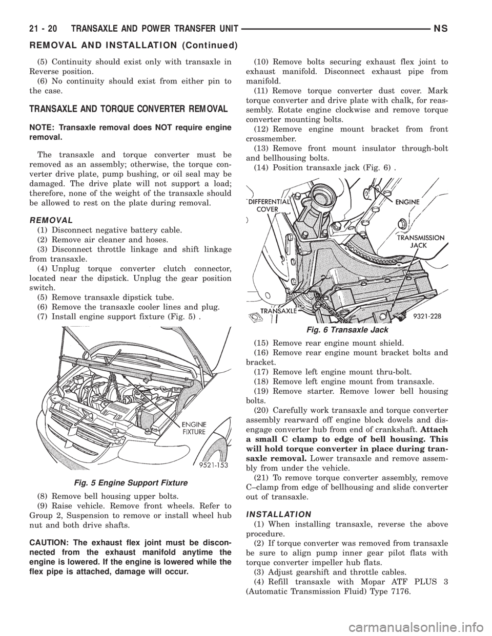
(7) Install engine support fixture (Fig. 5) .
(8) Remove bell housing upper bolts.
(9) Raise vehicle. Remove front wheels. Refer to
Group 2, Suspension to remove or install wheel hub
nut and both drive shafts.
CAUTION: The exhaust flex joint must be discon-
nected from the exhaust manifold anytime the
engine is lowered. If the engine is lowered while the
flex pipe is attached, damage will occur.(10) Remove bolts securing exhaust flex joint to
exhaust manifold. Disconnect exhaust pipe from
manifold.
(11) Remove torque converter dust cover. Mark
torque converter and drive plate with chalk, for reas-
sembly. Rotate engine clockwise and remove torque
converter mounting bolts.
(12) Remove engine mount bracket from front
crossmember.
(13) Remove front mount insulator through-bolt
and bellhousing bolts.
(14) Position transaxle jack (Fig. 6) .
(15) Remove rear engine mount shield.
(16) Remove rear engine mount bracket bolts and
bracket.
(17) Remove left engine mount thru-bolt.
(18) Remove left engine mount from transaxle.
(19) Remove starter. Remove lower bell housing
bolts.
(20) Carefully work transaxle and torque converter
assembly rearward off engine block dowels and dis-
engage converter hub from end of crankshaft.Attach
a small C clamp to edge of bell housing. This
will hold torque converter in place during tran-
saxle removal.Lower transaxle and remove assem-
bly from under the vehicle.
(21) To remove torque converter assembly, remove
C±clamp from edge of bellhousing and slide converter
out of transaxle.
INSTALLATION
(1) When installing transaxle, reverse the above
procedure.
(2) If torque converter was removed from transaxle
be sure to align pump inner gear pilot flats with
torque converter impeller hub flats.
(3) Adjust gearshift and throttle cables.
(4) Refill transaxle with Mopar ATF PLUS 3
(Automatic Transmission Fluid) Type 7176.
Fig. 5 Engine Support Fixture
Fig. 6 Transaxle Jack
21 - 20 TRANSAXLE AND POWER TRANSFER UNITNS
REMOVAL AND INSTALLATION (Continued)
Page 1564 of 1938
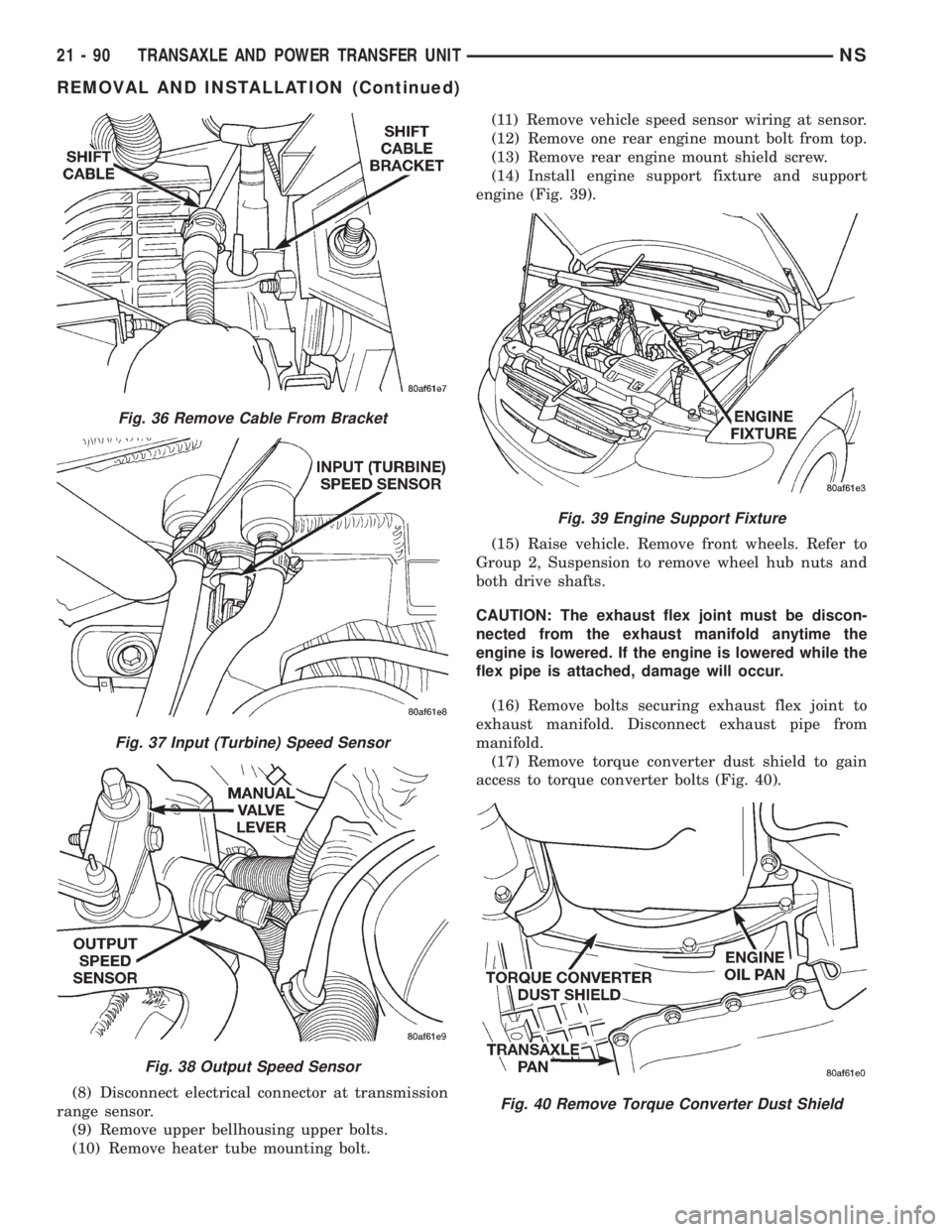
(8) Disconnect electrical connector at transmission
range sensor.
(9) Remove upper bellhousing upper bolts.
(10) Remove heater tube mounting bolt.(11) Remove vehicle speed sensor wiring at sensor.
(12) Remove one rear engine mount bolt from top.
(13) Remove rear engine mount shield screw.
(14) Install engine support fixture and support
engine (Fig. 39).
(15) Raise vehicle. Remove front wheels. Refer to
Group 2, Suspension to remove wheel hub nuts and
both drive shafts.
CAUTION: The exhaust flex joint must be discon-
nected from the exhaust manifold anytime the
engine is lowered. If the engine is lowered while the
flex pipe is attached, damage will occur.
(16) Remove bolts securing exhaust flex joint to
exhaust manifold. Disconnect exhaust pipe from
manifold.
(17) Remove torque converter dust shield to gain
access to torque converter bolts (Fig. 40).
Fig. 36 Remove Cable From Bracket
Fig. 37 Input (Turbine) Speed Sensor
Fig. 38 Output Speed Sensor
Fig. 39 Engine Support Fixture
Fig. 40 Remove Torque Converter Dust Shield
21 - 90 TRANSAXLE AND POWER TRANSFER UNITNS
REMOVAL AND INSTALLATION (Continued)
Page 1642 of 1938
CAUTION: A certain amount of oil will drain out of
the transaxle when the drive shaft is removed.
(2) Remove right front drive shaft. Install a plug
into the right driveshaft seal hole. Refer to Group 2,
Suspension to remove or install wheel hub nut and
right drive shaft.
(3) Mark propeller shaft front flange.
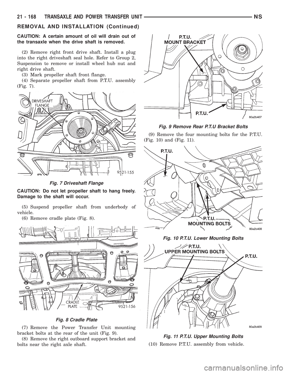
(4) Separate propeller shaft from P.T.U. assembly
(Fig. 7).
CAUTION: Do not let propeller shaft to hang freely.
Damage to the shaft will occur.
(5) Suspend propeller shaft from underbody of
vehicle.
(6) Remove cradle plate (Fig. 8).
(7) Remove the Power Transfer Unit mounting
bracket bolts at the rear of the unit (Fig. 9).
(8) Remove the right outboard support bracket and
bolts near the right axle shaft.(9) Remove the four mounting bolts for the P.T.U.
(Fig. 10) and (Fig. 11).
(10) Remove P.T.U. assembly from vehicle.
Fig. 7 Driveshaft Flange
Fig. 8 Cradle Plate
Fig. 9 Remove Rear P.T.U Bracket Bolts
Fig. 10 P.T.U. Lower Mounting Bolts
Fig. 11 P.T.U. Upper Mounting Bolts
21 - 168 TRANSAXLE AND POWER TRANSFER UNITNS
REMOVAL AND INSTALLATION (Continued)
Page 1721 of 1938
Improper inflation can cause:
²Uneven wear patterns
²Reduced tread life
²Reduced fuel economy
²Unsatisfactory ride
²The vehicle to drift.
Proper tire air inflation pressure specifications can
be found on the Vehicle Tire Placard provided with
the vehicle. See owner's manual.
Tire pressures have been chosen to provide safe
operation, vehicle stability, and a smooth ride. Tire
pressure should be checked cold once per month.
Check tire pressure more frequently when the
weather temperature varies widely. Tire pressure will
decrease when the outdoor temperature drops.
Tire inflation pressures specified on the placard
are always cold inflation pressure. Cold inflation
pressure is obtained after the vehicle has not been
operated for at least 3 hours, or the vehicle is driven
less than one mile after being inoperative for 3
hours. Tire inflation pressures may increase from 2
to 6 pounds per square inch (psi) during operation.
Do not reduce this normal pressure build-up.
TIRE PRESSURE FOR HIGH-SPEED DRIVING
Chrysler Corporation advocates driving at safe
speeds within posted speed limits. Where speed lim-
its allow the vehicle to be driven at high speeds, cor-
rect tire inflation pressure is very important. For
speeds up to and including 75 mph (120 km/h), tires
must be inflated to the pressures shown on the tire
placard.
Vehicles loaded to the maximum capacity should
not be driven at speeds above 75 mph (120 km/h).
For emergency vehicles that are driven at speeds
over 90 mph (144 km/h), special high-speed tires
must be used. Consult tire manufacturer for correct
inflation pressure recommendations.
REPLACEMENT TIRES
The original equipment tires provide a proper bal-
ance of many characteristics such as:
²Ride
²Noise
²Handling
²Durability
²Tread life
²Traction
²Rolling resistance
²Speed capability
It is recommend that tires equivalent to the origi-
nal equipment tires be used when replacement is
needed.
Failure to use equivalent replacement tires may
adversely affect the safety and handling of the vehicle.
The use of oversize tires not listed in the specifica-
tion charts may cause interference with vehicle com-
ponents. Under extremes of suspension and steering
travel, interference with vehicle components may
cause tire damage.
WARNING: FAILURE TO EQUIP THE VEHICLE WITH
TIRES HAVING ADEQUATE SPEED CAPABILITY
CAN RESULT IN SUDDEN TIRE FAILURE.
DIAGNOSIS AND TESTING
PRESSURE GAUGES
A quality air pressure gauge is recommended to
check tire pressure. After checking the air pressure,
replace valve cap finger tight.
TREAD WEAR INDICATORS
Tread wear indicators are molded into the bottom
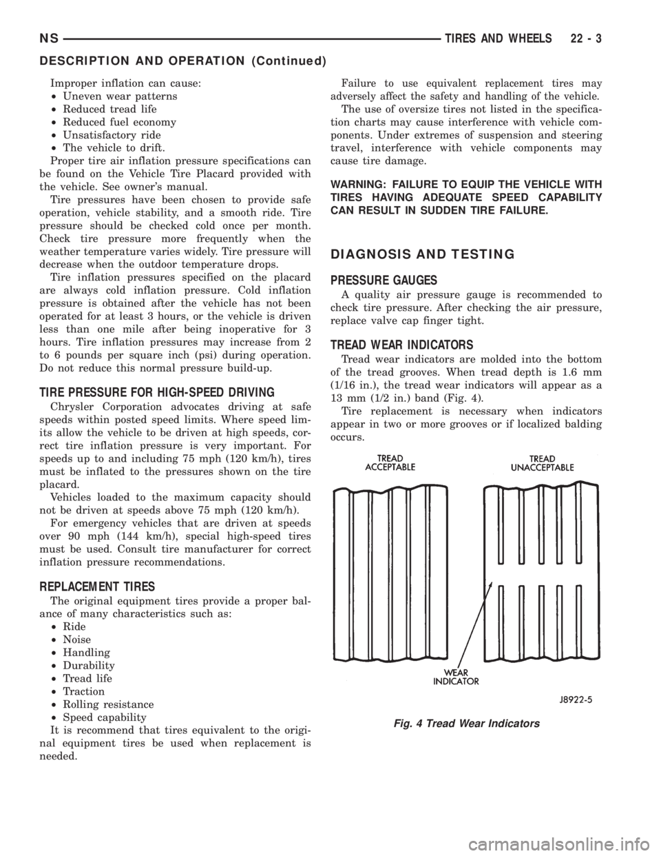
of the tread grooves. When tread depth is 1.6 mm
(1/16 in.), the tread wear indicators will appear as a
13 mm (1/2 in.) band (Fig. 4).
Tire replacement is necessary when indicators
appear in two or more grooves or if localized balding
occurs.
Fig. 4 Tread Wear Indicators
NSTIRES AND WHEELS 22 - 3
DESCRIPTION AND OPERATION (Continued)
Page 1767 of 1938
INSTALLATION
(1) Insert front guide rail through front access
hole.
(2) Insert rear guide rail through rear access hole.
(3) Place window regulator in position on inner
door panel.
(4) Place screw heads on guide rails in position
through key hole slots in inner door panel.
(5) Tighten screws to attach front and rear guide
rails to inner door panel.
(6) Connect wire connector into power window
motor, if equipped.
(7) Install door glass.
(8) Verify door glass alignment and operation.
(9) Install water shield and door trim panel.
FRONT SEAT
REMOVAL
(1) From under vehicle, remove nuts attaching
front seat risers to the floor.
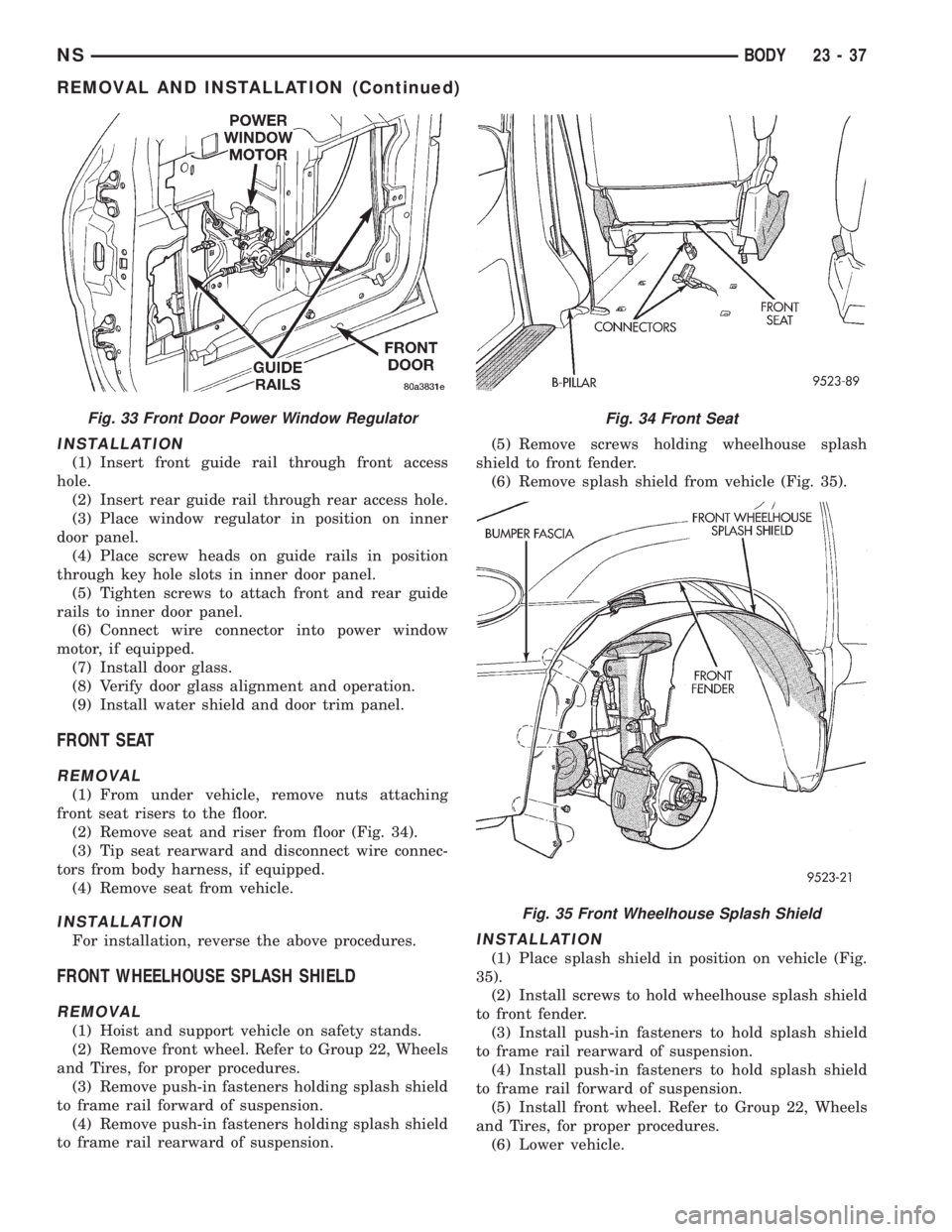
(2) Remove seat and riser from floor (Fig. 34).
(3) Tip seat rearward and disconnect wire connec-
tors from body harness, if equipped.
(4) Remove seat from vehicle.
INSTALLATION
For installation, reverse the above procedures.
FRONT WHEELHOUSE SPLASH SHIELD
REMOVAL
(1) Hoist and support vehicle on safety stands.
(2) Remove front wheel. Refer to Group 22, Wheels
and Tires, for proper procedures.
(3) Remove push-in fasteners holding splash shield
to frame rail forward of suspension.
(4) Remove push-in fasteners holding splash shield
to frame rail rearward of suspension.(5) Remove screws holding wheelhouse splash
shield to front fender.
(6) Remove splash shield from vehicle (Fig. 35).
INSTALLATION
(1) Place splash shield in position on vehicle (Fig.
35).
(2) Install screws to hold wheelhouse splash shield
to front fender.
(3) Install push-in fasteners to hold splash shield
to frame rail rearward of suspension.
(4) Install push-in fasteners to hold splash shield
to frame rail forward of suspension.
(5) Install front wheel. Refer to Group 22, Wheels
and Tires, for proper procedures.
(6) Lower vehicle.
Fig. 33 Front Door Power Window RegulatorFig. 34 Front Seat
Fig. 35 Front Wheelhouse Splash Shield
NSBODY 23 - 37
REMOVAL AND INSTALLATION (Continued)