Page 1761 of 1954

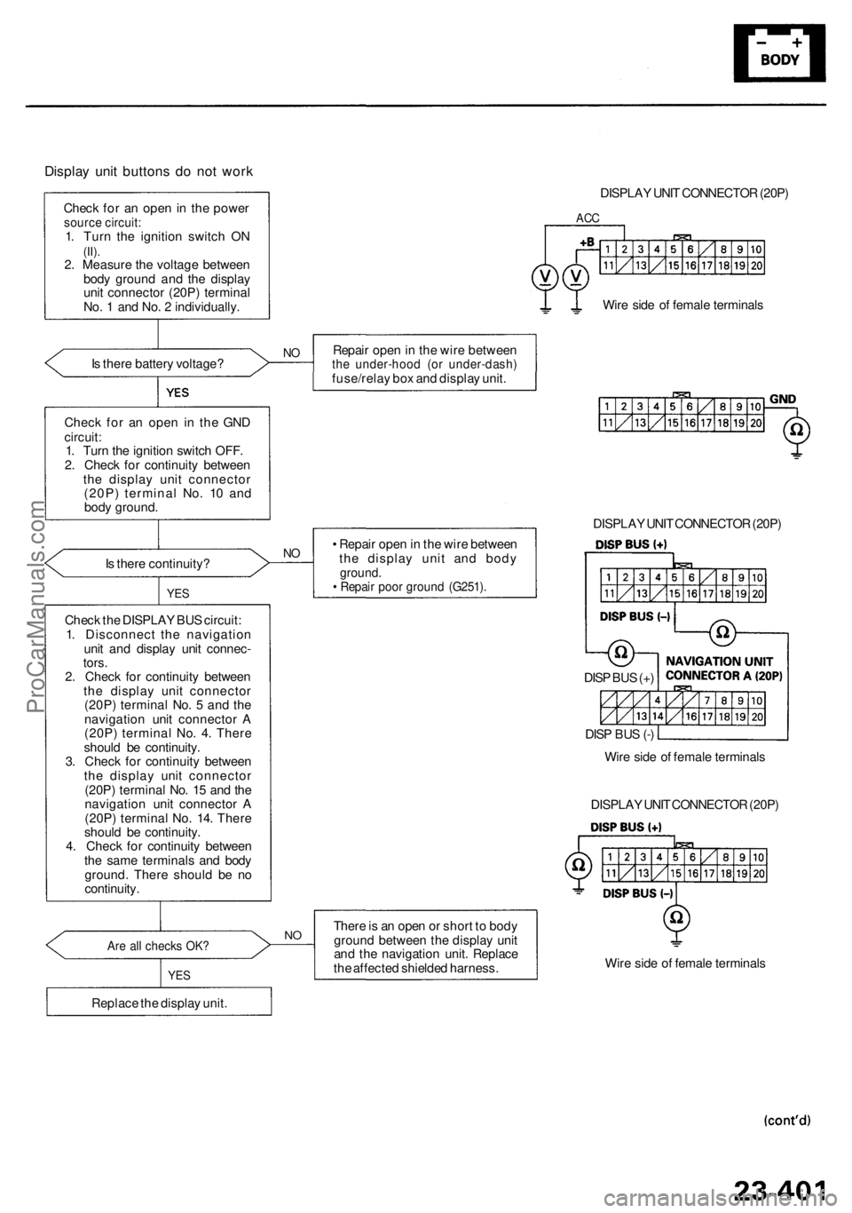
Display uni t button s d o no t wor k
Chec k fo r a n ope n in th e powe rsource circuit :1. Tur n th e ignitio n switc h O N(II).2. Measur e th e voltag e betwee n
bod y groun d an d th e displa y
uni t connecto r (20P ) termina l
No . 1 an d No . 2 individually .
I s ther e batter y voltage ?
NORepai r ope n in th e wir e betwee nthe under-hoo d (o r under-dash )fuse/relay bo x an d displa y unit .
Chec k fo r a n ope n i n th e GN D
circuit :1. Tur n th e ignitio n switc h OFF .
2 . Chec k fo r continuit y betwee n
th e displa y uni t connecto r
(20P ) termina l No . 1 0 an d
bod y ground .
I s ther e continuity ?
NO• Repai r ope n in th e wir e betwee n
th e displa y uni t an d bod y
ground .• Repai r poo r groun d (G251) .
Check th e DISPLA Y BU S circuit :
1 . Disconnec t th e navigatio n
uni t an d displa y uni t connec -
tors .
2 . Chec k fo r continuit y betwee n
th e displa y uni t connecto r
(20P ) termina l No . 5 an d th e
navigatio n uni t connecto r A
(20P ) termina l No . 4 . Ther e
shoul d b e continuity .
3 . Chec k fo r continuit y betwee n
th e displa y uni t connecto r
(20P ) termina l No . 1 5 an d th e
navigatio n uni t connecto r A
(20P ) termina l No . 14 . Ther e
shoul d b e continuity .
4 . Chec k fo r continuit y betwee n
th e sam e terminal s an d bod y
ground . Ther e shoul d b e n o
continuity .
YES
Are al l check s OK ?
YES
Replac e th e displa y unit .
NOTher e is a n ope n o r shor t t o bod y
groun d betwee n th e displa y uni t
an d th e navigatio n unit . Replac e
th e affecte d shielde d harness . Wir
e sid e o f femal e terminal s
DISPLA
Y UNI T CONNECTO R (20P )
DISPLA
Y UNI T CONNECTO R (20P )
ACC
Wir e sid e o f femal e terminal s
DISPLA Y UNI T CONNECTO R (20P )
Wir e sid e o f femal e terminal s
DIS
P BU S (+ )
DIS P BU S (- )
ProCarManuals.com
Page 1764 of 1954

Troubleshooting
'00 - 0 1 Model s
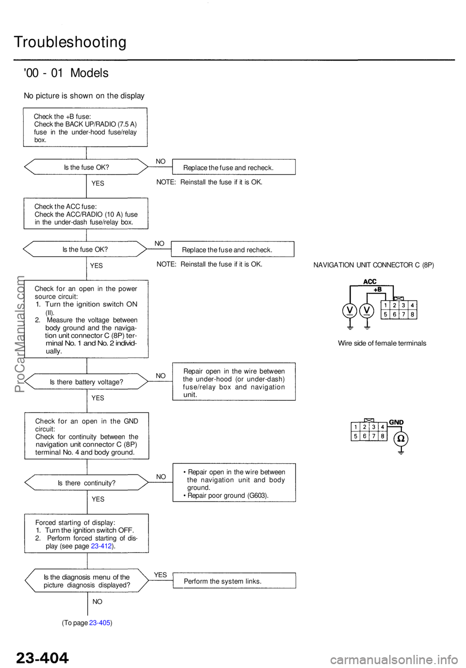
No pictur e is show n o n th e displa y
Check th e + B fuse :
Chec k th e BAC K UP/RADI O (7. 5 A )
fus e i n th e under-hoo d fuse/rela y
box.
Is th e fus e OK ?
Replace th e fus e an d recheck .
NOTE : Reinstal l th e fus e if i t i s OK .NO
YE S
Chec k th e AC C fuse :
Chec k th e ACC/RADI O (1 0 A ) fus e
i n th e under-das h fuse/rela y box .
I s th e fus e OK ?
NOReplac e th e fus e an d recheck .
NOTE : Reinstal l th e fus e if i t i s OK .
YES
Chec k fo r a n ope n i n th e powe r
sourc e circuit :
1. Tur n th e ignitio n switc h O N(II).2. Measur e th e voltag e betwee nbody groun d an d th e naviga -tion uni t connecto r C (8P ) ter -mina l No . 1 an d No . 2 individ -ually.
NAVIGATIO N UNI T CONNECTO R C (8P )
Wire sid e o f femal e terminal s
Is ther e batter y voltage ?NORepai r ope n i n th e wir e betwee n
th e under-hoo d (o r under-dash )
fuse/rela y bo x an d navigatio n
unit.YES
Chec k fo r a n ope n i n th e GN D
circuit :
Chec k fo r continuit y betwee n th e
navigatio n uni t connecto r C (8P )termina l No . 4 an d bod y ground .
Is ther e continuity ?
YES
NO• Repai r ope n in th e wir e betwee n
th e navigatio n uni t an d bod y
ground .
• Repai r poo r groun d (G603) .
Force d startin g o f display :
1. Tur n th e ignitio n switc h OFF .2. Perfor m force d startin g o f dis -
pla y (se e pag e 23-412 ).
Is th e diagnosi s men u o f th epictur e diagnosi s displayed ?
YESPerfor m th e syste m links .
NO
(T o pag e 23-405 )
ProCarManuals.com
Page 1765 of 1954

(From pag e 23-404 )
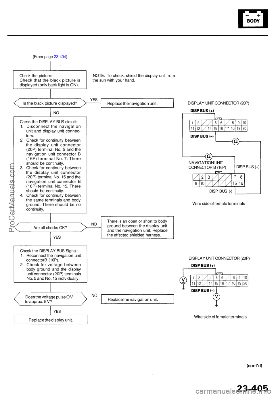
Check th e picture :Check tha t th e blac k pictur e i s
displaye d (onl y bac k ligh t i s ON) . NOTE
: T o check , shiel d th e displa y uni t fro m
th e su n wit h you r hand .
I s th e blac k pictur e displayed ?
YESReplac e th e navigatio n unit .
NO
Chec k th e DISPLA Y BU S circuit :1. Disconnec t th e navigatio n
uni t an d displa y uni t connec -
tors.2. Chec k fo r continuit y betwee n
th e displa y uni t connecto r
(20P ) termina l No . 5 an d th e
navigatio n uni t connecto r B
(16P ) termina l No . 7 . Ther e
shoul d b e continuity .
3 . Chec k fo r continuit y betwee n
th e displa y uni t connecto r
(20P ) termina l No . 1 5 an d th e
navigatio n uni t connecto r B
(16P ) termina l No . 15 . Ther e
shoul d b e continuity .
4 . Chec k fo r continuit y betwee n
th e sam e terminal s an d bod y
ground . Ther e shoul d b e n o
continuity .
Doe s th e voltag e puls e O V
t o approx . 5 V ?
NOReplac e th e navigatio n unit .
YES
Replac e th e displa y unit . Wir
e sid e o f femal e terminal s
DISPLAY UNI T CONNECTO R (20P )
DISPLA Y UNI T CONNECTO R (20P )
Wir e sid e o f femal e terminal s
NAVIGATIO
N UNI T
CONNECTO R B (16P )
DISP BU S (- ) DIS
P BU S (+ )
Ther e is a n ope n o r shor t t o bod ygroun d betwee n th e displa y uni t
an d th e navigatio n unit . Replac e
the affecte d shielde d harness .
Are al l check s OK ?NO
YE S
Chec k th e DISPLA Y BU S Signal :1. Reconnec t th e navigatio n uni tconnector B (16P) .2. Chec k fo r voltag e betwee n
bod y groun d an d th e displa y
uni t connecto r (20P ) terminal s
No. 5 an d No . 1 5 individually .
ProCarManuals.com
Page 1767 of 1954

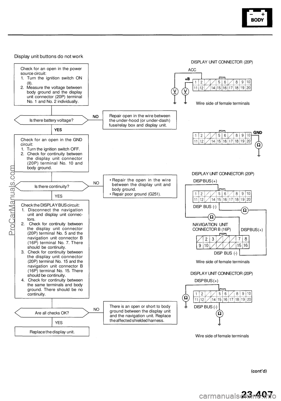
Display uni t button s d o no t wor k
Chec k fo r a n ope n in th e powe r
sourc e circuit :
1 . Tur n th e ignitio n switc h O N
(II).2. Measur e th e voltag e betwee n
bod y groun d an d th e displa y
uni t connecto r (20P ) termina l
No . 1 an d No . 2 individually .
I s ther e batter y voltage ?
Are al l check s OK ?
Repai r ope n in th e wir e betwee n
th e under-hoo d (o r under-dash )
fuse/rela y bo x an d displa y unit .
NO• Repai r th e ope n i n th e wir e
betwee n th e displa y uni t an d
bod y ground .• Repai r poo r groun d (G251) .
Wire sid e o f femal e terminal s
DISPLA Y UNI T CONNECTO R (20P )
DIS P BU S (+ )
Ther e is a n ope n o r shor t t o bod ygroun d betwee n th e displa y uni t
an d th e navigatio n unit . Replac e
th e affecte d shielde d harness .
Chec
k th e DISPLA Y BU S circuit :
1 . Disconnec t th e navigatio n
uni t an d displa y uni t connec -
tors .
2 . Chec k fo r continuit y betwee n
th e displa y uni t connecto r
(20P ) termina l No . 5 an d th e
navigatio n uni t connecto r B
(16P ) termina l No . 7 . Ther e
shoul d b e continuity .
3 . Chec k fo r continuit y betwee n
the displa y uni t connecto r(20P) termina l No . 1 5 an d th e
navigatio n uni t connecto r B
(16P ) termina l No . 15 . Ther e
should b e continuity .4. Chec k fo r continuit y betwee n
th e sam e terminal s an d bod y
ground . Ther e shoul d b e n o
continuity .
Chec
k fo r a n ope n i n th e GN D
circuit :1. Tur n th e ignitio n switc h OFF .
2 . Chec k fo r continuit y betwee n
th e displa y uni t connecto r
(20P ) termina l No . 1 0 an d
bod y ground .
I s ther e continuity ?
YES
Replac e th e displa y unit .
YES
NO
Wir e sid e o f femal e terminal s
DISPLA
Y UNI T CONNECTO R (20P )
DIS P BU S (+ )
DIS P BU S (- )
Wir
e sid e o f femal e terminal s
DISP BU S (- )
NAVIGATIO N UNI TCONNECTO R B (16P )DISP BU S (+)
DIS
P BU S (- )
DISPLA Y UNI T CONNECTO R (20P )
ACC
ProCarManuals.com
Page 1775 of 1954
4. Instal l i n th e revers e orde r o f removal .
Display Uni t
Removal/Installatio n
'96 - 9 9 Model s
1 . Remov e th e displa y unit , audi o uni t an d climat e contro l uni t a s a n assembly .
2 . Remov e th e displa y uni t an d audi o uni t fro m th e frame .
3 . Remov e th e displa y uni t fro m th e audi o unit .
ProCarManuals.com
Page 1776 of 1954
Display Uni t
Removal/Installatio n (cont'd )
'00 - 0 1 Model s
1 . Remov e th e cente r panel , displa y unit , audi o unit , climat e contro l uni t an d bracke t a s a n assembl y (se e sectio n 20 ).
2 . Remov e th e displa y uni t fro m th e bracket .
3. Instal l i n th e revers e orde r o f removal .
ProCarManuals.com