1996 ACURA RL KA9 dashboard
[x] Cancel search: dashboardPage 1371 of 1954
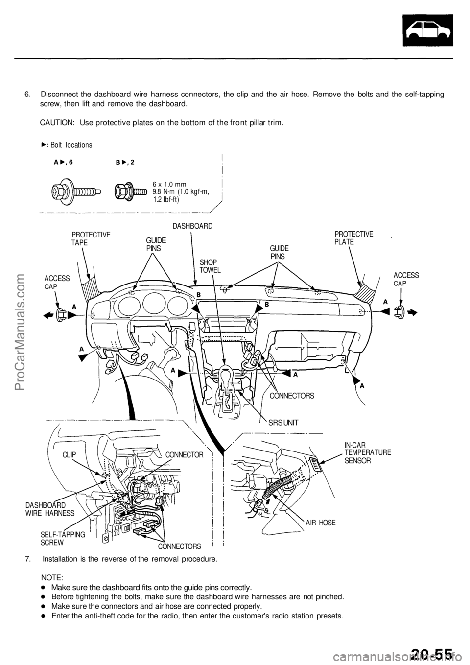
6. Disconnec t th e dashboar d wir e harnes s connectors , th e cli p an d th e ai r hose . Remov e th e bolt s an d th e self-tappin g
screw , the n lif t an d remov e th e dashboard .
CAUTION : Us e protectiv e plate s o n th e botto m of th e fron t pilla r trim .
Bolt location s
PROTECTIV E
TAPE
ACCES SCAP
6 x 1. 0 m m9.8 N- m (1. 0 kgf-m ,
1. 2 Ibf-ft )
DASHBOAR D
GUIDEPINS
PROTECTIV E
PLAT E
ACCESS
CAP
IN-CA R
TEMPERATUR E
SENSOR
7. Installatio n i s th e revers e o f th e remova l procedure .
NOTE:
Make sur e th e dashboar d fit s ont o th e guid e pin s correctly .
Before tightenin g th e bolts , mak e sur e th e dashboar d wir e harnesse s ar e no t pinched .
Mak e sur e th e connector s an d ai r hos e ar e connecte d properly .
Ente r th e anti-thef t cod e fo r th e radio , the n ente r th e customer' s radi o statio n presets .
SELF-TAPPIN G
SCRE W
CONNECTORS AI
R HOS E
CONNECTO
R
CLIP
DASHBOAR D
WIR E HARNES S
SRS UNI T
CONNECTOR S
GUIDEPINSSHO P
TOWE L
ProCarManuals.com
Page 1410 of 1954

Windshield Wipe r Arms/Windshiel d Wipe r Linkag e
Remova l
CAUTION : Pu t o n glove s to protec t you r hands .
NOTE : Tak e car e no t t o scratc h th e hoo d an d body .
1 . Remov e th e windshiel d wipe r arms , the n remov e
th e hoo d sea l an d cow l cover .
INNER CLI P
NOTC H
(Cow l cove r side )
NUTS10 x 1.2 5 mm18 N- m (1. 8 kgf-m ,
1 3 Ibf-ft )
WINDSHIEL D
WIPE R ARM S COW
L
COVE R
2. Remov e th e stru t brac e (se e sectio n 5 ).
3 . Remov e th e contro l bo x cover , the n remov e th e dash -
boar d uppe r cente r reinforcement .
DASHBOARD
UPPE R CENTE R
REINFORCEMEN T
STRU T BRAC E
BRACKE T
6 x 1.0 mm9.8 N-m (1.0 kgf-m ,7.2 Ibf-ft )
STRUT BRACEBRACKE T
8 x 1.2 5 mm22 N- m (2. 2 kgf-m ,16 Ibf-ft )
4. Disconnec t th e connector , detac h th e harnes s clip ,
the n remov e th e windshiel d wipe r linkag e assembly .
WINDSHIEL D
WIPE R LINKAG E
ASSEMBL Y
: Bol t locations , 3
6 x 1. 0 m m9.8 N- m (1. 0 kgf-m ,
7. 2 Ibf-ft )
PIN(Bod y side )
HARNES S
CLIP
5. Separat e th e windshiel d wipe r linkag e an d wind -
shiel d wipe r motor .
NOTE : Whe n installing , alig n th e alignmen t mark s
o n th e lin k an d windshiel d wipe r linkage .
6 x 1. 0 m m8 N- m (0. 8 kgf-m ,
5. 8 Ibf-ft )
ALIGNMEN TMARKSLINK
LIN KWINDSHIEL D
WIPE R LINKAG E
WINDSHIELD WINDSHIEL D
WIPE R LINKAG E WIPE R MOTO R
6. Installatio n is th e revers e o f th e remova l procedure .
NOTE:
Make sur e th e connecto r i s connecte d properly .
I f necessary , replac e an y damage d clips .
Instal l th e windshiel d wipe r arm s properl y a s
describe d o n pag e 20-94 .
Chec k th e windshiel d wipe r moto r operation .
Greas e th e movin g parts .
SHOP
TOWE L
Cli
p location s CONNECTO
R
Bol t locations , 3
NU T10 x 1.2 5 mm18 N- m (1. 8 kgf-m ,
1 3 Ibf-ft )
SPRIN G
WASHE R
ProCarManuals.com
Page 1475 of 1954
In-car Temperatur e Senso r
Replacemen t
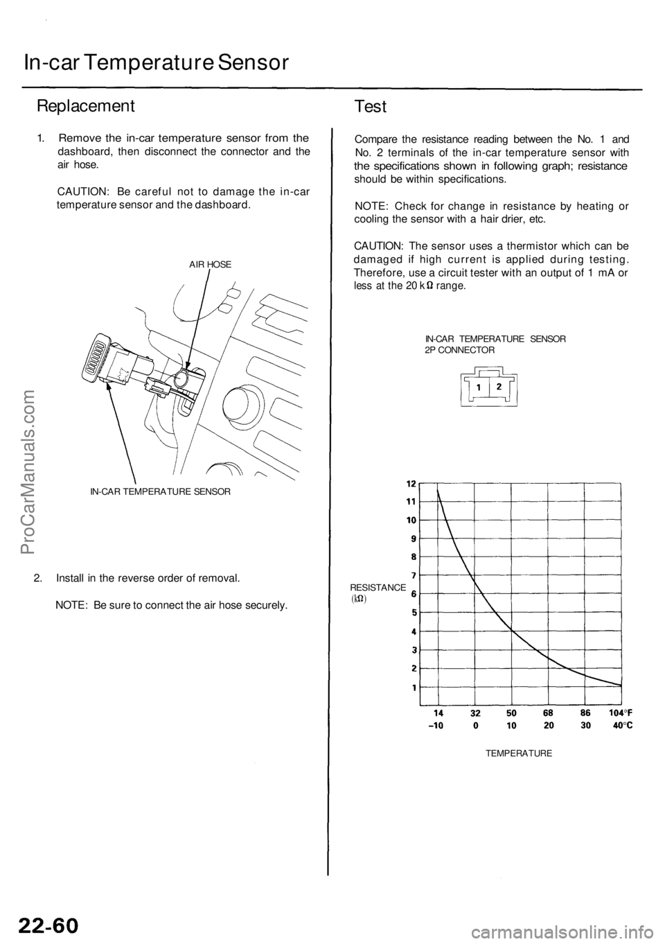
1. Remov e th e in-ca r temperatur e senso r fro m th e
dashboard , the n disconnec t th e connecto r an d th e
ai r hose .
CAUTION : B e carefu l no t t o damag e th e in-ca r
temperatur e senso r an d th e dashboard .
AIR HOS E
IN-CA R TEMPERATUR E SENSO R
2. Instal l i n th e revers e orde r o f removal .
NOTE : B e sur e to connec t th e ai r hos e securely .
Test
Compar e th e resistanc e readin g betwee n th e No . 1 an d
No . 2 terminal s o f th e in-ca r temperatur e senso r wit h
the specification s show n i n followin g graph ; resistanc e
should b e withi n specifications .
NOTE : Chec k fo r chang e i n resistanc e b y heatin g o r
coolin g th e senso r wit h a hai r drier , etc .
CAUTION : Th e senso r use s a thermisto r whic h ca n b e
damage d i f hig h curren t i s applie d durin g testing .
Therefore , us e a circui t teste r wit h a n outpu t o f 1 m A o r
les s a t th e 2 0 k range .
IN-CAR TEMPERATUR E SENSO R
2 P CONNECTO R
RESISTANC E
(k )
TEMPERATUR E
ProCarManuals.com
Page 1477 of 1954
Sunlight Senso r
Replacemen t
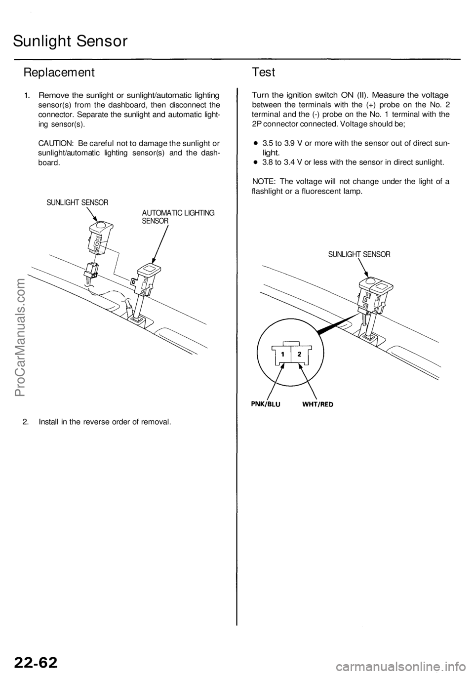
Remove th e sunligh t o r sunlight/automati c lightin g
sensor(s ) fro m th e dashboard , the n disconnec t th e
connector . Separat e th e sunligh t an d automati c light -
ing sensor(s) .
CAUTION: B e carefu l no t t o damag e th e sunligh t o r
sunlight/automati c lightin g sensor(s ) an d th e dash -
board .
SUNLIGH T SENSO R
AUTOMATI C LIGHTIN GSENSOR
2. Instal l i n th e revers e orde r o f removal .
Test
Turn th e ignitio n switc h O N (II) . Measur e th e voltag e
betwee n th e terminal s wit h th e (+ ) prob e o n th e No . 2
termina l an d th e (- ) prob e o n th e No . 1 termina l wit h th e
2 P connecto r connected . Voltag e shoul d be ;
3. 5 to 3. 9 V or mor e wit h th e senso r ou t o f direc t sun -
light.
3.8 to 3. 4 V or les s wit h th e senso r i n direc t sunlight .
NOTE : Th e voltag e wil l no t chang e unde r th e ligh t o f a
flashligh t o r a fluorescen t lamp .
SUNLIGH T SENSO R
ProCarManuals.com
Page 1541 of 1954
BLK/YEL
YEL/BLK
BLU/RE D
BLK
WHT/YE L
GRN/BLU
GRN/YE L
RED/GR N
Ignition switc h O N (II )
Unde r al l condition s
Under al l condition s
Under al l condition s
Driver' s doo r ope n
Combinatio n ligh t
switc h O N
(Excep t "AUTO" )
Unde r al l condition sChec
k fo r voltag e to ground :
Ther e shoul d b e batter y voltage .
Chec k fo r voltag e to ground:
Ther e shoul d b e batter y voltage .
Check fo r continuit y to ground :
There shoul d b e continuity .
Chec k fo r voltag e to ground :
There shoul d b e batter y voltage .
Check fo r voltag e t o ground :
Ther e shoul d b e 1 V or less .
Chec k fo r continuit y t o ground :
Ther e shoul d b e continuity .
Chec k fo r voltag e to ground :
Ther e shoul d b e batter y voltage .•
Blow n No . 2 0 (2 0 A ) fus e in th e
under-das h fuse/rela y bo x
• A n ope n in th e wir e
• Blow n No . 1 9 (7. 5 A ) fus e in th e
under-das h fuse/rela y bo x
• A n ope n in th e wir e
• Fault y headligh t rela y
• A n ope n in th e wir e
• Poo r groun d (G401 , G402 , G651 )
• A n ope n in th e wir e
• Blow n No . 5 6 (7. 5 A ) fus e in th e
under-hoo d fuse/rela y bo x
• A n ope n in th e wir e
• Fault y driver' s doo r switc h
• Poo r groun d (G401 , G402 )
• A n ope n in th e wir e
• Fault y combinatio n ligh t switc h
• Poo r ground (G401, G402 )
• A n ope n in th e wir e
• Fault y tailligh t rela y
• A n ope n in th e wir e
• Blow n No . 1 (1 5 A ) fus e in th e
under-das h fuse/rela y bo x
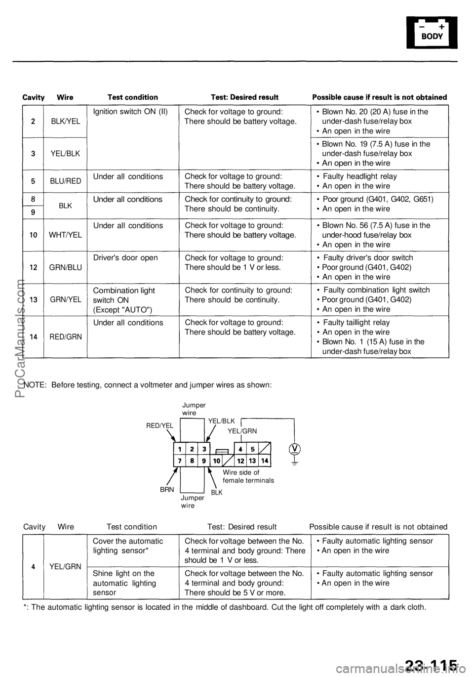
NOTE : Befor e testing , connec t a voltmete r an d jumpe r wire s a s shown :
JumperwireYEL/BL K
YEL/GR N
Wire sid e o f
femal e terminal s
BLKJumpe r
wir eBRN
RED/YE L
Cavity Wir e Tes t conditio n Test : Desire d resul t Possibl e caus e if resul t i s no t obtaine d
YEL/GR N
Cover th e automati c
lightin g sensor *
Shin e ligh t o n th e
automati c lightin g
sensor
Check fo r voltag e betwee n th e No .
4 termina l an d bod y ground : Ther e
shoul d b e 1 V or less .
Chec k fo r voltag e betwee n th e No .
4 termina l an d bod y ground :
Ther e shoul d b e 5 V or more . •
Fault y automati c lightin g senso r
• A n ope n in th e wir e
• Fault y automati c lightin g senso r
• A n ope n in th e wir e
* : Th e automati c lightin g senso r i s locate d i n th e middl e o f dashboard . Cu t th e ligh t of f completel y wit h a dar k cloth .
ProCarManuals.com
Page 1598 of 1954
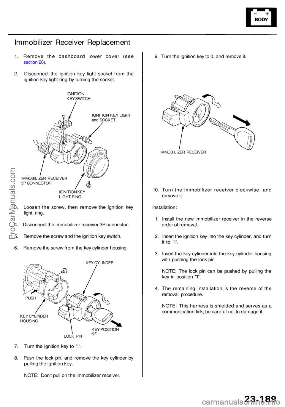
Immobilizer Receive r Replacemen t
1. Remove the dashboard lower cover (see
section 20 ).
2 . Disconnec t th e ignitio n ke y ligh t socke t fro m th e
ignitio n ke y ligh t rin g b y turnin g th e socket .
IGNITIO NKEY SWITC H
IGNITIO N KE Y LIGH T
and SOCKE T
9. Tur n th e ignitio n ke y to 0, an d remov e it .
IMMOBILIZE R RECEIVE R
10. Tur n th e immobilize r receive r clockwise , an d
remov e it .
Installation :
1. Instal l th e ne w immobilize r receive r i n th e revers e
orde r o f removal .
2 . Inser t th e ignitio n ke y int o th e ke y cylinder , an d tur n
it t o "I" .
3. Inser t th e ke y cylinde r int o th e ke y cylinde r housin g
wit h pushin g th e loc k pin .
NOTE : Th e loc k pi n ca n b e pushe d b y pullin g th e
ke y i n positio n "I" .
4 . Th e remainin g installatio n i s th e revers e o f th e
remova l procedure .
NOTE : Thi s harnes s i s shielde d an d serve s a s a
communicatio n link ; b e carefu l no t t o damag e it .
7 . Tur n th e ignitio n ke y t o "I" .
8 . Pus h th e loc k pin , an d remov e th e ke y cylinde r b y
pullin g th e ignitio n key .
NOTE : Don' t pul l o n th e immobilize r receiver .
3
. Loose n th e screw , the n remov e th e ignitio n ke y
ligh t ring .
4 . Disconnec t th e immobilize r receive r 3 P connector .
5 . Remov e th e scre w an d th e ignitio n ke y switch .
6 . Remov e th e scre w fro m th e ke y cylinde r housing .
IMMOBILIZE R RECEIVE R3P CONNECTO R
IGNITION KEYLIGH T RIN G
KEY CYLINDE RHOUSING
PUS
H
LOC K PI N
KEY POSITIO N
KEY CYLINDE R
ProCarManuals.com
Page 1657 of 1954
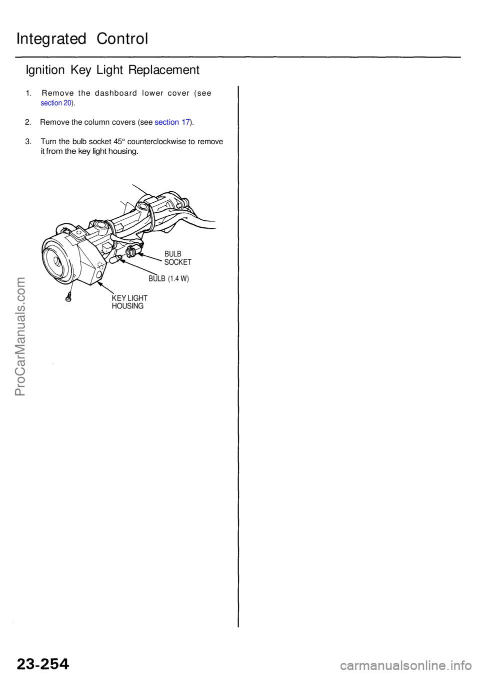
Integrated Contro l
Ignition Ke y Ligh t Replacemen t
1. Remove the dashboard lower cover (see
section 20 ).
2 . Remov e th e colum n cover s (se e sectio n 17 ).
3 . Tur n th e bul b socke t 45 ° counterclockwis e t o remov e
it fro m th e ke y ligh t housing .
BULB (1. 4 W )
KE Y LIGH THOUSIN G
BULBSOCKE T
ProCarManuals.com
Page 1796 of 1954
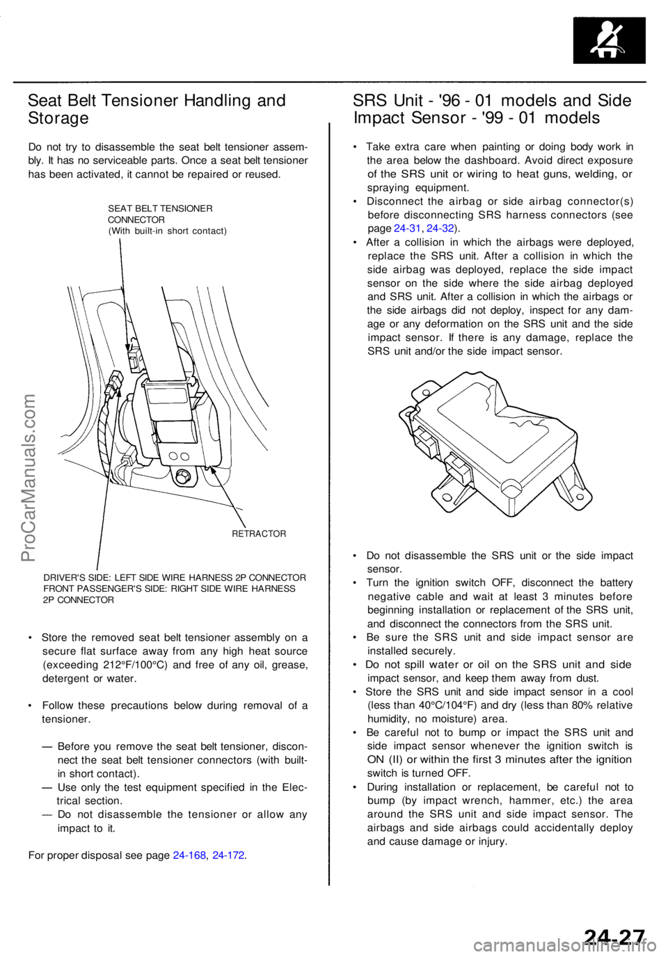
Seat Bel t Tensione r Handlin g an d
Storag e
Do no t tr y t o disassembl e th e sea t bel t tensione r assem -
bly . I t ha s n o serviceabl e parts . Onc e a sea t bel t tensione r
ha s bee n activated , i t canno t b e repaire d o r reused .
SEAT BEL T TENSIONE R
CONNECTO R
(Wit h built-i n shor t contact )
RETRACTO R
DRIVER'S SIDE : LEF T SID E WIR E HARNES S 2 P CONNECTO R
FRON T PASSENGER' S SIDE : RIGH T SID E WIR E HARNES S
2 P CONNECTO R
• Stor e th e remove d sea t bel t tensione r assembl y o n a
secur e fla t surfac e awa y fro m an y hig h hea t sourc e
(exceedin g 212°F/100°C ) an d fre e o f an y oil , grease ,
detergen t o r water .
• Follo w thes e precaution s belo w during remova l o f a
tensioner .
Befor e yo u remov e th e sea t bel t tensioner , discon -
nec t th e sea t bel t tensione r connector s (wit h built -
i n shor t contact) .
Us e onl y th e tes t equipmen t specifie d i n th e Elec -
trica l section .
D o no t disassembl e th e tensione r o r allo w an y
impac t t o it .
Fo r prope r disposa l se e pag e 24-168 , 24-172 .
SRS Uni t - '9 6 - 0 1 model s an d Sid e
Impac t Senso r - '9 9 - 0 1 model s
• Tak e extr a car e whe n paintin g o r doin g bod y wor k i n
th e are a belo w th e dashboard . Avoi d direc t exposur e
of th e SR S uni t o r wirin g t o hea t guns , welding , o r
sprayin g equipment .
• Disconnec t th e airba g o r sid e airba g connector(s )
befor e disconnectin g SR S harnes s connector s (se e
pag e 24-31 , 24-32 ).
• Afte r a collisio n i n whic h th e airbag s wer e deployed ,
replac e th e SR S unit . Afte r a collisio n i n whic h th e
sid e airba g wa s deployed , replac e th e sid e impac t
senso r o n th e sid e wher e th e sid e airba g deploye d
an d SR S unit . Afte r a collisio n i n whic h th e airbag s o r
th e sid e airbag s di d no t deploy , inspec t fo r an y dam -
ag e o r an y deformatio n o n th e SR S uni t an d th e sid e
impac t sensor . I f ther e i s an y damage , replac e th e
SR S uni t and/o r th e sid e impac t sensor .
• D o no t disassembl e th e SR S uni t o r th e sid e impac t
sensor .
• Tur n th e ignitio n switc h OFF , disconnec t th e batter y
negativ e cabl e an d wai t a t leas t 3 minute s befor e
beginnin g installatio n o r replacemen t o f th e SR S unit ,
an d disconnec t th e connector s fro m th e SR S unit .
• B e sur e th e SR S uni t an d sid e impac t senso r ar e
installe d securely .
• D o no t spil l wate r o r oi l o n th e SR S uni t an d sid e
impac t sensor , an d kee p the m awa y fro m dust .
• Stor e th e SR S uni t an d sid e impac t senso r i n a coo l
(les s tha n 40°C/104°F ) an d dr y (les s tha n 80 % relativ e
humidity , n o moisture ) area .
• B e carefu l no t t o bum p o r impac t th e SR S uni t an d
sid e impac t senso r wheneve r th e ignitio n switc h i s
ON (II ) o r withi n th e firs t 3 minute s afte r th e ignitio n
switch i s turne d OFF .
• Durin g installatio n o r replacement , b e carefu l no t t o
bum p (b y impac t wrench , hammer , etc. ) th e are a
aroun d th e SR S uni t an d sid e impac t sensor . Th e
airbag s an d sid e airbag s coul d accidentall y deplo y
an d caus e damag e o r injury .
ProCarManuals.com