Page 1511 of 1954
IGNITION CONTRO LMODULE (ICM )
UNDER-HOO D RELA YBOX B
DRIVER' S POWE R WINDO W MOTO R RELA Y B('98-0 1 models )• HOR N RELA Y('96-97 models )• POWE R WINDO W MASTE R SWITC H
RELA Y ('98-0 1 models )
CIGARETT E LIGHTE R RELA Y
• FRON T SEA T HEATE R RELA Y
('96-97 models )• DRIVER' S POWE R WINDO W MOTO R RELA Y A
('9 8-0 1 models )
SPAR K PLU G VOLTAG E
DETECTIO N MODUL E
DIMME R RELA Y •
AB S PUM P MOTO R RELA Y
('96-99 models )• VS A FAIL-SAF E RELA Y
('0 0-0 1 models )
• HEADLIGH T RELA Y
('96-98 models )• HEADLIGH T
LO W BEA M RELA Y
('99-01 models )
TAILLIGH T RELA Y
('9 6 - 9 8 models )
• HEADLIGH T HIG H BEA M RELA Y
('9 9-0 1 models )
UNDER-HOO
D
FUSE/RELAYBOX
ProCarManuals.com
Page 1516 of 1954
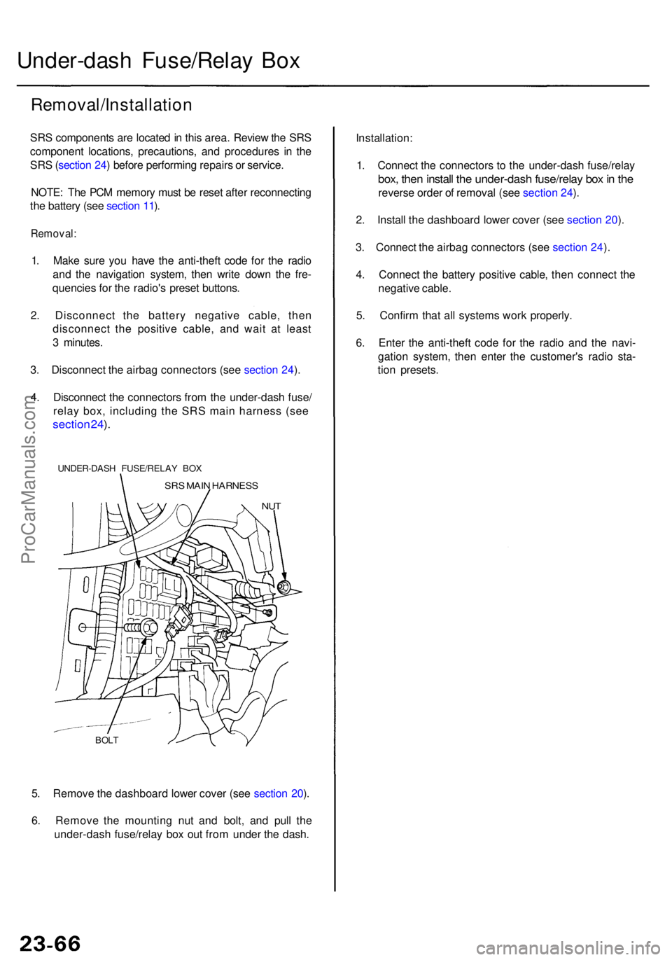
5. Remov e th e dashboar d lowe r cove r (se e sectio n 20 ).
6 . Remov e th e mountin g nu t an d bolt , an d pul l th e
under-das h fuse/rela y bo x ou t fro m unde r th e dash .
BOLT
Under-das h Fuse/Rela y Bo x
Removal/Installatio n
SRS component s ar e locate d in thi s area . Revie w th e SR S
componen t locations , precautions , an d procedure s i n th e
SR S (sectio n 24 ) befor e performin g repair s o r service .
NOTE : Th e PC M memor y mus t b e rese t afte r reconnectin g
th e batter y (se e sectio n 11 ).
Removal :
1. Mak e sur e yo u hav e th e anti-thef t cod e fo r th e radi o
an d th e navigatio n system , the n writ e dow n th e fre -
quencie s fo r th e radio' s prese t buttons .
2 . Disconnec t th e batter y negativ e cable , the n
disconnec t th e positiv e cable , an d wai t a t leas t
3 minutes .
3 . Disconnec t th e airba g connector s (se e sectio n 24 ).
4 . Disconnec t th e connector s fro m th e under-das h fuse /
relay box, including the SRS main harness (see
sectio n 24 ).
UNDER-DAS H FUSE/RELA Y BO X
SRS MAI N HARNES S
NUT
Installation :
1 . Connec t th e connector s t o th e under-das h fuse/rela y
box, the n instal l th e under-das h fuse/rela y bo x in th e
revers e orde r o f remova l (se e sectio n 24 ).
2 . Instal l th e dashboar d lowe r cove r (se e sectio n 20 ).
3 . Connec t th e airba g connector s (se e sectio n 24 ).
4 . Connec t th e batter y positiv e cable , the n connec t th e
negativ e cable .
5 . Confir m tha t al l system s wor k properly .
6 . Ente r th e anti-thef t cod e fo r th e radi o an d th e navi -
gatio n system , the n ente r th e customer' s radi o sta -
tio n presets .
ProCarManuals.com
Page 1520 of 1954
Ignition Switc h
Test
SRS component s ar e locate d i n thi s area . Revie w th e
SR S componen t locations , precautions , an d procedure s
i n th e SR S ( sectio n 24 ) befor e performin g repair s o r
service .
NOTE: Th e PC M memor y mus t b e rese t afte r reconnectin g
th e batter y (se e sectio n 11 ).
1 . Mak e sur e yo u hav e th e anti-thef t cod e fo r th e radi o
an d th e navigatio n system , the n writ e dow n th e fre -
quencie s fo r th e radio' s prese t buttons .
2 . Disconnec t th e batter y negativ e cable .
3 . Remov e th e dashboar d lowe r cove r (se e sectio n 20 ).
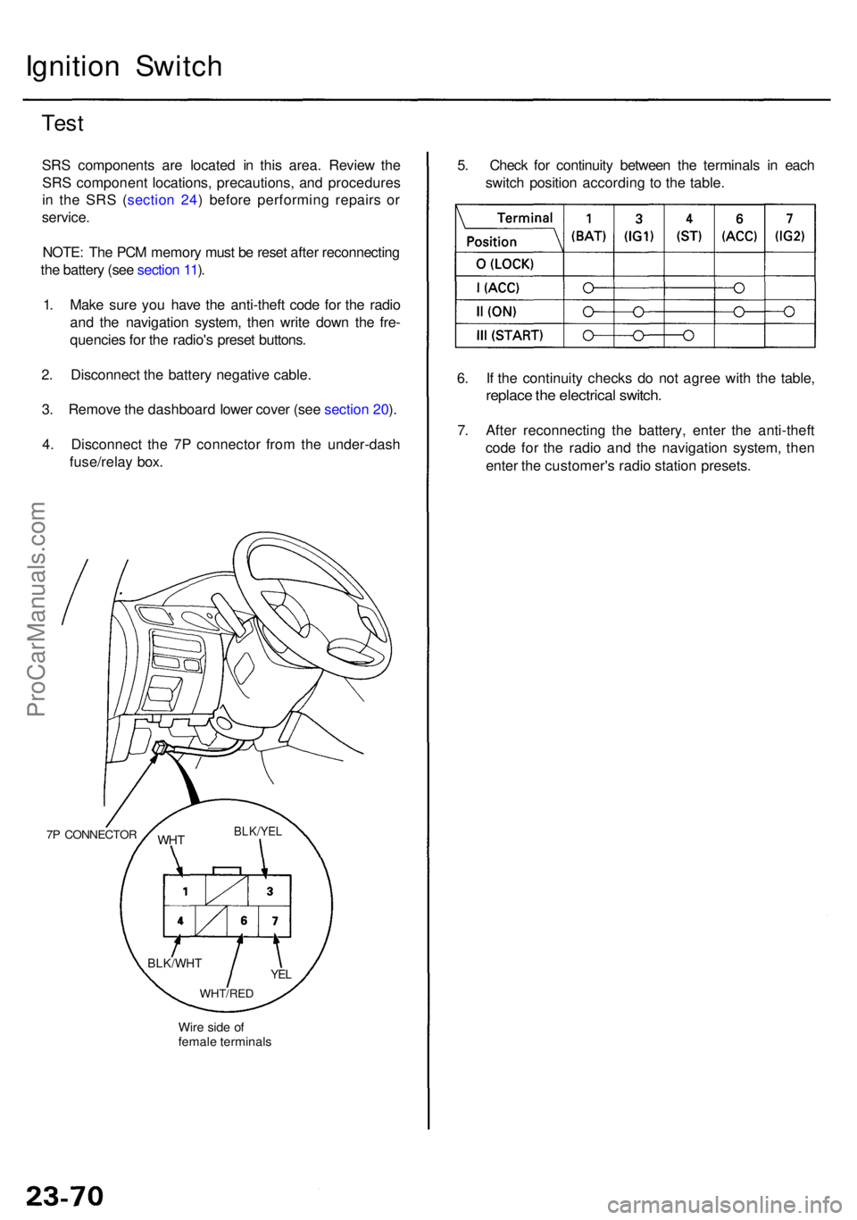
4 . Disconnec t th e 7 P connecto r fro m th e under-das h
fuse/rela y box .
7P CONNECTO R
Wire sid e o f
femal e terminal s
WHTBLK/YE L
YEL
WHT/RE D
BLK/WH T
5. Chec k fo r continuit y betwee n th e terminal s i n eac h
switc h positio n accordin g t o th e table .
6 . I f th e continuit y check s d o no t agre e wit h th e table ,
replac e th e electrica l switch .
7. Afte r reconnectin g th e battery , ente r th e anti-thef t
cod e fo r th e radi o an d th e navigatio n system , the n
ente r th e customer' s radi o statio n presets .
ProCarManuals.com
Page 1521 of 1954
8. Afte r reconnectin g th e battery , ente r th e anti-thef t
cod e fo r th e radi o an d th e navigatio n system , the n
ente r th e customer' s radi o statio n presets .
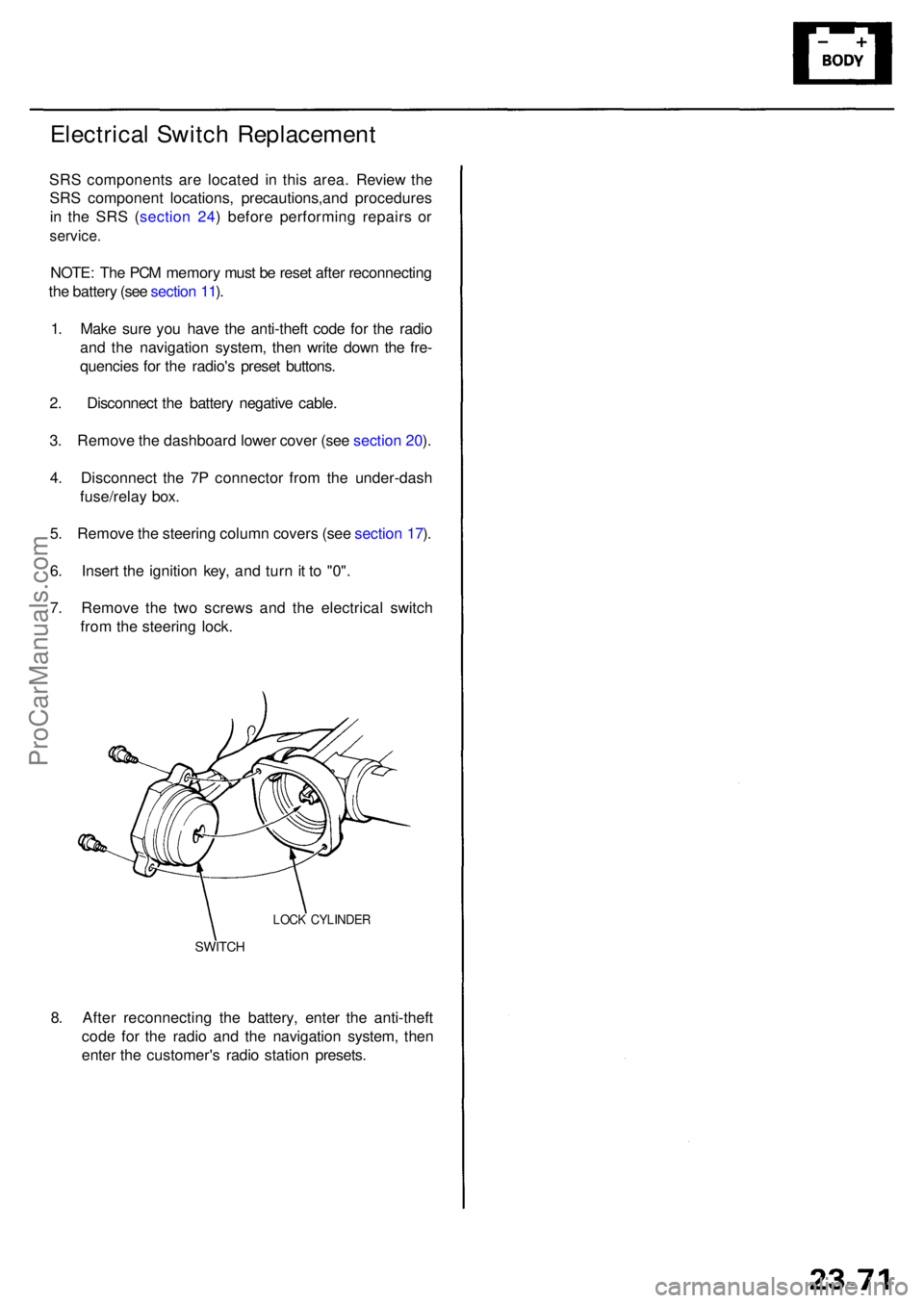
SWITCH
LOCK CYLINDE R
Electrical Switc h Replacemen t
SRS component s ar e locate d i n thi s area . Review the
SR S componen t locations , precautions,an d procedure s
i n th e SR S ( sectio n 24 ) befor e performin g repair s o r
service .
NOTE: Th e PC M memor y mus t b e rese t afte r reconnectin g
th e batter y (se e sectio n 11 ).
1 . Mak e sur e yo u hav e th e anti-thef t cod e fo r th e radi o
an d th e navigatio n system , the n writ e dow n th e fre -
quencie s fo r th e radio' s prese t buttons .
2 . Disconnec t th e batter y negativ e cable .
3 . Remov e th e dashboar d lowe r cove r (se e sectio n 20 ).
4 . Disconnec t th e 7 P connecto r fro m th e under-das h
fuse/rela y box .
5 . Remov e th e steerin g colum n cover s (se e sectio n 17 ).
6 . Inser t th e ignitio n key , an d tur n it t o "0" .
7 . Remov e th e tw o screw s an d th e electrica l switc h
fro m th e steerin g lock .
ProCarManuals.com
Page 1529 of 1954
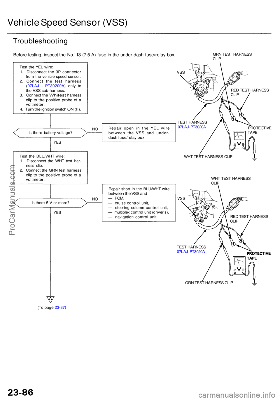
(To page 23-87) GR
N TES T HARNES S CLI P
TES
T HARNES S
07LA J-PT3020 A
Vehicle Spee d Senso r (VSS )
Troubleshootin g
Before testing , inspec t th e No . 1 3 (7. 5 A ) fus e in th e under-das h fuse/rela y box .
Test th e YE L wire :
1 . Disconnec t th e 3 P connecto r
fro m th e vehicl e spee d sensor .
2 . Connec t th e tes t harnes s
( 07LA J - PT30200A ) onl y t o
th e VS S sub-harness .
3. Connec t the Whites t harnes sclip t o th e positiv e prob e o f avoltmeter .4. Tur n th e ignitio n switc h O N (II) .
Is ther e batter y voltage ? Repai
r ope n i n th e YE L wir e
betwee n th e VS S an d under -
das h fuse/rela y box .NO
YE S
Tes t th e BLU/WH T wire :
1 . Disconnec t th e WH T tes t har -
nes s clip .
2 . Connec t th e GR N tes t harnes s
clip t o th e positiv e prob e o f avoltmeter .
Is ther e 5 V or more ?NO
Repai r shor t i n th e BLU/WH T wir ebetwee n th e VS S an d— PCM ,— cruis e contro l unit ,
— steerin g colum n contro l unit ,
— multiple x contro l uni t (driver's) ,
— navigatio n contro l unit .
YES
GR N TES T HARNES SCLIP
VSS
TES T HARNES S
07LA J-PT3020 A RE
D TES T HARNES S
CLIP
PROTECTIV ETAPE
WHT TES T HARNES S CLI P
WH T TES T HARNES S
CLIP
VSS
RE D TES T HARNES SCLIP
ProCarManuals.com
Page 1546 of 1954
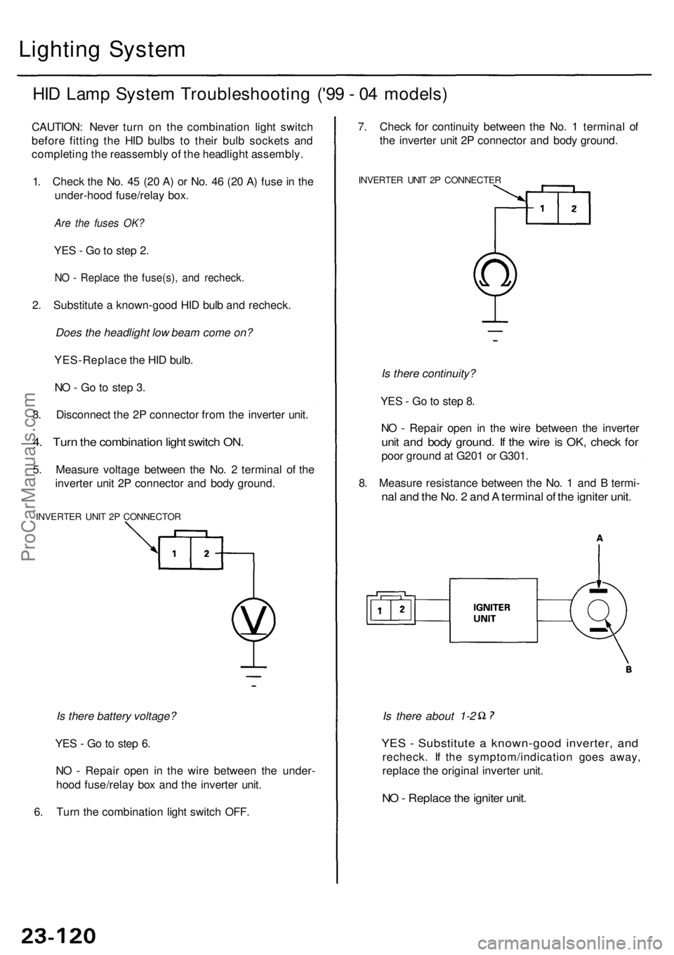
Lighting Syste m
HID Lam p Syste m Troubleshootin g ('9 9 - 0 4 models )
CAUTION : Neve r tur n o n th e combinatio n ligh t switc h
befor e fittin g th e HI D bulb s t o thei r bul b socket s an d
completin g th e reassembl y o f th e headligh t assembly .
1 . Chec k th e No . 4 5 (2 0 A ) o r No . 4 6 (2 0 A ) fus e in th e
under-hoo d fuse/rela y box .
Are the fuses OK?
YES - G o to ste p 2 .
NO - Replac e th e fuse(s) , an d recheck .
2. Substitut e a known-goo d HI D bul b an d recheck .
Does the headlight low beam come on?
YES-Replac e th e HI D bulb .
N O - G o t o ste p 3 .
3 . Disconnec t th e 2 P connecto r fro m th e inverte r unit .
4. Tur n th e combinatio n ligh t switc h ON .
5. Measur e voltag e betwee n th e No . 2 termina l o f th e
inverte r uni t 2 P connecto r an d bod y ground .
INVERTE R UNI T 2 P CONNECTO R
Is there battery voltage?
YE S - G o to ste p 6 .
N O - Repai r ope n i n th e wir e betwee n th e under -
hoo d fuse/rela y bo x an d th e inverte r unit .
6 . Tur n th e combinatio n ligh t switc h OFF .
YES - Substitut e a known-goo d inverter , an d
recheck . I f th e symptom/indicatio n goe s away ,
replac e th e origina l inverte r unit .
NO - Replac e th e ignite r unit .
Is there about 1-2
7
. Chec k fo r continuit y betwee n th e No . 1 termina l o f
th e inverte r uni t 2 P connecto r an d bod y ground .
INVERTE R UNI T 2 P CONNECTE R
Is there continuity?
YE S - G o to ste p 8 .
N O - Repai r ope n i n th e wir e betwee n th e inverte r
unit an d bod y ground . I f th e wir e is OK , chec k fo r
poo r groun d a t G20 1 o r G301 .
8 . Measur e resistanc e betwee n th e No . 1 an d B termi -
nal an d th e No . 2 an d A termina l o f th e ignite r unit .
ProCarManuals.com
Page 1557 of 1954
Turn Signal/Hazar d Flashe r Syste m
Turn Signal/Hazar d Rela y Inpu t Tes t
1. Remov e th e driver' s sid e kic k panel , the n remov e
th e tur n signal/hazar d rela y fro m th e under-das h
fuse/rela y box .
2 . Inspec t th e rela y an d socke t terminal s t o b e sur e
they ar e al l makin g goo d contact .
• I f th e terminal s ar e bent , loos e o r corroded , repai r
the m as necessary , an d rechec k th e system .
• I f th e terminal s loo k OK , mak e th e followin g
inpu t test s a t th e socket .
If an y tes t indicate s a problem , fin d an d
correc t th e cause , the n rechec k th e system .
I f al l th e inpu t test s prov e OK , th e tur n signal /
hazar d rela y mus t b e faulty ; replac e it .
UNDER-DAS HFUSE/RELAY BO X
TUR N SIGNAL /HAZARD RELA Y
Cavity Tes t conditio n Test : Desire d resul t Possibl e caus e if resul t i s no t obtaine d
*1 : '9 6 -9 8 model s
*2: '99-0 1 model s
ProCarManuals.com
Page 1579 of 1954
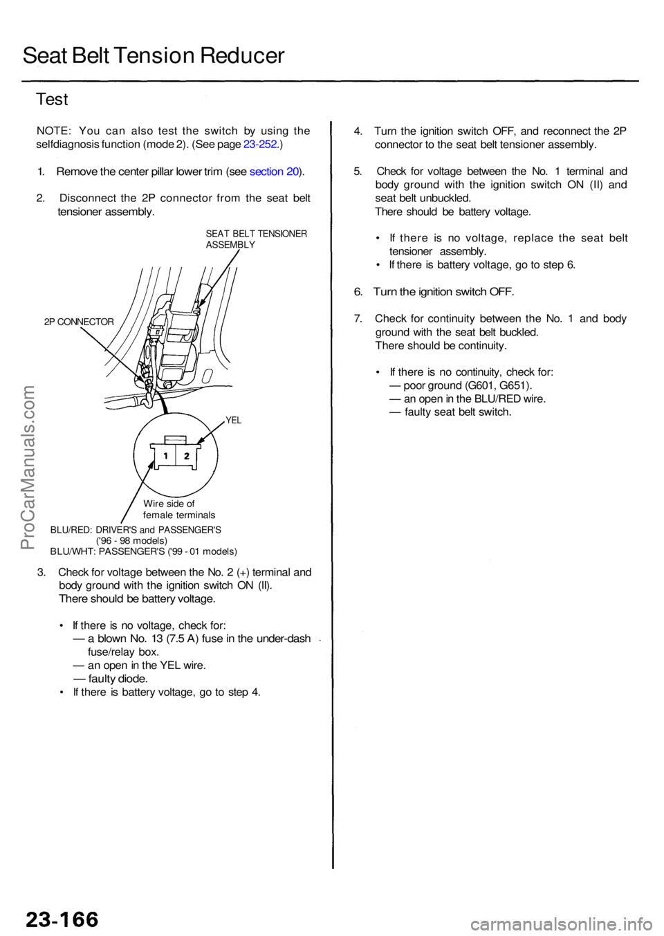
Seat Bel t Tensio n Reduce r
Test
NOTE : Yo u ca n als o tes t th e switc h b y usin g th e
selfdiagnosi s functio n (mod e 2) . (Se e pag e 23-252 .)
1 . Remov e th e cente r pilla r lowe r tri m (se e sectio n 20 ).
2 . Disconnec t th e 2 P connecto r fro m th e sea t bel t
tensione r assembly .
SEAT BEL T TENSIONE RASSEMBLY
2P CONNECTO R
YEL
4. Tur n th e ignitio n switc h OFF , an d reconnec t th e 2 P
connecto r t o th e sea t bel t tensione r assembly .
5 . Chec k fo r voltag e betwee n th e No . 1 termina l an d
bod y groun d wit h th e ignitio n switc h O N (II ) an d
sea t bel t unbuckled .
Ther e shoul d b e batter y voltage .
• I f ther e i s n o voltage , replac e th e sea t bel t
tensione r assembly .
• I f ther e is batter y voltage , g o to ste p 6 .
6. Tur n th e ignitio n switc h OFF .
7. Chec k fo r continuit y betwee n th e No . 1 an d bod y
groun d wit h th e sea t bel t buckled .
Ther e shoul d b e continuity .
• I f ther e is n o continuity , chec k for :
— poo r groun d (G601 , G651) .
— an ope n in th e BLU/RE D wire .
— fault y sea t bel t switch .
3 . Chec k fo r voltag e betwee n th e No . 2 (+ ) termina l an d
bod y groun d wit h th e ignitio n switc h O N (II) .
Ther e shoul d b e batter y voltage .
• I f ther e is n o voltage , chec k for :
— a blow n No . 1 3 (7. 5 A ) fus e in th e under-das h
fuse/relay box .
— an ope n in th e YE L wire .
— fault y diode .
• I f ther e i s batter y voltage , g o t o ste p 4 .
BLU/RED : DRIVER' S an d PASSENGER' S('96 - 9 8 models )
BLU/WHT : PASSENGER' S ('9 9 - 0 1 models )
Wir
e sid e o f
femal e terminal s
ProCarManuals.com