1996 ACURA RL KA9 fuse box
[x] Cancel search: fuse boxPage 1127 of 1954
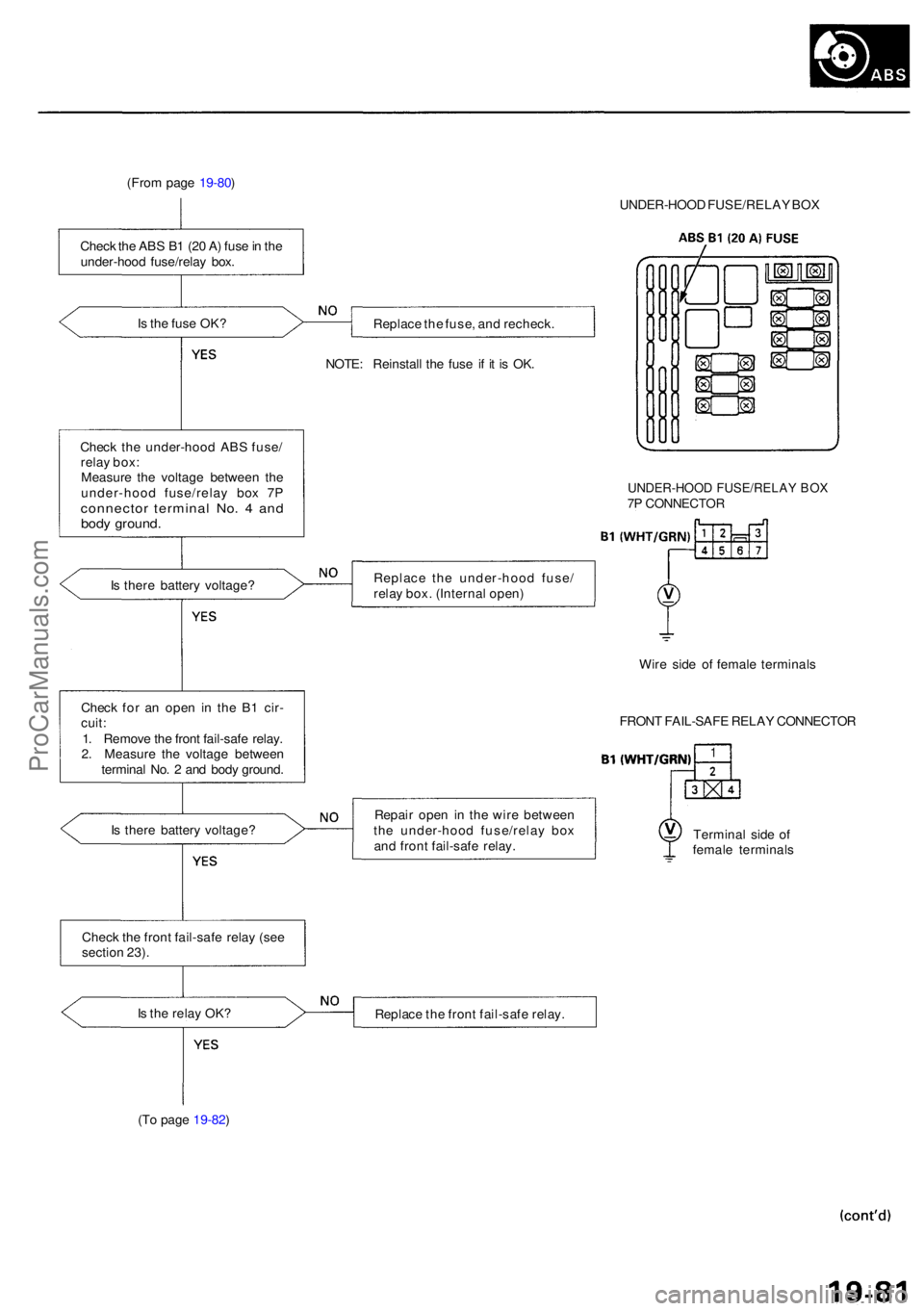
(From pag e 19-80 )
I s th e fus e OK ?
Chec k th e under-hoo d AB S fuse /
rela y box :
Measur e th e voltag e betwee n th e
under-hoo d fuse/rela y bo x 7 P
connecto r termina l No . 4 an dbod y ground .
Is ther e batter y voltage ?
Chec k fo r a n ope n i n th e B 1 cir -
cuit :
1 . Remov e th e fron t fail-saf e relay .
2 . Measur e th e voltag e betwee n
termina l No . 2 an d bod y ground .
I s ther e batter y voltage ?
I s th e rela y OK ?
(T o pag e 19-82 ) UNDER-HOO
D FUSE/RELA Y BO X
Replac e th e fuse , an d recheck .
NOTE : Reinstal l th e fus e i f i t i s OK .
UNDER-HOO D FUSE/RELA Y BO X7P CONNECTO R
Repair ope n i n th e wir e betwee n
th e under-hoo d fuse/rela y bo x
an d fron t fail-saf e relay .
1
Termina l sid e o f
femal e terminal s
Replac e th e fron t fail-saf e relay .
Chec
k th e fron t fail-saf e rela y (se e
sectio n 23) . FRON
T FAIL-SAF E RELA Y CONNECTO R
Replac
e th e under-hoo d fuse /
rela y box . (Interna l open )
Wire sid e o f femal e terminal s
Chec
k th e AB S B 1 (2 0 A ) fus e in th e
under-hoo d fuse/rela y box .
ProCarManuals.com
Page 1151 of 1954
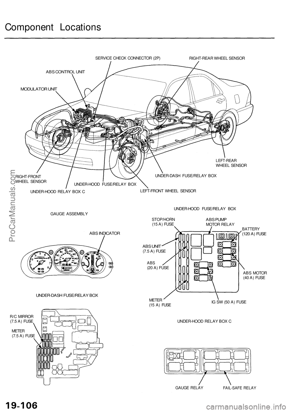
Component Locations
SERVICE CHECK CONNECTOR (2P)
RIGHT-REAR WHEEL SENSOR
ABS CONTROL UNIT
MODULATOR UNIT
LEFT-REAR
WHEEL SENSOR
RIGHT-FRONT
WHEEL SENSOR
UNDER-HOOD RELAY BOX C
UNDER-DASH FUSE/RELAY BOX
LEFT-FRONT WHEEL SENSOR
GAUGE ASSEMBLY
UNDER-HOOD FUSE/RELAY BOX
ABS INDICATOR
UNDER-DASH FUSE/RELAY BOX
R/C MIRROR
(7.5 A) FUSE
METER
(7.5 A) FUSE
STOP/HORN
(15 A) FUSE
ABS
UNIT
(7.5 A) FUSE
ABS
(20 A) FUSE
ABS PUMP
MOTOR RELAY
METER
(15 A) FUSE
BATTERY
(120 A) FUSE
ABS MOTOR
(40 A) FUSE
IG SW (50 A) FUSE
UNDER-HOOD RELAY BOX C
GAUGE RELAY
FAIL-SAFE RELAY
UNDER-HOOD FUSE/RELAY BOXProCarManuals.com
Page 1165 of 1954
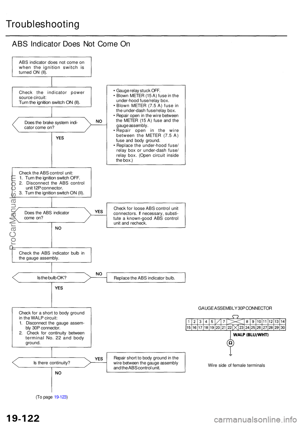
Troubleshooting
ABS Indicato r Doe s No t Com e O n
AB S indicato r doe s no t com e o nwhe n th e ignitio n switc h i sturne d O N (II) .
Chec k th e indicato r powe r
sourc e circuit :
Turn th e ignitio n switc h O N (II) .
Doe s th e brak e syste m indi -cato r com e on ?
Chec k th e AB S contro l unit :
1. Tur n th e ignitio n switc h OFF .2. Disconnec t th e AB S contro lunit 12 P connector .3. Tur n th e ignitio n switc h O N (II) .
Doe s th e AB S indicato r
com e on ?
Is th e bul b OK ?
Chec k fo r a shor t t o bod y groun d
i n th e WAL P circuit :
1 . Disconnec t th e gaug e assem -
bl y 30 P connector .
2 . Chec k fo r continuit y betwee n
termina l No . 2 2 an d bod yground .
I s ther e continuity ?
(T o pag e 19-123 ) Gaug
e rela y stuc k OFF .
Blow n METE R (1 5 A ) fus e in th e
under-hoo d fuse/rela y box .
Blow n METE R (7. 5 A ) fus e i n
th e under-das h fuse/rela y box .
Repai r ope n in th e wir e betwee n
th e METE R (1 5 A ) fus e an d th e
gaug e assembly .
Repai r ope n i n th e wir e
betwee n th e METE R (7. 5 A )
fus e an d bod y ground .
Replac e th e under-hoo d fuse /
rela y bo x o r under-das h fuse /
rela y box . (Ope n circui t insid e
the box. )
Chec k fo r loos e AB S contro l uni t
connectors . I f necessary , substi -
tut e a known-goo d AB S contro l
uni t an d recheck .
Replac e th e AB S indicato r bulb .
GAUGE ASSEMBL Y 30 P CONNECTO R
Repai r shor t t o bod y groun d in th e
wir e betwee n th e gaug e assembl y
and th e AB S contro l unit .Wire sid e o f femal e terminal s
Chec
k th e AB S indicato r bul b i n
th e gaug e assembly .
ProCarManuals.com
Page 1167 of 1954
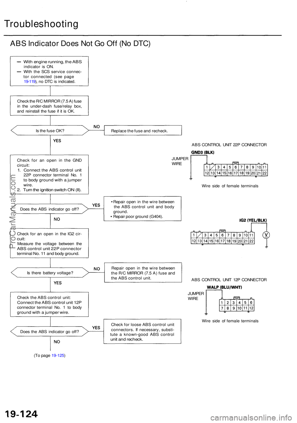
Troubleshooting
ABS Indicato r Doe s No t G o Of f (N o DTC )
Is th e fus e OK ?
Chec k fo r a n ope n i n th e GN D
circuit :
1. Connec t th e AB S contro l uni t22P connecto r termina l No . 1to bod y groun d wit h a jumpe rwire.2. Tur n th e ignitio n switc h O N (II) .
Doe s th e AB S indicato r g o off ?
Chec k fo r a n ope n in th e IG 2 cir -
cuit :Measur e th e voltag e betwee n th eAB S contro l uni t 22 P connecto rterminal No . 1 1 an d bod y ground .
Is ther e batter y voltage ?
Chec k th e AB S contro l unit :
Connec t th e AB S contro l uni t 12 Pconnecto r termina l No . 1 to bod ygroun d wit h a jumpe r wire .
Does th e AB S indicato r g o off ?
(T o pag e 19-125 ) Replac
e th e fus e an d recheck .
ABS CONTRO L UNI T 22 P CONNECTO R
Wir e sid e o f femal e terminal s
Repai r ope n in th e wir e betwee n
th e AB S contro l uni t an d bod y
ground .
Repai r poo r groun d (G404) .
Repai r ope n in th e wir e betwee n
th e R/ C MIRRO R (7. 5 A ) fus e an d
th e AB S contro l unit .
Chec k fo r loos e AB S contro l uni t
connectors . I f necessary , substi -
tut e a known-goo d AB S contro l
unit an d recheck .
Wire sid e o f femal e terminal s
AB
S CONTRO L UNI T 12 P CONNECTO R
JUMPE R
WIRE
JUMPE R
WIR E
With engin e running , th e AB Sindicato r i s ON .
Wit h th e SC S servic e connec -
to r connecte d (se e pag e
19-119 ), n o DT C is indicated .
Chec k th e R/ C MIRRO R (7. 5 A ) fus e
i n th e under-das h fuse/rela y box ,
an d reinstal l th e fus e if i t i s OK .
ProCarManuals.com
Page 1177 of 1954
Troubleshooting
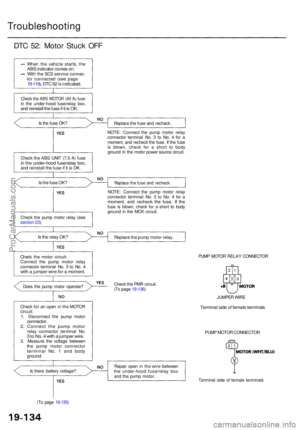
DTC 52 : Moto r Stuc k OF F
Whe n th e vehicl e starts , th eAB S indicato r conie s on .Wit h th e SC S servic e connec -
to r connecte d (se e pag e
19-119 ), DT C 52 is indicated .
Check th e AB S MOTO R (4 0 A ) fus ein th e under-hoo d fuse/rela y box ,and reinstal l th e fus e if i t i s OK .
Is th e fus e OK ?
Chec k th e AB S UNI T (7. 5 A ) fus e
in th e under-hoo d fuse/rela y box ,and reinstal l th e fus e if i t i s OK .
I s th e fus e OK ?
Chec k th e pum p moto r rela y (se e
sectio n 23 ).
I s th e rela y OK ?
Chec k th e moto r circuit :
Connec t th e pum p moto r rela y
connecto r termina l No . 3 to No . 4
wit h a jumpe r wir e fo r a moment .
Does th e pum p moto r operate ?
Chec k fo r a n ope n in th e MOTO R
circuit :
1 . Disconnec t th e pum p moto r
connector .2. Connec t th e pum p moto rrelay connecto r termina l No .3 to No . 4 wit h a jumpe r wire .3. Measur e th e voltag e betwee n
th e pum p moto r connecto r
terminal No . 1 an d bod yground .
Is ther e batter y voltage ?
(T o pag e 19-135 ) Replac
e th e fus e an d recheck .
NOTE : Connec t th e pum p moto r rela y
connecto r termina l No . 3 to No . 4 fo r a
moment , an d rechec k th e fuse . I f th e fus e
i s blown , chec k fo r a shor t t o bod y
groun d i n th e moto r powe r sourc e circuit .
Replac e th e fus e an d recheck .
NOTE: Connec t th e pum p moto r rela y
connecto r termina l No . 3 to No . 4 fo r a
moment , an d rechec k th e fuse . I f th efus e i s blown , chec k fo r a shor t t o bod y
groun d i n th e MC K circuit .
Replac e th e pum p moto r relay .
PUMP MOTO R RELA Y CONNECTO R
Chec k th e PM R circuit .
(T o pag e 19-136 )
Repai r ope n in th e wir e betwee n
th e under-hoo d fuse/rela y bo x
an d th e pum p motor .
Terminal sid e o f femal e terminal s
PUM
P MOTO R CONNECTO R
JUMPE
R WIR E
Termina l sid e o f femal e terminal s
ProCarManuals.com
Page 1180 of 1954
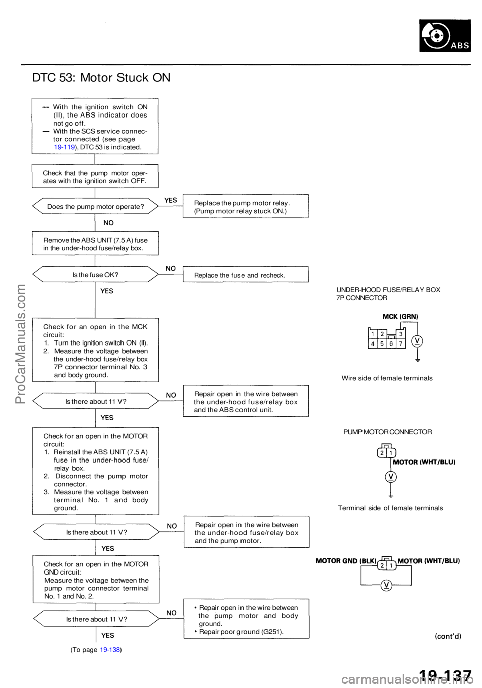
DTC 53 : Moto r Stuc k O N
Wit h th e ignitio n switc h O N
(II) , th e AB S indicato r doe s
not g o off .Wit h th e SC S servic e connec -
to r connecte d (se e pag e
19-119 ), DT C 53 is indicated .
Chec k tha t th e pum p moto r oper -
ate s wit h th e ignitio n switc h OFF .
Doe s th e pum p moto r operate ?
Remov e th e AB S UNI T (7. 5 A ) fus e
i n th e under-hoo d fuse/rela y box .
I s th e fus e OK ?
Chec k fo r a n ope n i n th e MC K
circuit :1. Tur n th e ignitio n switc h O N (II) .
2 . Measur e th e voltag e betwee n
th e under-hoo d fuse/rela y bo x
7P connecto r termina l No . 3an d bod y ground .
I s ther e abou t 1 1 V ?
Chec k fo r a n ope n in th e MOTO R
circuit:1. Reinstal l th e AB S UNI T (7. 5 A )
fus e i n th e under-hoo d fuse /
rela y box .
2 . Disconnec t th e pum p moto r
connector .3. Measur e th e voltag e betwee n
termina l No . 1 an d bod y
ground .
I s ther e abou t 1 1 V ?
Chec k fo r a n ope n in th e MOTO R
GN D circuit :
Measur e th e voltag e betwee n th e
pum p moto r connecto r termina l
No. 1 an d No . 2 .
Is ther e abou t 1 1 V ?
(To pag e 19-138 )
Replac e th e pum p moto r relay .
(Pum p moto r rela y stuc k ON. )
Replac e th e fus e an d recheck .
UNDER-HOO D FUSE/RELA Y BO X7P CONNECTO R
Wire sid e o f femal e terminal s
Repai r ope n in th e wir e betwee n
th e under-hoo d fuse/rela y bo x
an d th e AB S contro l unit .
PUMP MOTO R CONNECTO R
Termina l sid e o f femal e terminal s
Repai r ope n in th e wir e betwee n
th e under-hoo d fuse/rela y bo x
an d th e pum p motor .
Repai r ope n in th e wir e betwee n
th e pum p moto r an d bod y
ground .Repair poo r groun d (G251) .
ProCarManuals.com
Page 1182 of 1954
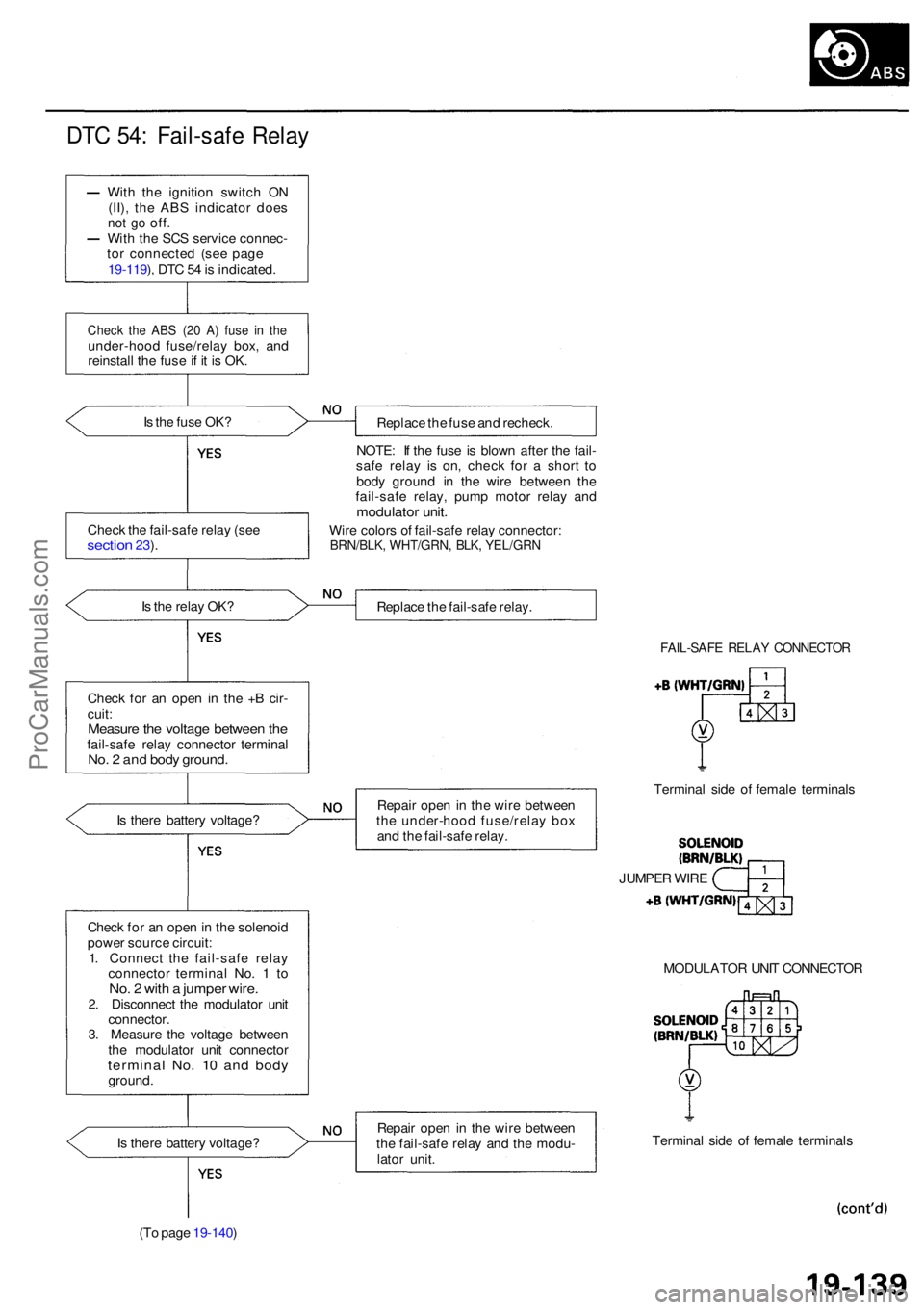
DTC 54 : Fail-saf e Rela y
With th e ignitio n switc h O N
(II) , th e AB S indicato r doe s
not g o off .With th e SC S servic e connec -
to r connecte d (se e pag e
19-119 ), DT C 5 4 is indicated .
Check th e AB S (2 0 A ) fus e i n th eunder-hoo d fuse/rela y box , an d
reinstal l th e fus e if i t i s OK .
I s th e fus e OK ?
Replace th e fus e an d recheck .
NOTE : I f th e fus e i s blow n afte r th e fail -
saf e rela y i s on , chec k fo r a shor t t o
bod y groun d i n th e wir e betwee n th e
fail-saf e relay , pum p moto r rela y an d
modulato r unit .
Wire color s o f fail-saf e rela y connector :BRN/BLK, WHT/GRN , BLK , YEL/GR N
Is th e rela y OK ?
Replace th e fail-saf e relay .
Chec k fo r a n ope n in th e + B cir -
cuit :
Measur e th e voltag e betwee n th efail-saf e rela y connecto r termina lNo. 2 an d bod y ground .
FAIL-SAF E RELA Y CONNECTO R
Is ther e batter y voltage ? Repai
r ope n in th e wir e betwee n
th e under-hoo d fuse/rela y bo x
an d th e fail-saf e relay . Termina
l sid e o f femal e terminal s
Chec k fo r a n ope n in th e solenoi d
powe r sourc e circuit :
1 . Connec t th e fail-saf e rela y
connecto r termina l No . 1 to
No . 2 wit h a jumpe r wire .2. Disconnec t th e modulato r uni t
connector .
3 . Measur e th e voltag e betwee n
th e modulato r uni t connecto r
terminal No . 1 0 an d bod yground . MODULATO
R UNI T CONNECTO R
I s ther e batter y voltage ?
(T o pag e 19-140 ) Repai
r ope n in th e wir e betwee n
th e fail-saf e rela y an d th e modu -
lato r unit . Termina
l sid e o f femal e terminal s
JUMPE
R WIR E
Chec
k th e fail-saf e rela y (se e
sectio n 23).
ProCarManuals.com
Page 1183 of 1954
Troubleshooting
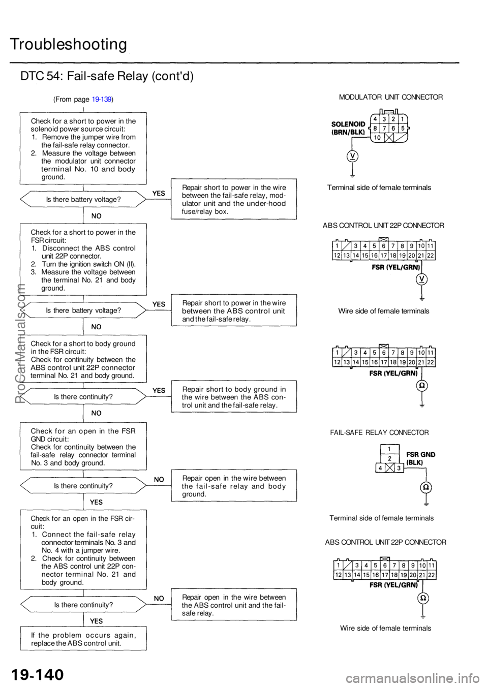
DTC 54 : Fail-saf e Rela y (cont'd )
(From pag e 19-139 )
Chec k fo r a shor t t o powe r i n th e
solenoi d powe r sourc e circuit :
1 . Remov e th e jumpe r wir e fro m
th e fail-safe relay connector .
2 . Measur e th e voltag e betwee n
th e modulato r uni t connecto r
terminal No . 1 0 an d bod yground .
I s ther e batter y voltage ?
Chec k fo r a shor t t o powe r i n th e
FS R circuit :1. Disconnec t th e AB S contro lunit 22 P connector .
2 . Tur n th e ignitio n switc h O N (II) .
3 . Measur e th e voltag e betwee n
th e termina l No . 2 1 an d bod y
ground .
I s ther e batter y voltage ?
Chec k fo r a shor t t o bod y groun d
i n th e FS R circuit :
Chec k fo r continuit y betwee n th e
AB S contro l uni t 22 P connecto rterminal No . 2 1 an d bod y ground .
I s ther e continuity ?
Chec k fo r a n ope n i n the FSR
GN D circuit :
Chec k fo r continuit y betwee n th e
fail-saf e rela y connecto r termina l
No . 3 an d bod y ground .
I s ther e continuity ?
Check fo r a n ope n in th e FS R cir -cuit :1. Connec t th e fail-saf e rela yconnecto r terminal s No . 3 an dNo. 4 wit h a jumpe r wire .
2 . Chec k fo r continuit y betwee n
th e AB S contro l uni t 22 P con -
necto r termina l No . 2 1 an d
bod y ground .
I s ther e continuity ?
I f th e proble m occur s again ,
replac e th e AB S contro l unit . Repai
r shor t t o powe r i n th e wir e
betwee n th e fail-saf e relay , mod -
ulator uni t an d th e under-hoo dfuse/relay box .
Termina l sid e o f femal e terminal s
ABS CONTRO L UNI T 22 P CONNECTO R
Repai r shor t t o powe r i n th e wir e
betwee n th e AB S contro l uni tand th e fail-saf e relay .Wire sid e o f femal e terminal s
Repair shor t t o bod y groun d in
th e wir e betwee n th e AB S con -
tro l uni t an d th e fail-saf e relay .
FAIL-SAF E RELA Y CONNECTO R
Repair ope n in th e wir e betwee n
th e fail-saf e rela y an d bod y
ground .
Termina l sid e o f femal e terminal s
AB S CONTRO L UNI T 22 P CONNECTO R
Repai r ope n i n th e wir e betwee n
th e AB S contro l uni t an d th e fail -
saf e relay .
Wire sid e o f femal e terminal s
MODULATO
R UNI T CONNECTO R
ProCarManuals.com