Page 1097 of 2543
RADIATOR REMOVAL
Installation is in the reverse order of removal.
1. REMOVE ENGINE UNDER COVER
INSTALLATION HINT: Start the engine, and check for cool-
ant and A/T fluid leaks.
2. REMOVE BATTERY AND BATTERY TRAY
3. DRAIN ENGINE COOLANT
4. 2JZ±GTE:
REMOVE NO.2 AIR TUBE
5. REMOVE NO.2 FAN SHROUD
(a) Remove the 2 clips.
(b) Disconnect the claw of the No.2 fan shroud from the hook of
the No.1 fan shroud, and remove the No.2 fan shroud.
6. REMOVE AIR CLEANER DUCT
7. 2JZ±GTE:
REMOVE NO.5 AIR HOSE
8. REMOVE LH HEADLIGHT BEAM ANGLE GAUGE
Remove the screw and beam angle gauge.
9. DISCONNECT HOSES FROM RADIATOR
Disconnect these hoses from the radiator:
(1) Reservoir inlet hose
(2) Upper radiator hose
(3) Lower radiator hose
(4) A/T:
2 oil cooler hoses
Plug the hose ends.
INSTALLATION HINT: Check the A/T fluid level.
(See item 21 in Maintenance) EG±346
± ENGINECOOLING SYSTEM
Page 1101 of 2543
 Clean the O±ring contact surface of the lower tank and oil
cooler.
(b) Install new O±ring (1) to the oil cooler (2).
(c) Install the")
RADIATOR ASSEMBLY
1. A/T:
INSTALL OIL COOLER TO LOWER TANK
(a) Clean the O±ring contact surface of the lower tank and oil
cooler.
(b) Install new O±ring (1) to the oil cooler (2).
(c) Install the oil cooler (2) to the lower tank (3).
(d) Install the plate washers (4), and nuts (5).
Torque: 8.3 NVm (85 kgfVcm, 74 in.Vlbf)
(e) Install the inlet pipes (6).
Torque: 15 NVm (150 kgfVcm, 11 ftVlbf)
HINT: Face the inlet pipes in the same direction they were be-
fore disassembly.
2. INSPECT LOCK PLATE
Inspect the lock plate for damage.
HINT:
wIf the sides of the lock plate groove are deformed,
reassembly of the tank will be impossible.
wTherefore, first correct any deformation with pliers or
similar object. Water leakage will result if the bottom of
the lock plate groove is damaged or dented. Therefore,
repair or replace if necessary.
3. INSTALL NEW O±RINGS AND TANKS
(a) After checking that there are no foreign objects in the lock
plate groove, install the new O±ring without twisting it.
HINT: When cleaning the lock plate groove, lightly rub it with
sand paper without scratching it.
(b) Install the tank without damaging the O±ring.
(c) Tap the lock plate with a soft±faced hammer so that there is
no gap between it and the tank. EG±350
± ENGINECOOLING SYSTEM
Page 1107 of 2543

Switch
ECT SWITCH INSPECTION
1. REMOVE ENGINE UNDER COVER
2. DRAIN ENGINE COOLANT
3. REMOVE ECT SWITCH
(a) Disconnect the ECT switch connector.
(b) Remove the ECT")
Engine Coolant Temperature (ECT)
Switch
ECT SWITCH INSPECTION
1. REMOVE ENGINE UNDER COVER
2. DRAIN ENGINE COOLANT
3. REMOVE ECT SWITCH
(a) Disconnect the ECT switch connector.
(b) Remove the ECT switch.
(c) Remove the O±ring from the ECT switch.
4. INSPECT ECT SWITCH
(a) Usin g an oh mme te r, ch e ck th a t th e re is no co n tin u ity
between the terminals when the coolant temperature is
above 97°C (207°F).
(b) Using an ohmmeter, check that there is continuity between
the terminals when the coolant temperature is below 88°C
(190°F).
If continuity is not as specified, replace the switch.
5. REINSTALL ECT SWITCH
(a) Install a new O±ring to the ECT switch.
(b) Apply soapy water to the O±ring.
(c) Install the ECT switch.
Torque: 7.4 NVm (75 kgfVcm, 65 in.Vlbf)
(d) Connect the ECT switch connector.
6. REFILL WITH ENGINE COOLANT
7. START ENGINE AND CHECK FOR LEAKS
8. REINSTALL ENGINE UNDER COVER
No.1 Radiator Fan Relay
(ºRADIATOR FAN RELAYº)
RADIATOR FAN RELAY INSPECTION
1. w/ Auto Spoiler:
REMOVE LH HEADLIGHT
2. w/o Auto Spoiler:
REMOVE ENGINE UNDER COVER
3. REMOVE RADIATOR FAN RELAY
4. INSPECT RADIATOR FAN RELAY
A. Inspect relay continuity
(a) Using an ohmmeter, check that there is continuity between
terminals 3 and 4.
(b) Check that there is no continuity between terminals 1 and 2.
If continuity is as specified, replace the relay. EG±356
± ENGINECOOLING SYSTEM
Page 1108 of 2543
 Apply battery voltage across terminals 3 and 4.
(b) Using an ohmmeter, check that there is continuity between
terminals 1 and 2.
If operation is not as specified, rep")
B. Inspect relay operation
(a) Apply battery voltage across terminals 3 and 4.
(b) Using an ohmmeter, check that there is continuity between
terminals 1 and 2.
If operation is not as specified, replace the relay.
5. REINSTALL RADIATOR FAN RELAY
6. w/ Auto Spoiler:
REINSTALL LH HEADLIGHT
7. w/o Auto Spoiler:
REINSTALL ENGINE UNDER COVER
No.2 Radiator Fan Relay
(ºA.B.S. (TRAC) RELAYº)
RADIATOR FAN RELAY INSPECTION
1. w/ Auto Spoiler:
REMOVE LH HEADLIGHT
2. w/o Auto Spoiler:
REMOVE ENGINE UNDER COVER
3. REMOVE RADIATOR FAN RELAY
4. INSPECT RADIATOR FAN RELAY
A. Inspect relay continuity
(a) Using an ohmmeter, check that there is continuity between
terminals 1 and 6.
(b) Check that there is continuity between terminals 3 and 5.
(c) Check that there is no continuity between terminals 2 and 5.
If continuity is not as specified, replace the relay.
B. Inspect relay operation
(a) Apply battery voltage across terminals 1 and 6.
(b) Usin g an oh mme te r, ch e ck th a t th e re is no co n tin u ity
between terminals 3 and 5.
(c) Check that there is continuity between terminals 2 and 5.
If operation is not as specified, replace the relay.
5. REINSTALL RADIATOR FAN RELAY
6. w/ Auto Spoiler:
REINSTALL LH HEADLIGHT
7. w/o Auto Spoiler:
REINSTALL ENGINE UNDER COVER
± ENGINECOOLING SYSTEMEG±357
Page 1152 of 2543
(b) Check that the timing marks of the camshaft timing pulleys
and No.4 timing belt cover are aligned.
If not, turn the crankshaft 1 revolution (360°) and align the
mark as above.
3. INSTALL DISTRIBUTOR
(a) Install a new O±ring to the distributor housing.
(b) Apply a light coat of engine oil on the O±ring.
(c) Align the marks of the drive gear and distributor housing.
(d) Insert the distributor, aligning the protrusion of the flange with
that of the stud bolt on the cylinder head.
(e) Install the distributor with the nut. Lightly tighten the nut.
4. REINSTALL NO.3 TIMING BELT COVER
5. CONNECT HIGH±TENSION CORDS TO DISTRIBUTOR
Connect the 7 high±tension cords to the distributor.
Firing order:
1 ± 5 ± 3 ± 6 ± 2 ± 4
6. CONNECT DISTRIBUTOR CONNECTOR
7. ADJST IGNITION TIMING
(See ignition timing inspection and adjustment)
± IGNITION SYSTEM(2JZ±GE)IG±17
Page 1154 of 2543
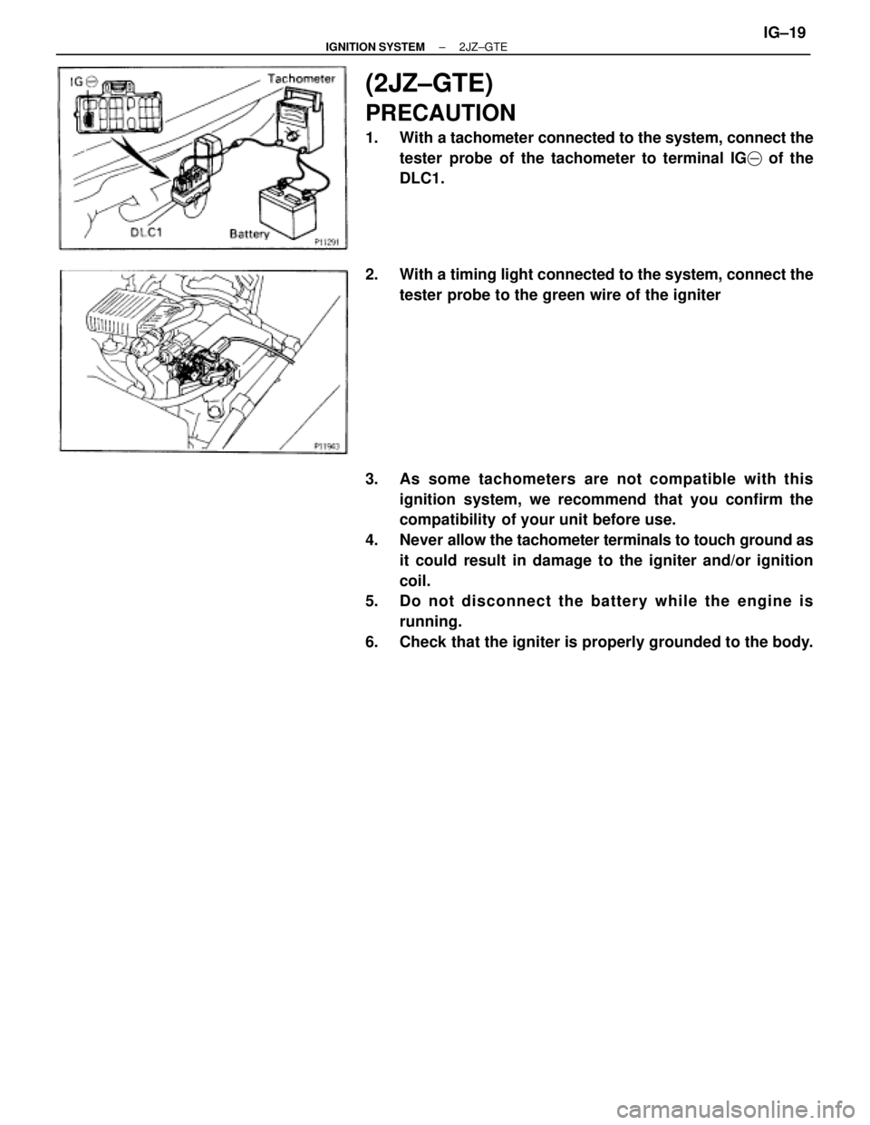
(2JZ±GTE)
PRECAUTION
1. With a tachometer connected to the system, connect the
tester probe of the tachometer to terminal IG� of the
DLC1.
2. With a timing light connected to the system, connect the
tester probe to the green wire of the igniter
3. As some tachometers are not compatible with this
ignition system, we recommend that you confirm the
compatibility of your unit before use.
4. Never allow the tachometer terminals to touch ground as
it could result in damage to the igniter and/or ignition
coil.
5. Do not disconnect the battery while the engine is
running.
6. Check that the igniter is properly grounded to the body.
± IGNITION SYSTEM2JZ±GTEIG±19
Page 1183 of 2543
FOR VEHICLES EQUIPPED WITH
TRACTION CONTROL (TRAC) SYSTEM
When using a rear wheel two±wheel drum tester such as a
speedometer tester or chassis dynamometer, etc., or jacking
up the rear wheels and driving the wheels, always push in the
TRAC cut (ºTRAC OFFº) switch and turn the TRAC system
OFF.
CONFIRM TRAC SYSTEM IS OFF
1. Press the TRAC cut (ºTRAC OFFº) switch.
2. Check that the TRAC OFF indicator light comes on when the
TRAC system is turned off by the TRAC cut switch.
HINT: The TRAC indicator light should always operate right
after the engine is restarted.
3. Begin measurements.
4. Press the TRAC cut switch again to change the TRAC to
operative and check that the TRAC OFF indicator light goes
off.
HINT: The TRAC indicator light blinks when the TRAC system
is operative. IN±16
± INTRODUCTIONPRECAUTION
Page 1191 of 2543
![TOYOTA SUPRA 1995 Service Repair Manual [3] SYMPTOM SIMULATION
The most difficult case in troubleshooting is when there are no problem symptoms occurring. In such cases, a
thorough customer problem analysis must be carried out, then simula](/manual-img/14/57468/w960_57468-1190.png "TOYOTA SUPRA 1995 Service Repair Manual [3] SYMPTOM SIMULATION
The most difficult case in troubleshooting is when there are no problem symptoms occurring. In such cases, a
thorough customer problem analysis must be carried out, then simula")
[3] SYMPTOM SIMULATION
The most difficult case in troubleshooting is when there are no problem symptoms occurring. In such cases, a
thorough customer problem analysis must be carried out, then simulate the same or similar conditions and envi-
ronment in which the problem occurred in the customer's vehicle. No matter how much experience a technician
has, or how skilled he may be, if he proceeds to troubleshoot without confirming the problem symptoms he will
tend to overlook something important in the repair operation and make a wrong guess somewhere, which will
only lead to a standstill. For example, for a problem which only occurs when the engine is cold, or for a problem
which occurs due to vibration caused by the road during driving, etc., the problem can never be determined so
long as the symptoms are confirmed with the engine hot condition or the vehicle at a standstill. Since vibration,
heat or water penetration (moisture) are likely causes for problems which are difficult to reproduce, the symptom
simulation tests introduced here are effective measures in that the external causes are applied to the vehicle
in a stopped condition.
Important Points in the Symptom Simulation Test
In the symptom simulation test, the problem symptoms should of course be confirmed, but the problem area
or parts must also be found out. To do this, narrow down the possible problem circuits according to the symptoms
before starting this test and connect a tester beforehand. After that, carry out the symptom simulation test, judg-
ing whether the circuit being tested is defective or normal and also confirming the problem symptoms at the
same time. Refer to the matrix chart of problem symptoms for each system to narrow down the possible causes
of the symptom.
VIBRATION METHOD: When vibration seems to be the major cause.
CONNECTORS
Slightly shake the connector vertically and horizontally.
WIRE HARNESS
Slightly shake the connector vertically and horizontally
.
The connector joint, fulcrum of the vibration, and body
through portion are the major areas to be checked thor-
oughly.
PARTS AND SENSORS
Apply slight vibration with a finger to the part of the sen-
sor considered to be the problem cause and check if the
malfunction occurs.
HINT: Applying strong vibration to relays may result in
open relays. IN±24
± INTRODUCTIONHOW TO TROUBLESHOOT ECU CONTROLLED SYSTEMS

 Check that the timing marks of the camshaft timing pulleys
and No.4 timing belt cover are aligned.
If not, turn the crankshaft 1 revolution (360°) and align the
mark as above.
3. INSTALL DISTRIB")
 SYSTEM
When using a rear wheel two±wheel drum tester such as a
speedometer tester or chassis dynamometer, etc., or jacking
up the rear wheels and d")