Page 876 of 2543
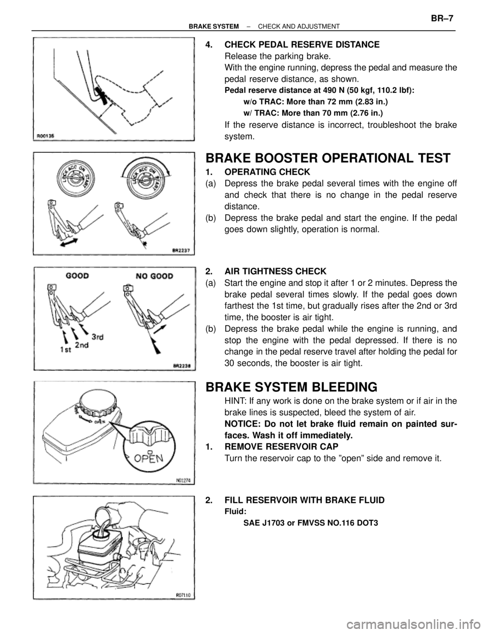
4. CHECK PEDAL RESERVE DISTANCE
Release the parking brake.
With the engine running, depress the pedal and measure the
pedal reserve distance, as shown.
Pedal reserve distance at 490 N (50 kgf, 110.2 lbf):
w/o TRAC: More than 72 mm (2.83 in.)
w/ TRAC: More than 70 mm (2.76 in.)
If the reserve distance is incorrect, troubleshoot the brake
system.
BRAKE BOOSTER OPERATIONAL TEST
1. OPERATING CHECK
(a) Depress the brake pedal several times with the engine off
and check that there is no change in the pedal reserve
distance.
(b) Depress the brake pedal and start the engine. If the pedal
goes down slightly, operation is normal.
2. AIR TIGHTNESS CHECK
(a) Start the engine and stop it after 1 or 2 minutes. Depress the
brake pedal several times slowly. If the pedal goes down
farthest the 1st time, but gradually rises after the 2nd or 3rd
time, the booster is air tight.
(b) Depress the brake pedal while the engine is running, and
stop the engine with the pedal depressed. If there is no
change in the pedal reserve travel after holding the pedal for
30 seconds, the booster is air tight.
BRAKE SYSTEM BLEEDING
HINT: If any work is done on the brake system or if air in the
brake lines is suspected, bleed the system of air.
NOTICE: Do not let brake fluid remain on painted sur-
faces. Wash it off immediately.
1. REMOVE RESERVOIR CAP
Turn the reservoir cap to the ºopenº side and remove it.
2. FILL RESERVOIR WITH BRAKE FLUID
Fluid:
SAE J1703 or FMVSS NO.116 DOT3
± BRAKE SYSTEMCHECK AND ADJUSTMENTBR±7
Page 931 of 2543
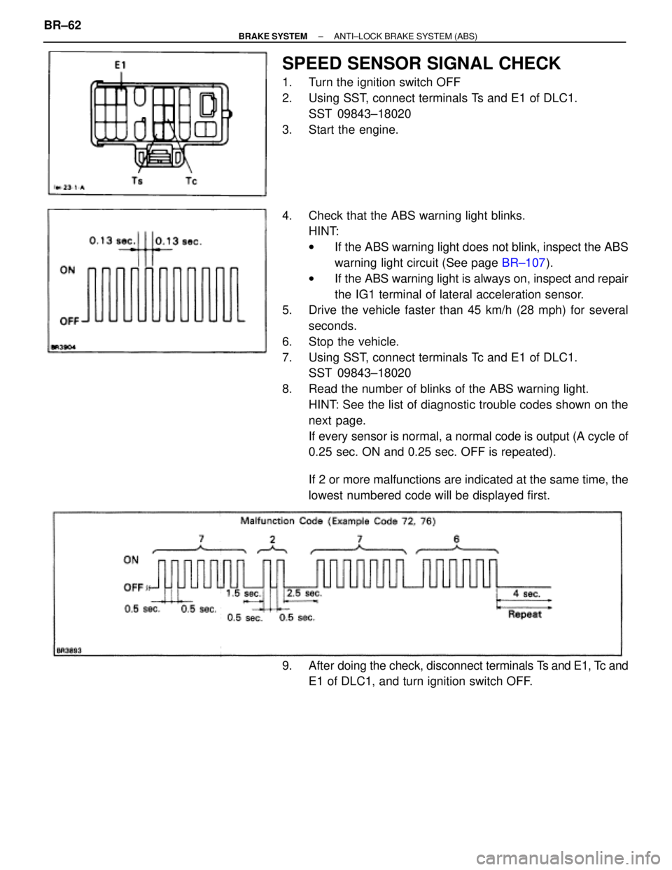
SPEED SENSOR SIGNAL CHECK
1. Turn the ignition switch OFF
2. Using SST, connect terminals Ts and E1 of DLC1.
SST 09843±18020
3. Start the engine.
4. Check that the ABS warning light blinks.
HINT:
wIf the ABS warning light does not blink, inspect the ABS
warning light circuit (See page BR±107).
wIf the ABS warning light is always on, inspect and repair
the IG1 terminal of lateral acceleration sensor.
5. Drive the vehicle faster than 45 km/h (28 mph) for several
seconds.
6. Stop the vehicle.
7. Using SST, connect terminals Tc and E1 of DLC1.
SST 09843±18020
8. Read the number of blinks of the ABS warning light.
HINT: See the list of diagnostic trouble codes shown on the
next page.
If every sensor is normal, a normal code is output (A cycle of
0.25 sec. ON and 0.25 sec. OFF is repeated).
If 2 or more malfunctions are indicated at the same time, the
lowest numbered code will be displayed first.
9. After doing the check, disconnect terminals Ts and E1, Tc and
E1 of DLC1, and turn ignition switch OFF. BR±62
± BRAKE SYSTEMANTI±LOCK BRAKE SYSTEM (ABS)
Page 983 of 2543
Ts Terminal Circuit
CIRCUIT DESCRIPTION
The sensor check circuit detects abnormalities in the speed sensor signal which cannot be detected with the
diagnostic trouble code check.
Connecting terminals Ts and E1 of the DLC1 in the engine compartment starts the check.
Check for open and short in harness and connector between ABS (&TRAC)
ECU and DLC1, DLC1 and body ground (See page IN±30).
Turn ignition switch ON.
Measure voltage between terminals Ts and E1 of
DLC1.
Voltage: 10 ± 14 V
If ABS warning light does not blink even
after Ts and E1 are connected, the ECU may
be defective.
Repair or replace harness or connector.
Check and replace ABS (& TRAC) ECU.
INSPECTION PROCEDURE.
BR±114± BRAKE SYSTEMANTI±LOCK BRAKE SYSTEM (ABS)
Page 997 of 2543
BR±134
BR±137
BR±137
BR±138
BR±138
BR±138
BR±138
BR±142
BR±145
BR±147
BR±149
BR±149
BR±152
BR±152
BR±155
BR±156
BR±157
Open or short in sub±throttle actuator circuit
Step motor does not move to a position decided by ECU
Sub±throttle valve does not move even when the sub±throttle
valve is controlled to fully open position by ECU
Right front wheel speed sensor signal malfunction
Left front wheel speed sensor signal malfunction
Right rear wheel speed sensor signal malfunction
Left rear wheel speed sensor signal malfunction
Low battery positive voltage or abnormally high battery
positive voltage
Malfunction in ABS or TRAC (BRAKE) control system
Open or short in NE signal circuit
Main throttle position sensor circuit malfunction
Open or short in main throttle position sensor circuit
Sub±throttle position sensor circuit malfunction
Open or short in sub±throttle position sensor circuit
Engine & ECT system malfunction
ECM communication circuit malfunction
ABS & TRAC ECU communication circuit malfunction
Malfunction in TRAC ECU
DiagnosisCodeTRAC Indicator Light
Blinking PatternSee page
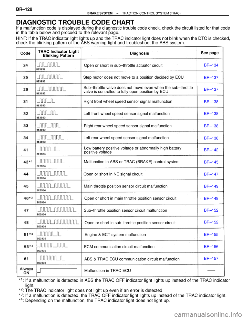
DIAGNOSTIC TROUBLE CODE CHART
If a malfunction code is displayed during the diagnostic trouble code check, check the circuit listed for that code
in the table below and proceed to the relevant page.
HINT: If the TRAC indicator light lights up and the TRAC indicator light does not blink when the DTC is checked,
check the blinking pattern of the ABS warning light and troubleshoot the ABS system.
*
1: If a malfunction is detected in ABS the TRAC OFF indicator light lights up instead of the TRAC indicator
light.
*
2: The TRAC indicator light does not light up even if an error is detected
*3: If a malfunction is detected, the TRAC OFF indicator light lights up instead of the TRAC indicator light.
*4: Depending on the malfunction, the TRAC indicator light does not light up. BR±128
± BRAKE SYSTEMTRACTION CONTROL SYSTEM (TRAC)
Page 1024 of 2543
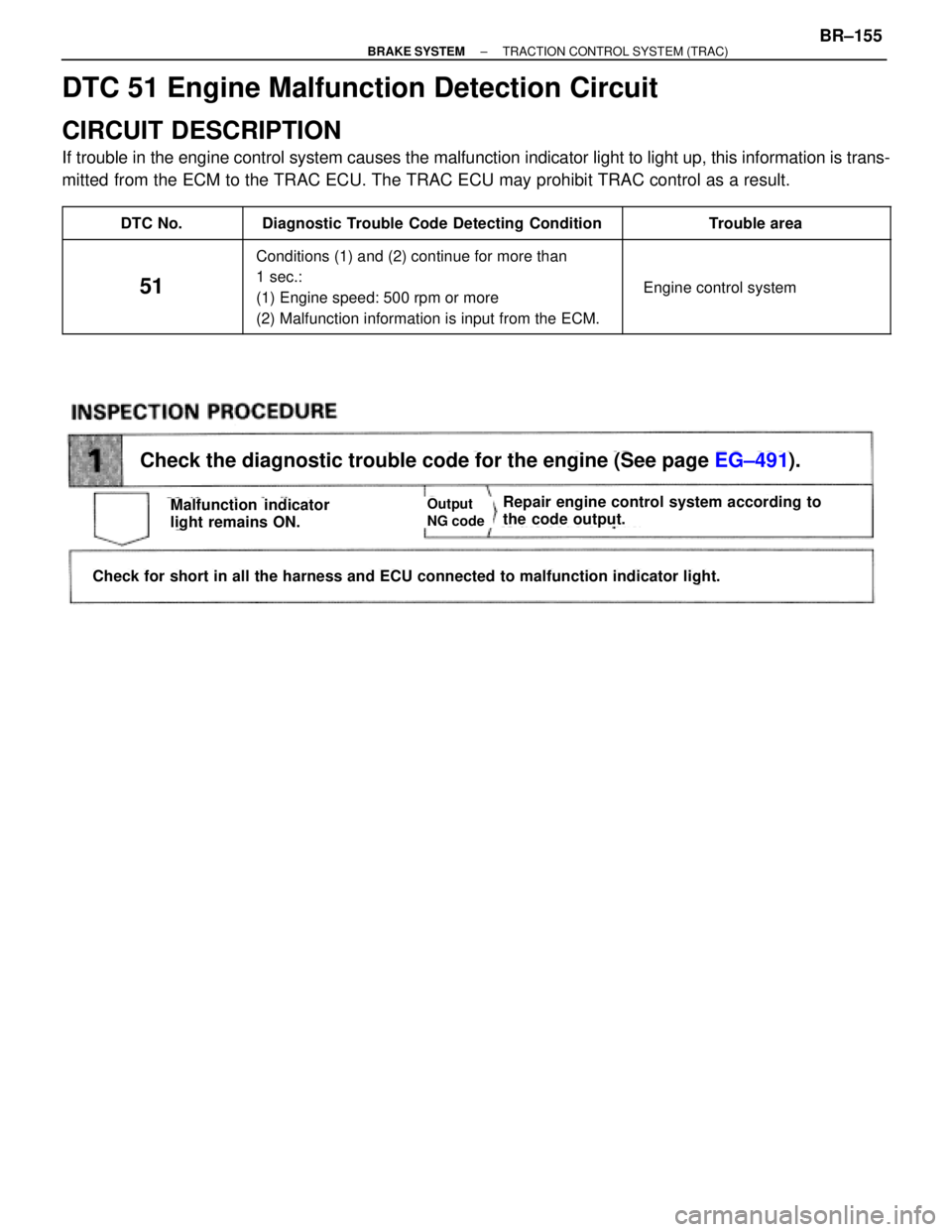
Check the diagnostic trouble code for the engine (See page EG±491).
Check for short in all the harness and ECU connected to malfunction indicator light.
Repair engine control system according to
the code output.Malfunction indicator
light remains ON.Output
NG code
DTC 51 Engine Malfunction Detection Circuit
CIRCUIT DESCRIPTION
If trouble in the engine control system causes the malfunction indicator light to light up, this information is trans-
mitted from the ECM to the TRAC ECU. The TRAC ECU may prohibit TRAC control as a result.
��������� �
��������DTC No.����������������� �
����������������Diagnostic Trouble Code Detecting Condition������������ �
�����������Trouble area��������� �
�������� �
�������� �
�������� �
��������
51
����������������� �
���������������� �
���������������� �
���������������� �
����������������
Conditions (1) and (2) continue for more than
1 sec.:
(1) Engine speed: 500 rpm or more
(2) Malfunction information is input from the ECM.
������������ �
����������� �
����������� �
����������� �
�����������
� Engine control system
± BRAKE SYSTEMTRACTION CONTROL SYSTEM (TRAC)BR±155
Page 1025 of 2543
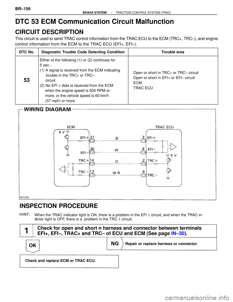
(See page IN±30).
Check for open and short n harness and connector between terminals
EFI+, EFI±, TRAC+ and TRC± of ECU and ECM (See page IN±30).
When the TRAC indicator light is ON, there is a problem in the EFI + circuit, and when the TRAC in-
dictor light is OFF, there is a problem in the TRC + circuit.
Repair or replace harness or connector.
Check and replace ECM or TRAC ECU.
INSPECTION PROCEDURE
DTC 53 ECM Communication Circuit Malfunction
CIRCUIT DESCRIPTION
This circuit is used to send TRAC control information from the TRAC ECU to the ECM (TRC+, TRC±), and engine
control information from the ECM to the TRAC ECU (EFI+, EFI±).
����� �����DTC No.���������������� ����������������Diagnostic Trouble Code Detecting Condition����������������� �����������������Trouble area
����� �
���� �
���� �
���� �
���� �
���� �
���� �
���� �����
53
���������������� �
��������������� �
��������������� �
��������������� �
��������������� �
��������������� �
��������������� �
��������������� ����������������
Either of the following (1) or (2) continues for
5 sec.:
(1) A signal is received from the ECM indicating
trouble in the TRC+ or TRC±
circuit.
(2) No EFI + data is received from the ECM
when the engine speed is 500 RPM or
more, or the vehicle speed is 60 km/h
(37 mph) or more.����������������� �
���������������� �
���������������� �
���������������� �
���������������� �
���������������� �
���������������� �
���������������� �����������������
� Open or short in TRC+ or TRC± circuit
� Open or short in EFI+ or EFI± circuit
� ECM
� TRAC ECU
BR±156± BRAKE SYSTEMTRACTION CONTROL SYSTEM (TRAC)
Page 1042 of 2543
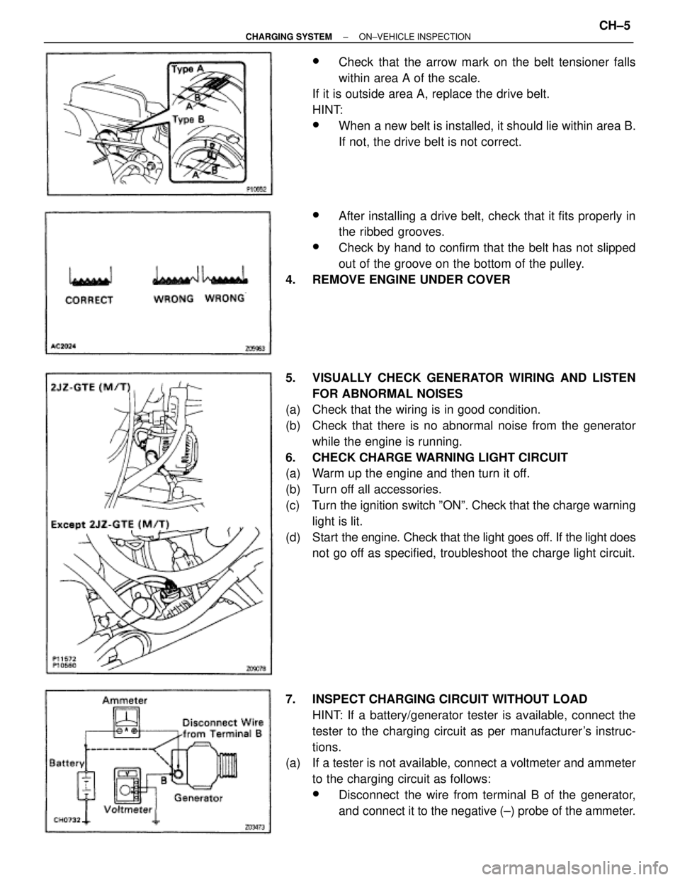
wCheck that the arrow mark on the belt tensioner falls
within area A of the scale.
If it is outside area A, replace the drive belt.
HINT:
wWhen a new belt is installed, it should lie within area B.
If not, the drive belt is not correct.
wAfter installing a drive belt, check that it fits properly in
the ribbed grooves.
wCheck by hand to confirm that the belt has not slipped
out of the groove on the bottom of the pulley.
4. REMOVE ENGINE UNDER COVER
5. VISUALLY CHECK GENERATOR WIRING AND LISTEN
FOR ABNORMAL NOISES
(a) Check that the wiring is in good condition.
(b) Check that there is no abnormal noise from the generator
while the engine is running.
6. CHECK CHARGE WARNING LIGHT CIRCUIT
(a) Warm up the engine and then turn it off.
(b) Turn off all accessories.
(c) Turn the ignition switch ºONº. Check that the charge warning
light is lit.
(d) Start the engine. Check that the light goes off. If the light does
not go off as specified, troubleshoot the charge light circuit.
7. INSPECT CHARGING CIRCUIT WITHOUT LOAD
HINT: If a battery/generator tester is available, connect the
tester to the charging circuit as per manufacturer's instruc-
tions.
(a) If a tester is not available, connect a voltmeter and ammeter
to the charging circuit as follows:
wDisconnect the wire from terminal B of the generator,
and connect it to the negative (±) probe of the ammeter.
± CHARGING SYSTEMON±VEHICLE INSPECTIONCH±5
Page 1043 of 2543
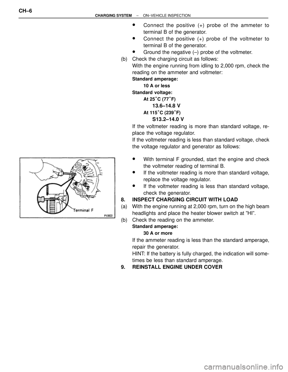
wConnect the positive (+) probe of the ammeter to
terminal B of the generator.
wConnect the positive (+) probe of the voltmeter to
terminal B of the generator.
wGround the negative (±) probe of the voltmeter.
(b) Check the charging circuit as follows:
With the engine running from idling to 2,000 rpm, check the
reading on the ammeter and voltmeter:
Standard amperage:
10 A or less
Standard voltage:
At 25°C (77°F)
13.6±14.8 V
At 115°C (239°F)
S13.2±14.0 V
If the voltmeter reading is more than standard voltage, re-
place the voltage regulator.
If the voltmeter reading is less than standard voltage, check
the voltage regulator and generator as follows:
wWith terminal F grounded, start the engine and check
the voltmeter reading of terminal B.
wIf the voltmeter reading is more than standard voltage,
replace the voltage regulator.
wIf the voltmeter reading is less than standard voltage,
check the generator.
8. INSPECT CHARGING CIRCUIT WITH LOAD
(a) With the engine running at 2,000 rpm, turn on the high beam
headlights and place the heater blower switch at ºHIº.
(b) Check the reading on the ammeter.
Standard amperage:
30 A or more
If the ammeter reading is less than the standard amperage,
repair the generator.
HINT: If the battery is fully charged, the indication will some-
times be less than standard amperage.
9. REINSTALL ENGINE UNDER COVER CH±6
± CHARGING SYSTEMON±VEHICLE INSPECTION