Page 1524 of 2543
(g) Remove the 5 bolts, nut, air intake chamber and 2 gaskets.
Torque: 27 NVm (270 kgfVcm, 20 ftVlbf)
INSTALLATION HINT: Install a new gasket to the air intake
chamber, facing the protrusion rearward.
INTAKE AIR CONTROL VALVE
INSPECTION
INSPECT INTAKE AIR CONTROL VALVE
(a) With 53.3 kPa (400 mmHg, 15.75 in.Hg) of vacuum applied
to the actuator, check that the actuator rod moves.
If operation is not as specified, turn the adjusting screw.
(b) 1 minute after applying the vacuum in (a), check that the
actuator rod does not return. EG±234
± ENGINESFI SYSTEM (2JZ±GE)
Page 1525 of 2543
EFI MAIN RELAY
EFI MAIN RELAY INSPECTION
1. REMOVE EFI MAIN RELAY
LOCATION: In the engine compartment relay box.
2. INSPECT EFI MAIN RELAY
A. Inspect relay continuity
(a) Using an ohmmeter, check that there is continuity between
terminals 1 and 2.
(b) Check that there is no continuity between terminals 3 and 5.
If continuity is not as specified, replace the relay.
B. Inspect relay operation
(a) Apply battery voltage across terminals 1 and 2.
(b) Using an ohmmeter, check that there is continuity between
terminals 3 and 5.
If operation is not as specified, replace the relay.
3. REINSTALL EFI MAIN RELAY
± ENGINESFI SYSTEM (2JZ±GE)EG±235
Page 1526 of 2543
VSV FOR ACIS
COMPONENTS FOR REMOVAL AND
INSTALLATION
VSV INSPECTION
1. REMOVE VSV
2. INSPECT VSV
A. Inspect VSV for open circuit
Using an ohmmeter, check that there is continuity between
the terminals.
Resistance:
At 205C (685F) 38.5±44.5 �
If there is no continuity, replace the VSV.
B. Inspect VSV for ground
Using an ohmmeter, check that there is no continuity be-
tween each terminal and the body.
If there is continuity, replace the VSV. EG±236
± ENGINESFI SYSTEM (2JZ±GE)
Page 1527 of 2543
C. Inspect VSV operation
(a) Check that air flows from port E to the filter.
(b) Apply battery voltage across the terminals.
(c) Check that air flows from port E to F.
If operation is not as specified, replace the VSV.
3. REINSTALL VSV
VSV FOR FUEL PRESSURE CONTROL
(California only)
COMPONENTS FOR REMOVAL AND
INSTALLATION
± ENGINESFI SYSTEM (2JZ±GE)EG±237
Page 1528 of 2543
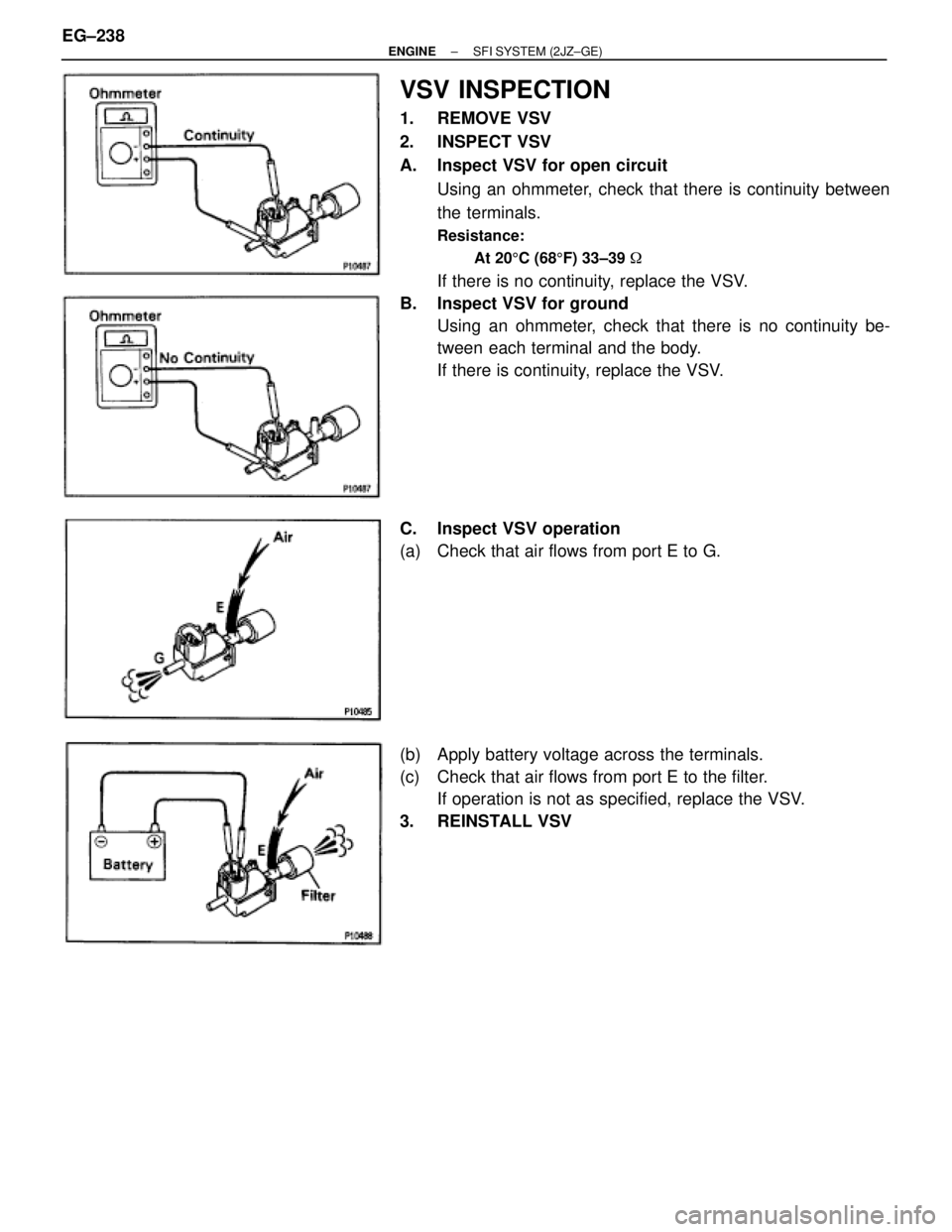
VSV INSPECTION
1. REMOVE VSV
2. INSPECT VSV
A. Inspect VSV for open circuit
Using an ohmmeter, check that there is continuity between
the terminals.
Resistance:
At 205C (685F) 33±39 �
If there is no continuity, replace the VSV.
B. Inspect VSV for ground
Using an ohmmeter, check that there is no continuity be-
tween each terminal and the body.
If there is continuity, replace the VSV.
C. Inspect VSV operation
(a) Check that air flows from port E to G.
(b) Apply battery voltage across the terminals.
(c) Check that air flows from port E to the filter.
If operation is not as specified, replace the VSV.
3. REINSTALL VSV EG±238
± ENGINESFI SYSTEM (2JZ±GE)
Page 1529 of 2543
VSV FOR EVAP
COMPONENTS FOR REMOVAL AND
INSTALLATION
VSV INSPECTION
1. REMOVE VSV
2. INSPECT VSV
A. Inspect VSV for open circuit
Using an ohmmeter, check that there is continuity between
the terminals.
Resistance:
At 205C (685F) 27±33 �
If there is no continuity, replace the VSV.
B. Inspect VSV for ground
Using an ohmmeter, check that there is no continuity be-
tween each terminal and the body.
If there is continuity, replace the VSV.
± ENGINESFI SYSTEM (2JZ±GE)EG±239
Page 1530 of 2543
C. Inspect VSV operation
(a) Check that air does not flow from port E to F.
(b) Apply battery voltage across the terminals.
(c) Check that air flows from port E to F.
If operation is not as specified, replace the VSV.
3. REINSTALL VSV
VSV FOR EGR
COMPONENTS FOR REMOVAL AND
INSTALLATION
EG±240± ENGINESFI SYSTEM (2JZ±GE)
Page 1531 of 2543
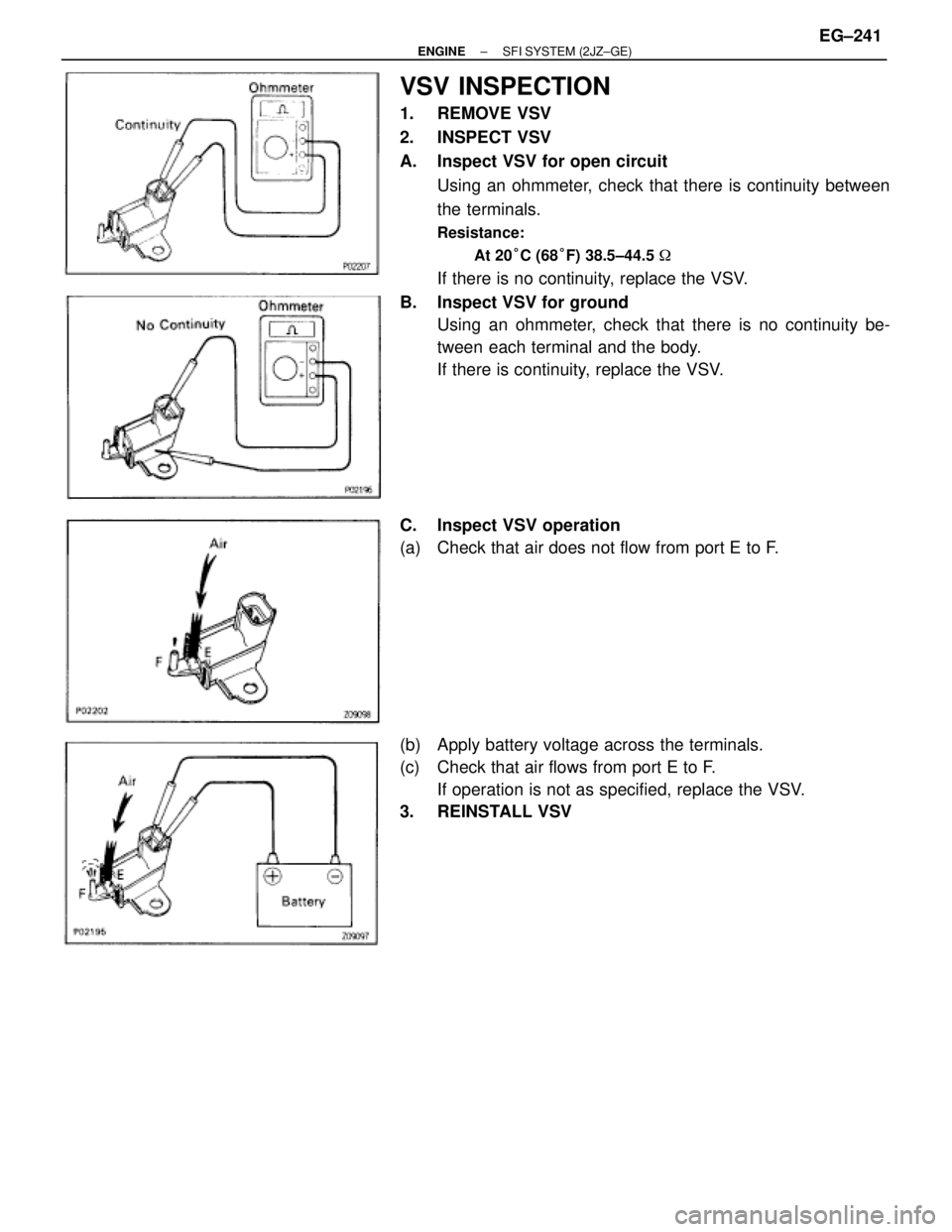
VSV INSPECTION
1. REMOVE VSV
2. INSPECT VSV
A. Inspect VSV for open circuit
Using an ohmmeter, check that there is continuity between
the terminals.
Resistance:
At 20°C (68°F) 38.5±44.5 �
If there is no continuity, replace the VSV.
B. Inspect VSV for ground
Using an ohmmeter, check that there is no continuity be-
tween each terminal and the body.
If there is continuity, replace the VSV.
C. Inspect VSV operation
(a) Check that air does not flow from port E to F.
(b) Apply battery voltage across the terminals.
(c) Check that air flows from port E to F.
If operation is not as specified, replace the VSV.
3. REINSTALL VSV
± ENGINESFI SYSTEM (2JZ±GE)EG±241
 Remove the 5 bolts, nut, air intake chamber and 2 gaskets.
Torque: 27 NVm (270 kgfVcm, 20 ftVlbf)
INSTALLATION HINT: Install a new gasket to the air intake
chamber, facing the protrusion rearward")
 Using an ohmmeter, check")

 Check that air flows from port E to the filter.
(b) Apply battery voltage across the terminals.
(c) Check that air flows from port E to F.
If operation is not as speci")

 Check that air does not flow from port E to F.
(b) Apply battery voltage across the terminals.
(c) Check that air flows from port E to F.
If operation is not as specif")