Page 1780 of 2543
INSPECTION PROCEDURES [P] Preparation [C] Check
Does SRS warning light turn off?
(1) Turn ignition switch to LOCK.
(2) Disconnect negative (±) terminal cable from the
battery, and wait at least 90 seconds.
(3) Disconnect center airbag sensor assembly
connector.
(4) Connect negative (±) terminal cable to battery.
Check operation of SRS warning light.
Replace center airbag sensor assembly.
Check SRS warning light circuit or terminal AB cir-
cuit of DLC1 or DLC2.
± SUPPLEMENTAL RESTRAINT SYSTEMTROUBLESHOOTINGRS±97
Page 1781 of 2543
Tc Terminal Circuit
CIRCUIT DESCRIPTION
By connecting terminals Tc and E1 of the DLC1 or DLC2, the center airbag sensor assembly is set in the diagnos-
tic trouble code output mode. The diagnostic trouble codes are displayed by the blinking of the SRS warning
light.
RS±98± SUPPLEMENTAL RESTRAINT SYSTEMTROUBLESHOOTING
Page 1783 of 2543
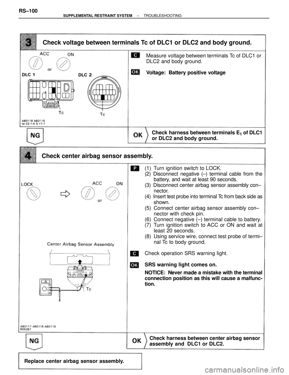
Check voltage between terminals Tc of DLC1 or DLC2 and body ground.
Measure voltage between terminals Tc of DLC1 or
DLC2 and body ground.
Voltage: Battery positive voltage
Check harness between terminals E1 of DLC1
or DLC2 and body ground.
Check center airbag sensor assembly.
(1) Turn ignition switch to LOCK.
(2) Disconnect negative (±) terminal cable from the
battery, and wait at least 90 seconds.
(3) Disconnect center airbag sensor assembly con±
nector.
(4) Insert test probe into terminal Tc from back side as
shown.
(5) Connect center airbag sensor assembly con±
nector with check pin.
(6) Connect negative (±) terminal cable to battery.
(7) Turn ignition switch to ACC or ON and wait at
least 20 seconds.
(8) Using service wire, connect test probe of termi±
nal Tc to body ground.
Check operation SRS warning light.
SRS warning light comes on.
NOTICE: Never made a mistake with the terminal
connection position as this will cause a malfunc-
tion.
Check harness between center airbag sensor
assembly and DLC1 or DLC2.
Replace center airbag sensor assembly. RS±100
± SUPPLEMENTAL RESTRAINT SYSTEMTROUBLESHOOTING
Page 1784 of 2543
HINT: If the diagnostic trouble code is displayed without a DTC check procedure, perform the following trouble-
shooting.
Repair or replace harness or connector.
Check resistance between terminal Tc of center airbag sensor assembly
and body ground.
(1) Turn ignition switch to LOCK.
(2) Disconnect negative (±) terminal cable from the
battery, and wait at least 90 seconds.
(3) Disconnect center airbag sensor assembly con±
nector.
Check resistance between terminal Tc of center airbag
sensor assembly connector and body ground.
Resistance: 1 M� or Higher
Replace center airbag sensor assembly.
± SUPPLEMENTAL RESTRAINT SYSTEMTROUBLESHOOTINGRS±101
Page 1785 of 2543
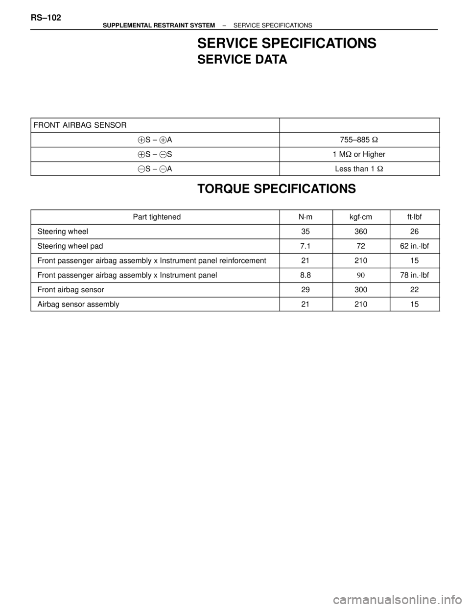
SERVICE SPECIFICATIONS
SERVICE DATA
���������������������� �
��������������������� ����������������������FRONT AIRBAG SENSOR
��������������� �
�������������� ���������������
���������������������� �����������������������S ± �A��������������� ���������������755±885 �
���������������������� �����������������������S ± �S��������������� ���������������1 M� or Higher
���������������������� �����������������������S ± �A��������������� ���������������Less than 1 �
TORQUE SPECIFICATIONS
���������������������� �
���������������������Part tightened������ �
�����NVm������ �
�����kgfVcm����� �
����ftVlbf���������������������� �
��������������������� ����������������������Steering wheel
������ �
����� ������35
������ �
����� ������360
����� �
���� �����26
���������������������� ����������������������Steering wheel pad������ ������7.1������ ������72����� �����62 in.Vlbf
���������������������� ����������������������Front passenger airbag assembly x Instrument panel reinforcement������ ������21������ ������210����� �����15
���������������������� ����������������������Front passenger airbag assembly x Instrument panel������ ������8.8������ ������90����� �����78 in.Vlbf���������������������� �
��������������������� ����������������������Front airbag sensor
������ �
����� ������29
������ �
����� ������300
����� �
���� �����22
���������������������� ����������������������Airbag sensor assembly������ ������21������ ������210����� �����15
RS±102± SUPPLEMENTAL RESTRAINT SYSTEMSERVICE SPECIFICATIONS
Page 1801 of 2543
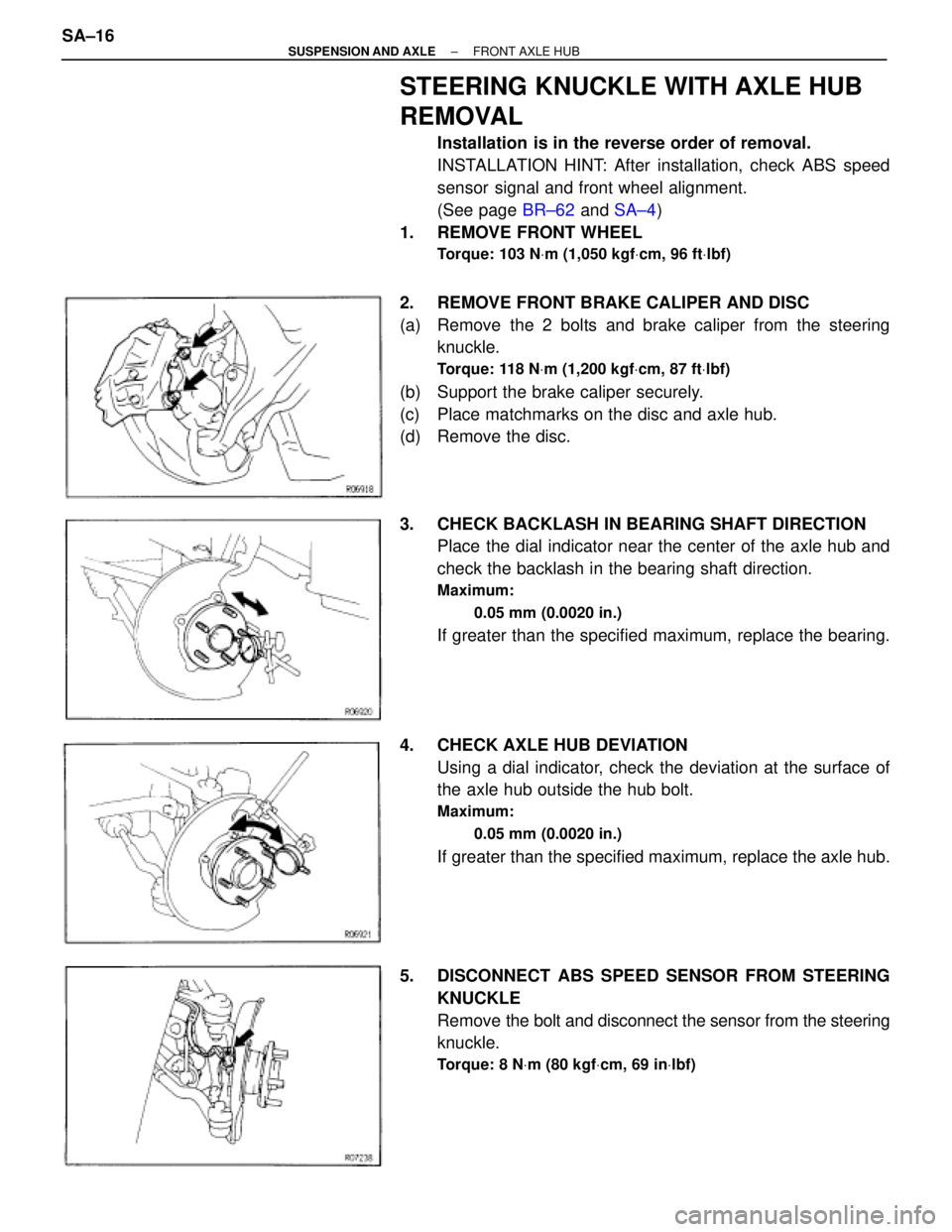
STEERING KNUCKLE WITH AXLE HUB
REMOVAL
Installation is in the reverse order of removal.
INSTALLATION HINT: After installation, check ABS speed
sensor signal and front wheel alignment.
(See page BR±62 and SA±4)
1. REMOVE FRONT WHEEL
Torque: 103 NVm (1,050 kgfVcm, 96 ftVlbf)
2. REMOVE FRONT BRAKE CALIPER AND DISC
(a) Remove the 2 bolts and brake caliper from the steering
knuckle.
Torque: 118 NVm (1,200 kgfVcm, 87 ftVlbf)
(b) Support the brake caliper securely.
(c) Place matchmarks on the disc and axle hub.
(d) Remove the disc.
3. CHECK BACKLASH IN BEARING SHAFT DIRECTION
Place the dial indicator near the center of the axle hub and
check the backlash in the bearing shaft direction.
Maximum:
0.05 mm (0.0020 in.)
If greater than the specified maximum, replace the bearing.
4. CHECK AXLE HUB DEVIATION
Using a dial indicator, check the deviation at the surface of
the axle hub outside the hub bolt.
Maximum:
0.05 mm (0.0020 in.)
If greater than the specified maximum, replace the axle hub.
5. DISCONNECT ABS SPEED SENSOR FROM STEERING
KNUCKLE
Remove the bolt and disconnect the sensor from the steering
knuckle.
Torque: 8 NVm (80 kgfVcm, 69 inVlbf)
SA±16± SUSPENSION AND AXLEFRONT AXLE HUB
Page 1802 of 2543
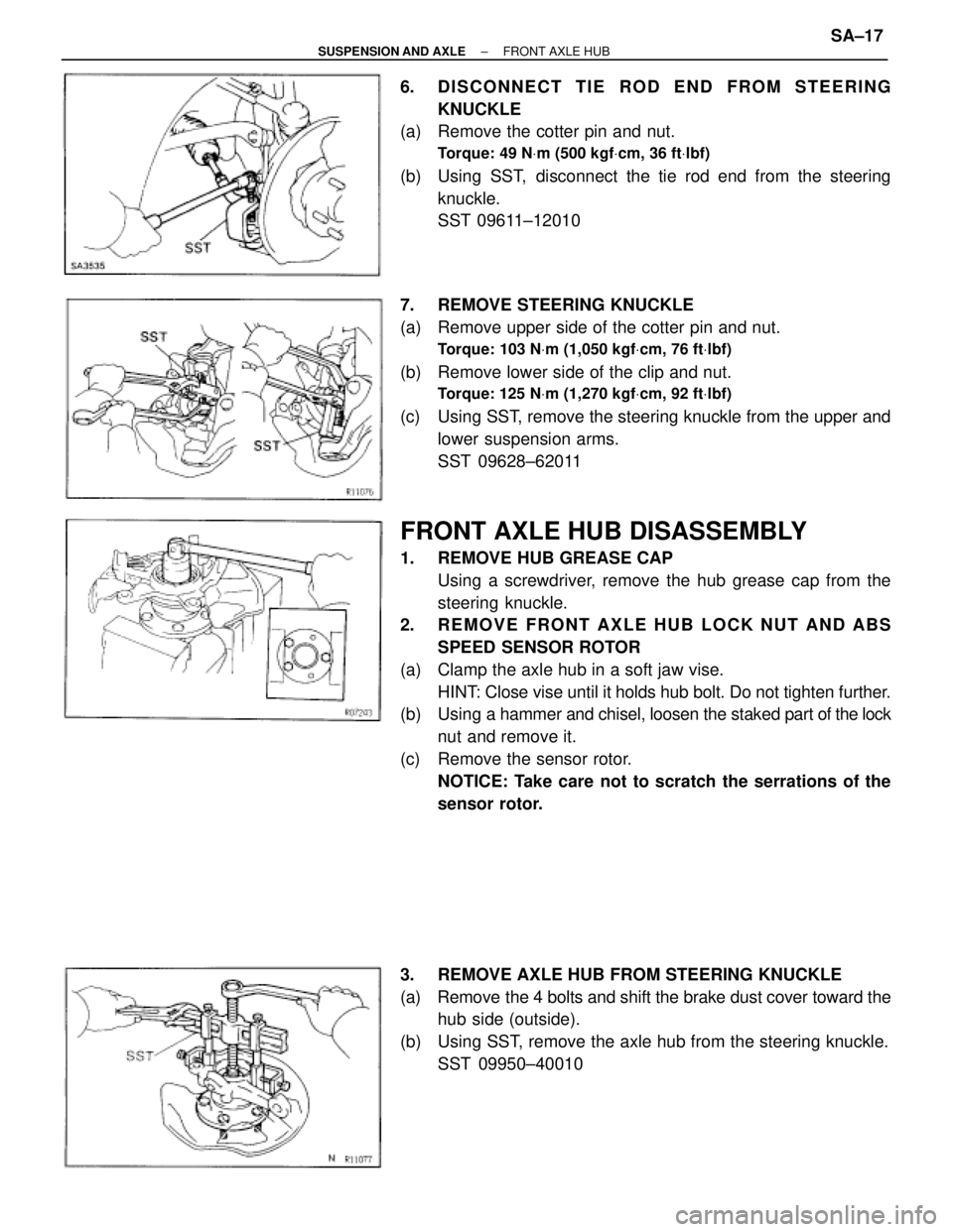
6. DISCONNECT TIE ROD END FROM STEERING
KNUCKLE
(a) Remove the cotter pin and nut.
Torque: 49 NVm (500 kgfVcm, 36 ftVlbf)
(b) Using SST, disconnect the tie rod end from the steering
knuckle.
SST 09611±12010
7. REMOVE STEERING KNUCKLE
(a) Remove upper side of the cotter pin and nut.
Torque: 103 NVm (1,050 kgfVcm, 76 ftVlbf)
(b) Remove lower side of the clip and nut.
Torque: 125 NVm (1,270 kgfVcm, 92 ftVlbf)
(c) Using SST, remove the steering knuckle from the upper and
lower suspension arms.
SST 09628±62011
FRONT AXLE HUB DISASSEMBLY
1. REMOVE HUB GREASE CAP
Using a screwdriver, remove the hub grease cap from the
steering knuckle.
2. REMOVE FRONT AXLE HUB LOCK NUT AND ABS
SPEED SENSOR ROTOR
(a) Clamp the axle hub in a soft jaw vise.
HINT: Close vise until it holds hub bolt. Do not tighten further.
(b) Using a hammer and chisel, loosen the staked part of the lock
nut and remove it.
(c) Remove the sensor rotor.
NOTICE: Take care not to scratch the serrations of the
sensor rotor.
3. REMOVE AXLE HUB FROM STEERING KNUCKLE
(a) Remove the 4 bolts and shift the brake dust cover toward the
hub side (outside).
(b) Using SST, remove the axle hub from the steering knuckle.
SST 09950±40010
± SUSPENSION AND AXLEFRONT AXLE HUBSA±17
Page 1804 of 2543
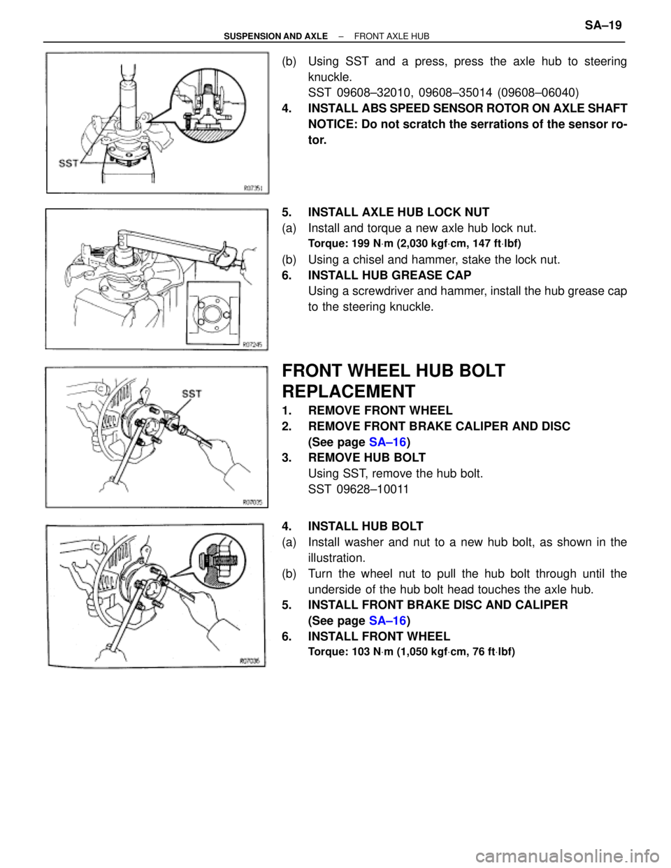
(b) Using SST and a press, press the axle hub to steering
knuckle.
SST 09608±32010, 09608±35014 (09608±06040)
4. INSTALL ABS SPEED SENSOR ROTOR ON AXLE SHAFT
NOTICE: Do not scratch the serrations of the sensor ro-
tor.
5. INSTALL AXLE HUB LOCK NUT
(a) Install and torque a new axle hub lock nut.
Torque: 199 NVm (2,030 kgfVcm, 147 ftVlbf)
(b) Using a chisel and hammer, stake the lock nut.
6. INSTALL HUB GREASE CAP
Using a screwdriver and hammer, install the hub grease cap
to the steering knuckle.
FRONT WHEEL HUB BOLT
REPLACEMENT
1. REMOVE FRONT WHEEL
2. REMOVE FRONT BRAKE CALIPER AND DISC
(See page SA±16)
3. REMOVE HUB BOLT
Using SST, remove the hub bolt.
SST 09628±10011
4. INSTALL HUB BOLT
(a) Install washer and nut to a new hub bolt, as shown in the
illustration.
(b) Turn the wheel nut to pull the hub bolt through until the
underside of the hub bolt head touches the axle hub.
5. INSTALL FRONT BRAKE DISC AND CALIPER
(See page SA±16)
6. INSTALL FRONT WHEEL
Torque: 103 NVm (1,050 kgfVcm, 76 ftVlbf)
± SUSPENSION AND AXLEFRONT AXLE HUBSA±19