Page 568 of 2543
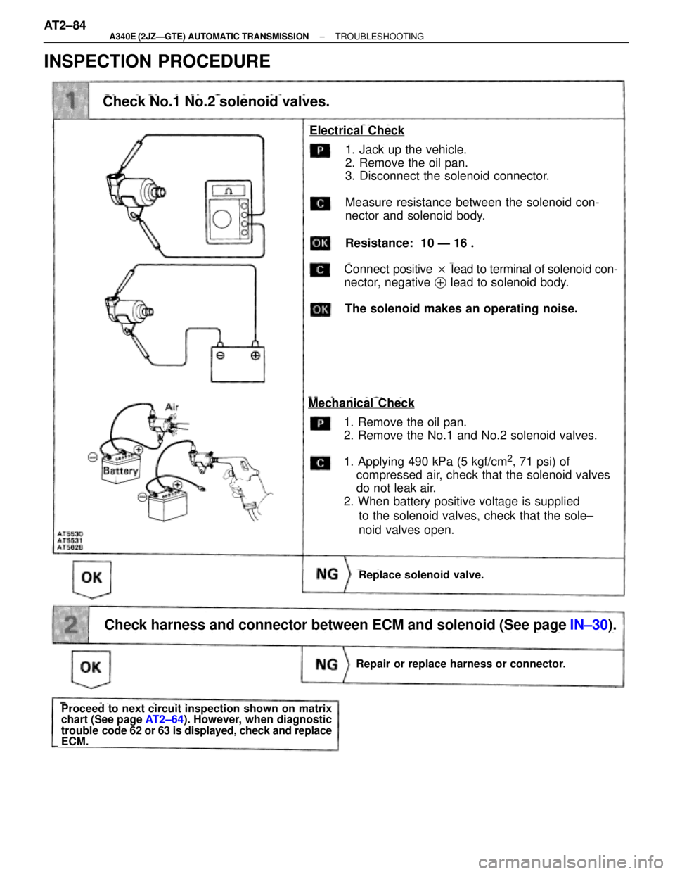
INSPECTION PROCEDURE
Check No.1 No.2 solenoid valves.
1. Jack up the vehicle.
2. Remove the oil pan.
3. Disconnect the solenoid connector.
Measure resistance between the solenoid con-
nector and solenoid body.
Resistance: 10 Ð 16 �
Replace solenoid valve.
Electrical Check
Connect positive � lead to terminal of solenoid con-
nector, negative � lead to solenoid body.
The solenoid makes an operating noise.
1. Remove the oil pan.
2. Remove the No.1 and No.2 solenoid valves.
1. Applying 490 kPa (5 kgf/cm
2, 71 psi) of
compressed air, check that the solenoid valves
do not leak air.
2. When battery positive voltage is supplied
to the solenoid valves, check that the sole±
noid valves open.
Mechanical Check
Repair or replace harness or connector.
Proceed to next circuit inspection shown on matrix
chart (See page AT2±64). However, when diagnostic
trouble code 62 or 63 is displayed, check and replace
ECM.
Check harness and connector between ECM and solenoid (See page IN±30).Check harness and connector between ECM and solenoid (See page IN±30).
AT2±84± A340E (2JZÐGTE) AUTOMATIC TRANSMISSIONTROUBLESHOOTING
Page 572 of 2543
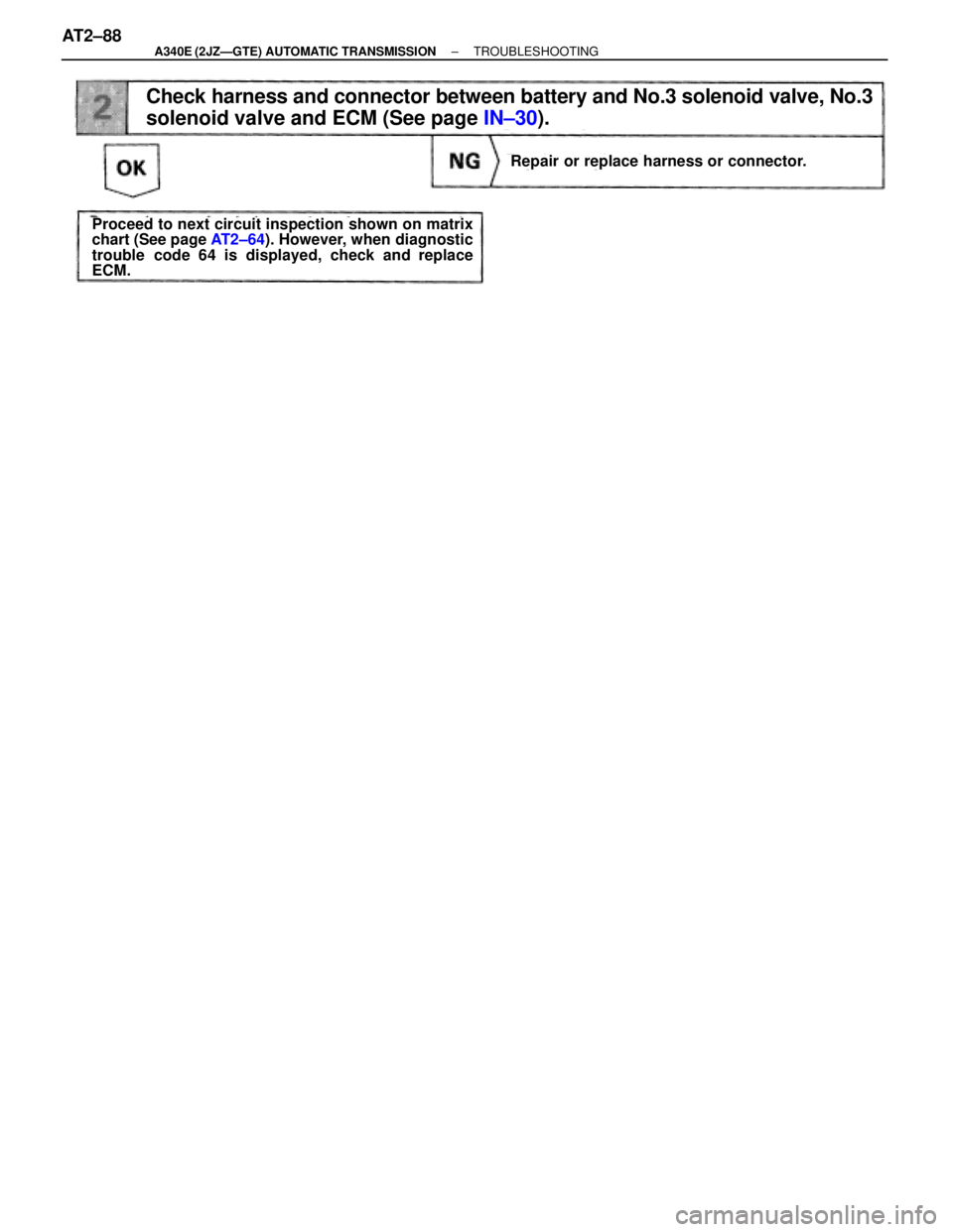
Check harness and connector between battery and No.3 solenoid valve, No.3
solenoid valve and ECM (See page IN±30).
Repair or replace harness or connector.
Proceed to next circuit inspection shown on matrix
chart (See page AT2±64). However, when diagnostic
trouble code 64 is displayed, check and replace
ECM.
AT2±88± A340E (2JZÐGTE) AUTOMATIC TRANSMISSIONTROUBLESHOOTING
Page 574 of 2543
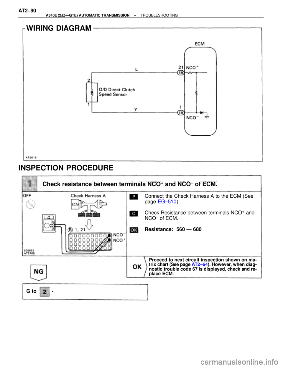
WIRING DIAGRAM
INSPECTION PROCEDURE
Check resistance between terminals NCO+ and NCO± of ECM.
Connect the Check Harness A to the ECM (See
page EG±510).
Check Resistance between terminals NCO
+ and
NCO± of ECM.
Resistance: 560 Ð 680 �
Proceed to next circuit inspection shown on ma-
trix chart (See page AT2±64). However, when diag-
nostic trouble code 67 is displayed, check and re-
place ECM.
G to� AT2±90
± A340E (2JZÐGTE) AUTOMATIC TRANSMISSIONTROUBLESHOOTING
Page 578 of 2543
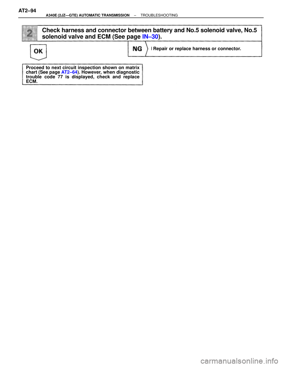
Repair or replace harness or connector.
Proceed to next circuit inspection shown on matrix
chart (See page AT2±64). However, when diagnostic
trouble code 77 is displayed, check and replace
ECM.
Check harness and connector between battery and No.5 solenoid valve, No.5
solenoid valve and ECM (See page IN±30).
AT2±94± A340E (2JZÐGTE) AUTOMATIC TRANSMISSIONTROUBLESHOOTING
Page 592 of 2543
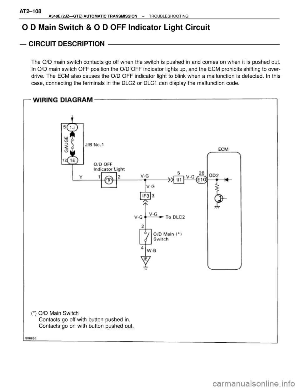
O D Main Switch & O D OFF Indicator Light Circuit
CIRCUIT DESCRIPTION
The O/D main switch contacts go off when the switch is pushed in and comes on when it is pushed out.
In O/D main switch OFF position the O/D OFF indicator lights up, and the ECM prohibits shifting to over-
drive. The ECM also causes the O/D OFF indicator light to blink when a malfunction is detected. In this
case, connecting the terminals in the DLC2 or DLC1 can display the malfunction code.
(*) O/D Main Switch
Contacts go off with button pushed in.
Contacts go on with button pushed out. AT2±108
± A340E (2JZÐGTE) AUTOMATIC TRANSMISSIONTROUBLESHOOTING
Page 597 of 2543
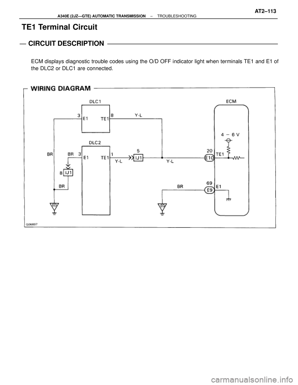
TE1 Terminal Circuit
CIRCUIT DESCRIPTION
ECM displays diagnostic trouble codes using the O/D OFF indicator light when terminals TE1 and E1 of
the DLC2 or DLC1 are connected.
± A340E (2JZÐGTE) AUTOMATIC TRANSMISSIONTROUBLESHOOTINGAT2±113
Page 686 of 2543

ANTI±THEFT SYSTEM
HINT: The words ºANTI±THEFT SYSTEMº are displayed on
the cassette tape slot cover.
For operation instructions for the anti±theft system, please
consult the audio system section in the Owner's Manual
(hereafter called O/M).
1. SETTING SYSTEM
The system is in operation once the customer has pushed the
required buttons and entered the customer±selected 3±digit
ID number.
(Refer to the O/M section, ºSetting the anti±theft systemº)
HINT:
w When the audio system is shipped the ID number has
not been input, so the anti±theft system is not in
operation.
w If the ID number has not been input, the audio system
remains the same as a normal audio system.
2. ANTI±THEFT SYSTEM OPERATION
If the normal electrical power source (connector or battery
terminal) is cut off, the audio system becomes inoperable,
even if the power supply resumes.
3. CANCELING SYSTEM
The ID number chosen by the customer is input to cancel the
anti±theft system.
(Refer to the O/M section, ºIf the system is activatedº)
HINT: To change or cancel the ID number, please refer to the
O/M section ºCancelling the systemº. BE±84
± BODY ELECTRICAL SYSTEMAUDIO SYSTEM
Page 713 of 2543
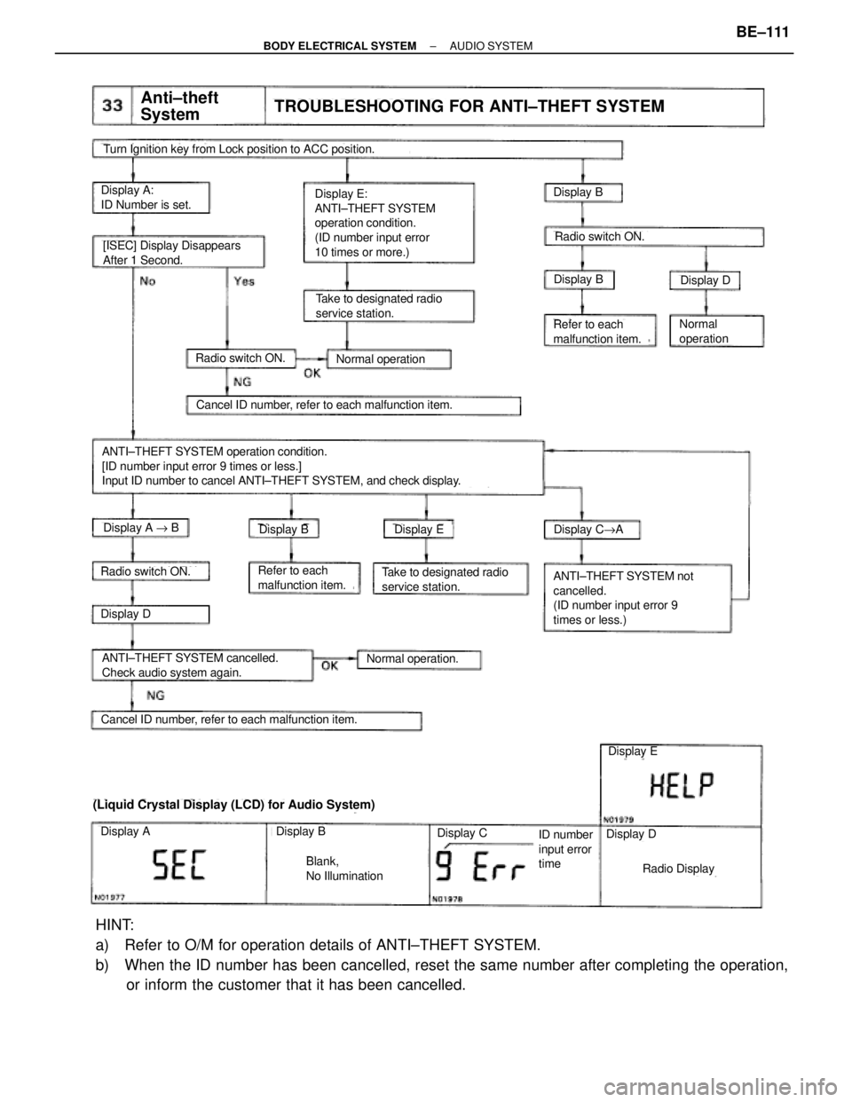
Display E:
ANTI±THEFT SYSTEM
operation condition.
(ID number input error
10 times or more.)Display A:
ID Number is set.Display B
Anti±theft
SystemTROUBLESHOOTING FOR ANTI±THEFT SYSTEM
Turn Ignition key from Lock position to ACC position.
Cancel ID number, refer to each malfunction item.
Take to designated radio
service station.
[ISEC] Display Disappears
After 1 Second.
Normal operation
Refer to each
malfunction item.
(Liquid Crystal Display (LCD) for Audio System)
Cancel ID number, refer to each malfunction item.
ANTI±THEFT SYSTEM operation condition.
[ID number input error 9 times or less.]
Input ID number to cancel ANTI±THEFT SYSTEM, and check display.
Radio switch ON.
ANTI±THEFT SYSTEM not
cancelled.
(ID number input error 9
times or less.)
ANTI±THEFT SYSTEM cancelled.
Check audio system again.
Radio Display
Display BDisplay D
Radio switch ON.
Display EDisplay C"ADisplay BDisplay A " B
Display D
Radio switch ON.Take to designated radio
service station.Refer to each
malfunction item.
Normal
operation
Normal operation.
ID number
input error
time
Blank,
No Illumination
Display B
Display E
Display DDisplay ADisplay C
HINT:
a) Refer to O/M for operation details of ANTI±THEFT SYSTEM.
b) When the ID number has been cancelled, reset the same number after completing the operation,
or inform the customer that it has been cancelled.
± BODY ELECTRICAL SYSTEMAUDIO SYSTEMBE±111