Page 1921 of 2543
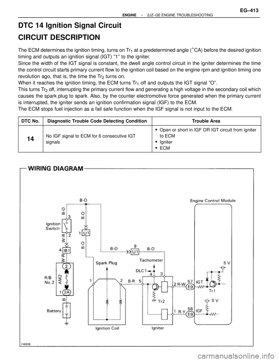
DTC 14 Ignition Signal Circuit
CIRCUIT DESCRIPTION
The ECM determines the ignition timing, turns on Tr1 at a predetermined angle (°CA) before the desired ignition
timing and outputs an ignition signal (IGT) º1º to the igniter.
Since the width of the IGT signal is constant, the dwell angle control circuit in the igniter determines the time
the control circuit starts primary current flow to the ignition coil based on the engine rpm and ignition timing one
revolution ago, that is, the time the Tr
2 turns on.
When it reaches the ignition timing, the ECM turns Tr
1 off and outputs the IGT signal ºOº.
This turns Tr
2 off, interrupting the primary current flow and generating a high voltage in the secondary coil which
causes the spark plug to spark. Also, by the counter electromotive force generated when the primary current
is interrupted, the igniter sends an ignition confirmation signal (IGF) to the ECM.
The ECM stops fuel injection as a fail safe function when the IGF signal is not input to the ECM.
����� �����DTC No.���������������� ����������������Diagnostic Trouble Code Detecting Condition����������������� �����������������Trouble Area����� �
���� �����
14
���������������� �
��������������� ���������������� No IGF signal to ECM for 6 consecutive IGT
����������������� �
���������������� ������������������Open or short in IGF OR IGT circuit from igniter
to ECM
����� �
���� �����
14���������������� �
��������������� ����������������
No IGF signal to ECM for 6 consecutive IGT
signals����������������� �
���������������� �����������������
to ECM
�Igniter
�ECM
± ENGINE2JZ±GE ENGINE TROUBLESHOOTINGEG±413
Page 1924 of 2543
Check ignition coil.
Disconnect ignition coil connector.
(1) Check primary coil.
Measure resistance between terminals of ignition coil
connector.
(2) Check secondary coil.
Measure resistance between terminal � of ignition coil
connector and high±tension terminal.
Repair or replace harness or connector.
Check for open and short in harness and connector between ignitioin switch
and ignition coil, ignition coil and igniter (See page
IN±30).
ªColdº is from Ð 10°C (14°F) to 50°C (122°F) and
ªHotº is from 50°C (122°F) to 100°C (212°F).
Replace ignition coil.
Replace igniter.
Resistance
Primary Coil
Secondary
Coil
EG±416± ENGINE2JZ±GE ENGINE TROUBLESHOOTING
Page 1946 of 2543
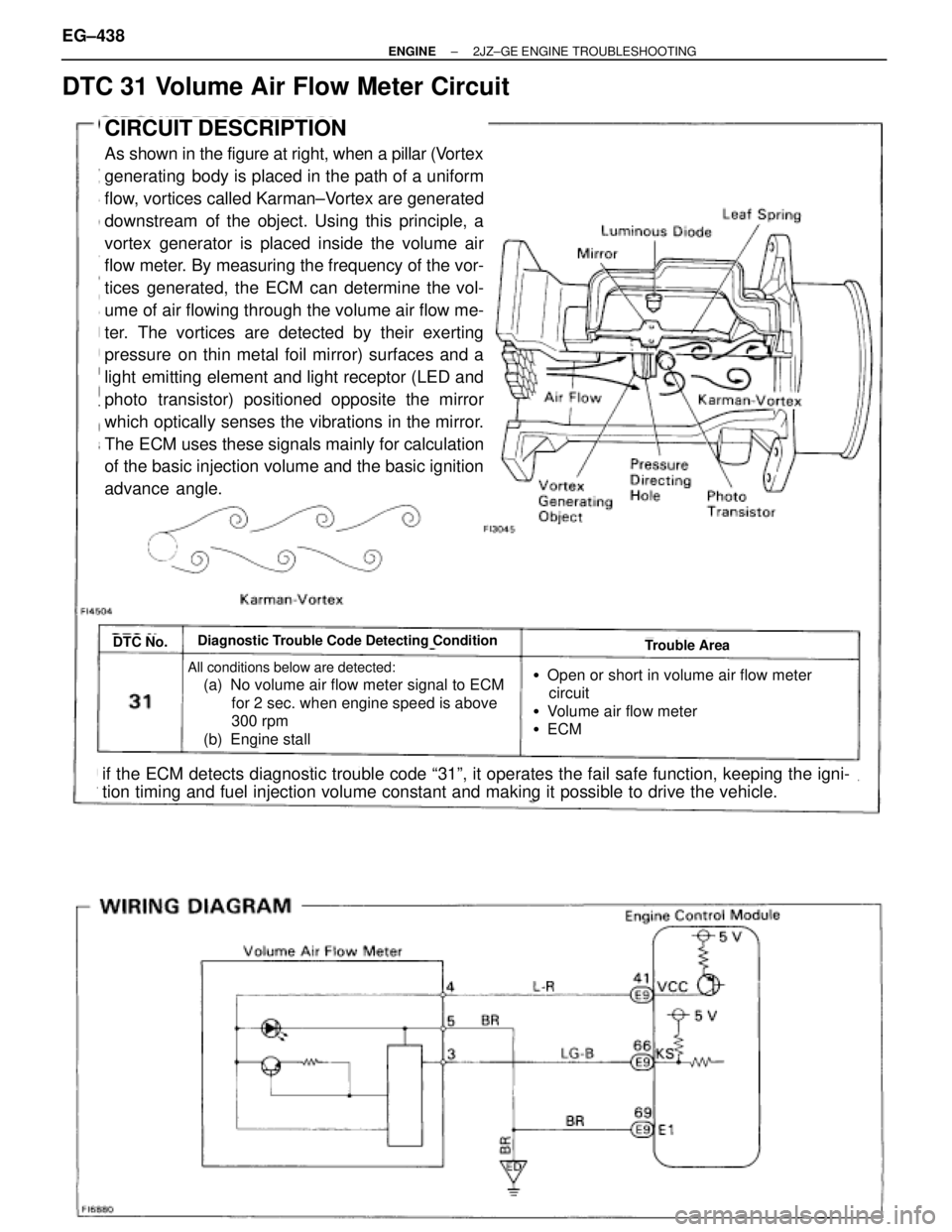
DTC 31 Volume Air Flow Meter Circuit
CIRCUIT DESCRIPTION
As shown in the figure at right, when a pillar (Vortex
generating body is placed in the path of a uniform
flow, vortices called Karman±Vortex are generated
downstream of the object. Using this principle, a
vortex generator is placed inside the volume air
flow meter. By measuring the frequency of the vor-
tices generated, the ECM can determine the vol-
ume of air flowing through the volume air flow me-
ter. The vortices are detected by their exerting
pressure on thin metal foil mirror) surfaces and a
light emitting element and light receptor (LED and
photo transistor) positioned opposite the mirror
which optically senses the vibrations in the mirror.
The ECM uses these signals mainly for calculation
of the basic injection volume and the basic ignition
advance angle.
DTC No.Diagnostic Trouble Code Detecting ConditionTrouble Area
All conditions below are detected:
(a) No volume air flow meter signal to ECM
for 2 sec. when engine speed is above
300 rpm
(b) Engine stall �Open or short in volume air flow meter
circuit
�Volume air flow meter
�ECM
if the ECM detects diagnostic trouble code ª31º, it operates the fail safe function, keeping the igni-
tion timing and fuel injection volume constant and making it possible to drive the vehicle. EG±438
± ENGINE2JZ±GE ENGINE TROUBLESHOOTING
Page 1973 of 2543
ECM Power Source Circuit
CIRCUIT DESCRIPTION
When the ignition switch is turned on, battery
voltage is applied to the terminals IGSW of the
ECM, and the main relay control circuit in the
ECM sends a signal to the terminal M±REL of the
ECM, switching on the main relay. This signal
causes current to flow to the coil, closing the con-
tacts of the main relay and supplying power to the
terminal +B of the ECM.
If the ignition switch is turned off, the ECM contin-
ues to switch on the main relay for a maximum of
2 seconds for the initial setting of the IAC valve.
± ENGINE2JZ±GE ENGINE TROUBLESHOOTINGEG±465
Page 1983 of 2543
CIRCUIT DESCRIPTION
The IAC valve is situated on the intake chamber. Intake
air bypassing the throttle valve is directed to the IAC
valve through a passage.
A step motor is built into the IAC valve. It consists of 4
coils, a magnetic rotor, valve shaft and valve.
When current flows to the coils due to signals from the
ECM, the rotor turns and moves the valve shaft forward
or backward, changing the clearance between the
valve and the valve seat.
In this way the intake air volume bypassing the throttle
valve is regulated, controlling the engine speed.
There are 125 possible positions to which the valve can
be opened.
�With the engine idling measure wave forms
between terminals ISC1, ISC2, ISC3, ISC4
and E01 of engine control module when
A/C switch ON or OFF.
HINT:
The correct waveforms are as shown.
INSPECTION USING OSCILLOSCOPE
IAC Valve Circuit
± ENGINE2JZ±GE ENGINE TROUBLESHOOTINGEG±475
Page 2013 of 2543
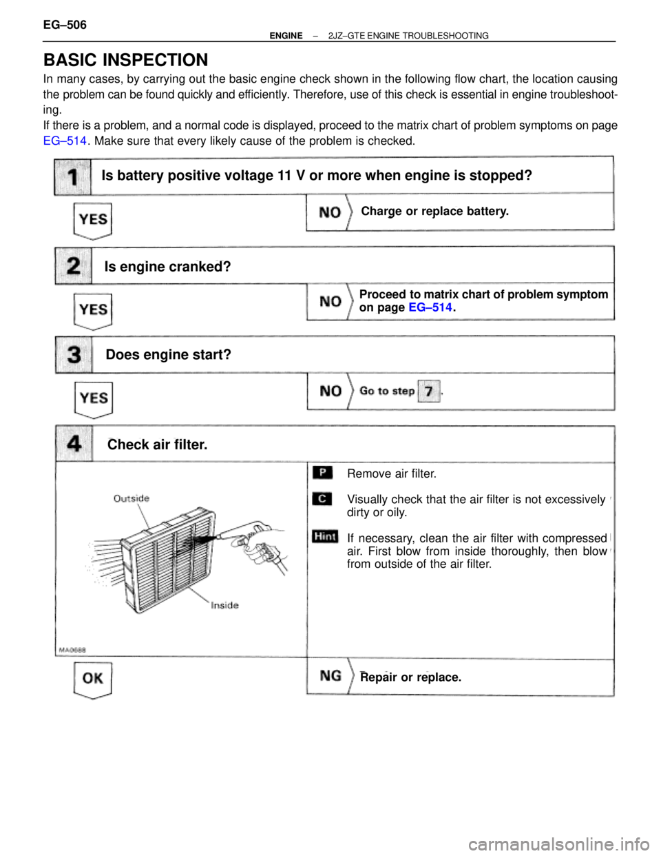
BASIC INSPECTION
In many cases, by carrying out the basic engine check shown in the following flow chart, the location causing
the problem can be found quickly and efficiently. Therefore, use of this check is essential in engine troubleshoot-
ing.
If there is a problem, and a normal code is displayed, proceed to the matrix chart of problem symptoms on page
EG±514. Make sure that every likely cause of the problem is checked.
Is battery positive voltage 11 V or more when engine is stopped?
Is engine cranked?
Does engine start?
Check air filter.
Charge or replace battery.
Proceed to matrix chart of problem symptom
on page EG±514.
Repair or replace.
Remove air filter.
Visually check that the air filter is not excessively
dirty or oily.
If necessary, clean the air filter with compressed
air. First blow from inside thoroughly, then blow
from outside of the air filter.
Charge or replace battery.
Is battery positive voltage 11 V or more when engine is stopped?
EG±506± ENGINE2JZ±GTE ENGINE TROUBLESHOOTING
Page 2014 of 2543
(See page EG±20)
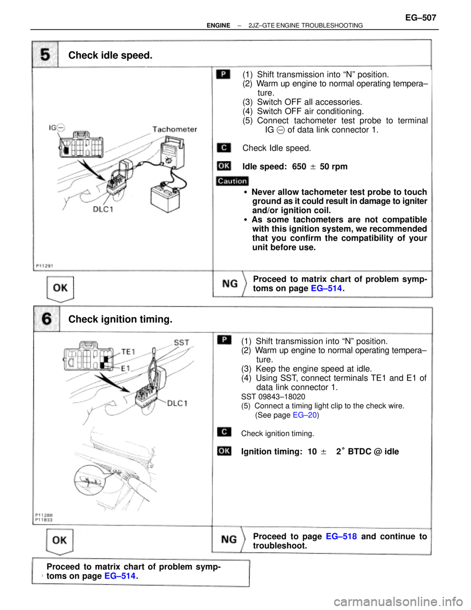
Check idle speed.
Proceed to matrix chart of problem symp-
toms on page EG±514.
(1) Shift transmission into ªNº position.
(2) Warm up engine to normal operating tempera±
ture.
(3) Switch OFF all accessories.
(4) Switch OFF air conditioning.
(5) Connect tachometer test probe to terminal
IG� of data link connector 1.
Check Idle speed.
Idle speed: 650 � 50 rpm
�Never allow tachometer test probe to touch
ground as it could result in damage to igniter
and/or ignition coil.
�As some tachometers are not compatible
with this ignition system, we recommended
that you confirm the compatibility of your
unit before use.
Check ignition timing.
(1) Shift transmission into ªNº position.
(2) Warm up engine to normal operating tempera±
ture.
(3) Keep the engine speed at idle.
(4) Using SST, connect terminals TE1 and E1 of
data link connector 1.
SST 09843±18020
(5) Connect a timing light clip to the check wire.
(See page EG±20)
Check ignition timing.
Ignition timing: 10 ��2° BTDC @ idle
Proceed to matrix chart of problem symp-
toms on page EG±514.
Proceed to page EG±518 and continue to
troubleshoot.
± ENGINE2JZ±GTE ENGINE TROUBLESHOOTINGEG±507
Page 2015 of 2543
(See page
IG±26)
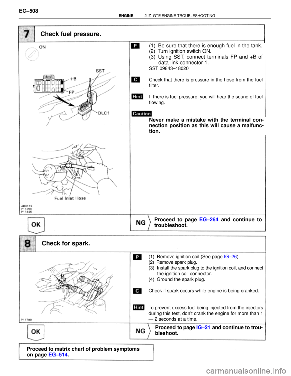
Check fuel pressure.
Proceed to page EG±264 and continue to
troubleshoot.
(1) Be sure that there is enough fuel in the tank.
(2) Turn ignition switch ON.
(3) Using SST, connect terminals FP and +B of
data link connector 1.
SST 09843±18020
Check that there is pressure in the hose from the fuel
filter.
If there is fuel pressure, you will hear the sound of fuel
flowing.
Never make a mistake with the terminal con-
nection position as this will cause a malfunc-
tion.
Check for spark.
Proceed to page IG±21 and continue to trou-
bleshoot.
Proceed to matrix chart of problem symptoms
on page EG±514.
(1) Remove ignition coil (See page IG±26)
(2) Remove spark plug.
(3) Install the spark plug to the ignition coil, and connect
the ignition coil connector.
(4) Ground the spark plug.
Check if spark occurs while engine is being cranked.
To prevent excess fuel being injected from the injectors
during this test, don't crank the engine for more than 1
Ð 2 seconds at a time.
EG±508± ENGINE2JZ±GTE ENGINE TROUBLESHOOTING