Page 1678 of 2248
�1
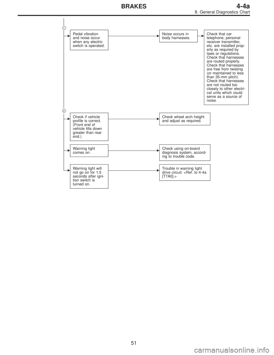
�Pedal vibration
and noise occur
when any electric
switch is operated.�Noise occurs in
body harnesses.�Check that car
telephone, personal
receiver transmitter,
etc. are installed prop-
erly as required by
laws or regulations.
Check that harnesses
are routed properly.
Check that harnesses
are free from twisting
(or maintained to less
than 35-mm pitch).
Check that harnesses
are not routed too
closely to other electri-
cal units which could
serve as a source of
noise.
�2
�Check if vehicle
profile is correct.
(Front end of
vehicle tilts down
greater than rear
end.)�Check wheel arch height
and adjust as required.
�Warning light
comes on.�Check using on-board
diagnosis system, accord-
ing to trouble code.
�Warning light will
not go on for 1.5
seconds after igni-
tion switch is
turned on.�Trouble in warning light
drive circuit.
[T7A0].>
51
4-4aBRAKES
8. General Diagnostics Chart
Page 1808 of 2248

11. General Diagnostics Table
��: Primary expected causes�: Secondary expected causes
Trouble conditions
SymptomsHydraulic
unit
Speed sensor
P valve
Master cylinder
Calipers and piston
Pad
Rotor
Hand brake
Piping
Mixture of air
Brake booster and check valve
Axle and wheel
Alignment
Play of pedal
Rough road surface
Semicylindrical road surface
Loose or worn suspension
Tire
Wrong connection and wiring
Stroke sensor Solenoid valve
Motor
Mount bush ABS function
Directional stability cannot be
obtained when braking.Vehicle turns to right or left.����������� ������������
Vehicle spins.�������������
Out-of-order brakesLong braking distance
��� ���������������
Brakes lock.������� � ��
Brakes drag.�����������������
Long pedal stroke� ���� �����
Abnormal vehicle pitching�� ������
Unstable braking force. One-
side brake refuses to work.����������� ����������
TCS function
When accelerating abruptly,
directional stability cannot be
obtained when traveling on a
slippery road surface.Vehicle moves unsteadily.������������������
Handle refuses to work.�������������
Handle loses control.���������� ���������
Bad acceleration, engine stall-
ing (In addition to the causes
listed here, check the ECM
specifications.)Engine stalls. Engine speed
fails to increase.�����������
Engine speed increases sud-
denly.��������������������
Vibration occurs and abnormal
noise is produced.
�When applying brakes abruptly.
�When accelerating abruptly.
�When driving on a slippery
road surface.Brake pedal heavily vibrates
when applying brakes.
�� � � �������
Loud hydraulic unit operating
noise��������
Noise is produced from front
of vehicle.���������������������
Noise is produced from rear of
vehicle.����������������
NOTE:
This list includes no engine failure and transmission failure.
127
4-4bBRAKES
11. General Diagnostics Table
Page 1875 of 2248
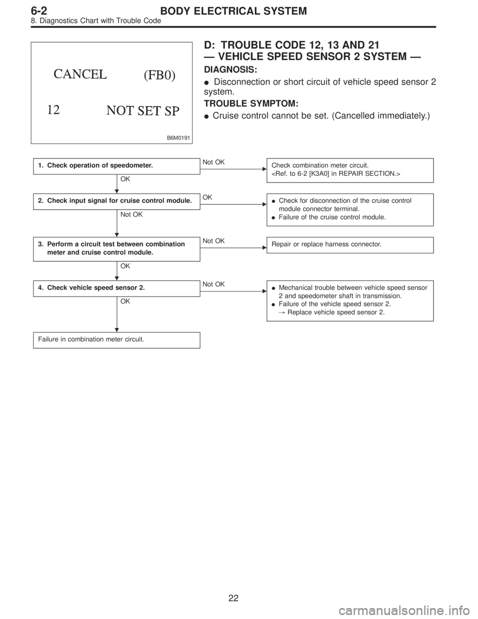
B6M0191
D: TROUBLE CODE 12, 13 AND 21
—VEHICLE SPEED SENSOR 2 SYSTEM—
DIAGNOSIS:
�Disconnection or short circuit of vehicle speed sensor 2
system.
TROUBLE SYMPTOM:
�Cruise control cannot be set. (Cancelled immediately.)
1. Check operation of speedometer.
OK
�Not OK
Check combination meter circuit.
2. Check input signal for cruise control module.
Not OK
�OK
�Check for disconnection of the cruise control
module connector terminal.
�Failure of the cruise control module.
3. Perform a circuit test between combination
meter and cruise control module.
OK
�Not OK
Repair or replace harness connector.
4. Check vehicle speed sensor 2.
OK
�Not OK
�Mechanical trouble between vehicle speed sensor
2 and speedometer shaft in transmission.
�Failure of the vehicle speed sensor 2.
,Replace vehicle speed sensor 2.
Failure in combination meter circuit.
�
�
�
�
22
6-2BODY ELECTRICAL SYSTEM
8. Diagnostics Chart with Trouble Code
Page 1893 of 2248
G6M0205
11) Each connector number shown in the wiring diagram
corresponds to that in the wiring harness. The location of
each connector in the actual vehicle is determined by read-
ing the first character of the connector (for example, a“F”
for F8,“i”for i16, etc.) and the type of wiring harness.
The first character of each connector number refers to the
area or system of the vehicle, as indicated in table below.
Symbol Wiring harness and Cord
F Front wiring harness
B Bulkhead wiring harness
E Engine wiring harness
T Transmission cord
D Door cord LH & RH, Rear gate cord
I Instrument panel wiring harness
RRear wiring harness, Rear defogger cord
Room light cord,
Fuel tank cord,
Sunroof cord,
Trunk lid cord
P Floor wiring harness
7
6-3WIRING DIAGRAM
1. General Description
Page 1897 of 2248
 When working under a vehicle which is jacked-up,
always be sure to use safety stands.
2) The parking brake m")
3. Working Precautions
1. PRECAUTIONS WHEN WORKING WITH THE
PARTS MOUNTED ON THE VEHICLE
1) When working under a vehicle which is jacked-up,
always be sure to use safety stands.
2) The parking brake must always be applied during work-
ing. Also, in automatic transmission vehicles, keep the
select lever set to the P (Parking) range.
3) Be sure the workshop is properly ventilated when run-
ning the engine. Further, be careful not to touch the belt or
fan while the engine is operating.
4) Be careful not to touch hot metal parts, especially the
radiator and exhaust system immediately after the engine
has been shut off.
2. PRECAUTIONS IN TROUBLE DIAGNOSIS AND
REPAIR OF ELECTRIC PARTS
1) The battery cable must be disconnected from the bat-
tery’s (�) terminal, and the ignition switch must be set to the
OFF position, unless otherwise required by the diagnos-
tics.
2) Securely fasten the wiring harness with clamps and
slips so that the harness does not interfere with the body
end parts or edges and bolts or screws.
3) When installing parts, be careful not to catch them on
the wiring harness.
G6M0212
4) When disconnecting a connector, do not pull the wires,
but pull while holding the connector body.
11
6-3WIRING DIAGRAM
3. Working Precautions
Page 1903 of 2248
ABBREVIATION LIST
Abbr. Full name
A.B.S. Antilock Brake System
ACC Accessory
A/C Air Conditioning
AD Auto Down
AT Automatic Transmission
AU Auto Up
+B Battery
DN Down
DRL Daytime Running Light
E Ground
F/B Fuse & Joint Box
FL1.5 Fusible link 1.5 mm
2
IG Ignition
Illumi. Illumination
Abbr. Full name
LH Left Hand
Lo Low
M Motor
M/B Main Fuse Box
MG Magnet
Mi Middle
OP Optional Parts
PASS Passing
RH Right Hand
SBF Slow Blow Fuse
S.M.J. Super Multiple Junction
ST Starter
SW Switch
T.C.S. Traction Control System
UP Up
WASH Washer
17
6-3WIRING DIAGRAM
5. How to Use Super Multiple Junction (S.M.J.)
Page 1906 of 2248

MB-2 Power window circuit breaker
MB-3Engine control module
Fuel pump relay
Main relay
OBD-II service connector
MB-4 A/C relay holder
MB-5 Headlight alarm")
No. Load
MB-1 Fuse holder (Rear power supply)
MB-2 Power window circuit breaker
MB-3Engine control module
Fuel pump relay
Main relay
OBD-II service connector
MB-4 A/C relay holder
MB-5 Headlight alarm relay (with security)
MB-6 Headlight LH
MB-7Combination meter
Daytime running light control module
Diode (Lighting)
Diode (Security)
Lighting switch
Luggage room light
Room light
Step light
Trunk room light
MB-8Combination meter
Front fog light switch
Headlight RH
MB-9Door lock timer
Headlight alarm relay
Interrupt relay
Radio
Security control module
Security indicator light
Spot light
MB-10 A/C relay holder
SBF-6Hydraulic unit (A.B.S.)
T.C.S. motor relay
SBF-7 T.C.S. valve relay
ALT-1Combination meter
Daytime running light control module
IG Headlight alarm relay
STCruise control module
Engine control module
Inhibitor switch (AT)
Interrupt relay
Starter interlock relay (MT)
FB-1Front washer motor
Rear washer motor
FB-2 Diode (A/C)
FB-3Sub fan motor
Sub fan relay-2
FB-4Engine control module
Fuel pump relay
Transmission control module
FB-5 Hydraulic unit (A.B.S.)
FB-6Front clearance light LH
Front clearance light RH
Side marker light LH
Side marker light RHNo. Load
FB-7 Door lock timer
FB-9 Hazard switch
FB-10AT shift lock control module
Key warning switch
Power antenna
FB-11 Radio
FB-12 Cigarette lighter
FB-13Remote control rearview mirror switch
Security control module
Vanity mirror illumination light
FB-14AT shift lock control module
Combination switch
Front wiper motor
Rear wiper motor
Rear wiper relay
FB-15A.B.S./T.C.S. control module
Transmission control module
FB-16Rear defogger
Rear defogger condenser
Rear defogger switch
FB-17 Rear defogger switch
FB-18AT shift lock control module
Back-up light switch (MT)
Inhibitor switch (AT)
FB-19 Hazard switch
FB-20A/C switch
Combination meter
Mode control panel
T.C.S. off switch
FB-21 Combination meter (Airbag)
FB-22Blower motor relay
Check connector
Daytime running light control module
Daytime running light relay
FRESH/RECIRC actuator
Hi-beam relay
Power window and sunroof relay
Seat belt timer
FB-23 Airbag control module
FB-24 Airbag control module
FB-25 Lighting switch
FB-26 Parking switch
FB-27 Parking switch
FB-28 Illumination light
FB-29 Illumination light
FB-30Pedal stroke sensor
Stop light switch
Stop & brake switch
FB-31 Horn relay
FB-32 Blower motor relay
FB-33 Parking switch
20
6-3WIRING DIAGRAM
6. Wiring Diagram
Page 1910 of 2248

Lighting switch
MB-8Combination meter
He")
No. Load
MB-2 Power window circuit breaker
MB-3Engine control module
Fuel pump relay
Main relay
OBD-II service connector
MB-6 Headlight LH
MB-7Diode (Lighting)
Lighting switch
MB-8Combination meter
Headlight RH
MB-9Combination meter
Door lock timer
Luggage room light
Radio
Room light
MB-10 A/C relay holder
ALT-1 Combination meter
IG A/C relay holder
STCruise control module
Engine control module
Inhibitor switch
FB-2 Diode (A/C)
FB-3Sub fan motor
Sub fan relay-2
FB-4Engine control module
Fuel pump relay
Ignition coil
Transmission control module
FB-6Side marker light LH
Side marker light RH
FB-7 Door lock timer
FB-9 Hazard switch
FB-10AT shift lock control module
Key warning switch
Power antenna
FB-11 Radio
FB-12 Cigarette lighter
FB-13 Remote control rearview mirror switch
FB-14AT shift lock control module
Combination switch
Front washer motor
Front wiper motor
Rear washer motor
Rear wiper motor
Rear wiper relay
FB-15 Transmission control module
FB-16Rear defogger
Rear defogger condenser
Rear defogger switch
FB-17 Rear defogger switchNo. Load
FB-18AT shift lock control module
Inhibitor switch
FB-19 Hazard switch
FB-20Combination meter
Mode control panel
FB-21 Combination meter (Airbag)
FB-22Blower motor relay
Check connector
FRESH/RECIRC actuator
Mode actuator
Power window relay
Seat belt timer
FB-23 Airbag control module
FB-24 Airbag control module
FB-25 Lighting switch
FB-26 Parking switch
FB-27 Parking switch
FB-28 Illumination light
FB-29 Illumination light
FB-30Stop light switch
Stop & brake switch
FB-31 Horn relay
FB-32 Blower motor relay
FB-33 Parking switch
FB-34License plate light LH
License plate light RH
Rear combination light LH
Rear combination light RH
Rear finisher light LH
Rear finisher light RH
FB-35Cruise control main switch
Cruise control module
24
6-3WIRING DIAGRAM
6. Wiring Diagram
 Each connector number shown in the wiring diagram
corresponds to that in the wiring harness. The location of
each connector in the actual vehicle is determined by read-
ing the first chara")
