Page 1808 of 2248

11. General Diagnostics Table
��: Primary expected causes�: Secondary expected causes
Trouble conditions
SymptomsHydraulic
unit
Speed sensor
P valve
Master cylinder
Calipers and piston
Pad
Rotor
Hand brake
Piping
Mixture of air
Brake booster and check valve
Axle and wheel
Alignment
Play of pedal
Rough road surface
Semicylindrical road surface
Loose or worn suspension
Tire
Wrong connection and wiring
Stroke sensor Solenoid valve
Motor
Mount bush ABS function
Directional stability cannot be
obtained when braking.Vehicle turns to right or left.����������� ������������
Vehicle spins.�������������
Out-of-order brakesLong braking distance
��� ���������������
Brakes lock.������� � ��
Brakes drag.�����������������
Long pedal stroke� ���� �����
Abnormal vehicle pitching�� ������
Unstable braking force. One-
side brake refuses to work.����������� ����������
TCS function
When accelerating abruptly,
directional stability cannot be
obtained when traveling on a
slippery road surface.Vehicle moves unsteadily.������������������
Handle refuses to work.�������������
Handle loses control.���������� ���������
Bad acceleration, engine stall-
ing (In addition to the causes
listed here, check the ECM
specifications.)Engine stalls. Engine speed
fails to increase.�����������
Engine speed increases sud-
denly.��������������������
Vibration occurs and abnormal
noise is produced.
�When applying brakes abruptly.
�When accelerating abruptly.
�When driving on a slippery
road surface.Brake pedal heavily vibrates
when applying brakes.
�� � � �������
Loud hydraulic unit operating
noise��������
Noise is produced from front
of vehicle.���������������������
Noise is produced from rear of
vehicle.����������������
NOTE:
This list includes no engine failure and transmission failure.
127
4-4bBRAKES
11. General Diagnostics Table
Page 1810 of 2248

6. INSPECTOR
Before advancing the vehicle after the engine starts, drive
the pump motor and valve for a very short time to function-
ally check the ABS/TCS brakes. It is not abnormal if, at this
time, operating noises of the valve and motor are produced
or kickback of the brake pedal is felt when stepping on the
pedal.
7. WHEN ATTACHING CHAINS
It is sometimes a good idea to turn off the TCS for better
advancing and accelerating the vehicle.
8. WHEN A DRUM TESTER IS USED (SPEEDOMETER
TEST, EXHAUST GAS TEST, BRAKE TEST, ETC.)
Before performing tests, turn the TCS off by operating the
TCS OFF switch or disconnect the fuse of ECM input
power source to put the machine out of operation. If oper-
ating other parts to put the TCS in the fail state
intentionally, trouble code will be recorded. Make sure to
clear the memory. Also, in a 2-wheel tester, wheel speed
sensor failure can be detected, making the TCS fail. This
case is also not abnormal and clearing the memory is
required.
129
4-4bBRAKES
12. Phenomena Peculiar to the System
Page 1819 of 2248
 Front sensor harness is shorted.
2) Airbag main harness is shorted")
D: LIST OF TROUBLE CODES
1. TROUBLE CODES
Trouble code/Contents of troubles Memory function Contents of diagnosis Page
02 Provided.1) Front sensor harness is shorted.
2) Airbag main harness is shorted.
3) Airbag module harness (Dr/Ps) is shorted.
4) Roll connector is shorted.
5) Airbag control module is faulty.16
03 Provided.1) Front sensor harness circuit is open.
2) Front sensor unit circuit is open.18
04 Provided.1) Airbag main harness circuit is shorted.
2) Airbag module harness (Ps) circuit is shorted.
3) Airbag control module is faulty.19
11 Provided.1) Airbag control module is faulty.
2) Airbag main harness circuit is open.
3) Fuse No. 8 is blown.
4) Body harness circuit is open.20
12 Provided.1) Airbag main harness circuit is open.
2) Airbag module harness (Dr) circuit is open.
3) Roll connector circuit is open.
4) Airbag control module is faulty.22
13 Provided.1) Airbag main harness circuit is shorted.
2) Airbag module harness (Dr) is shorted.
3) Roll connector circuit is shorted.
4) Airbag control module is faulty.23
14 Not provided.1) (AB9) and (AB10) are not connected properly.
2) (AB2) and (AB7) are not connected properly.
3) (AB3) and (AB8) are not connected properly.
4) (AB4), (AB5) and (AB6) are not connected
properly to airbag control module.24
21 Provided. Airbag control module is faulty. 26
22 Provided.1) Airbag main harness circuit is open.
2) Airbag module harness (Ps) circuit is open.
3) Airbag control module is faulty.27
23 Provided.1) Airbag main harness is shorted to power supply.
2) Front sensor harness is shorted to power supply.
3) Airbag module harness (Dr/Ps) is damaged.
4) Roll connector is shorted to power supply.
5) Airbag control module is faulty.28
24 Provided.1) Airbag main harness circuit is open.
2) Airbag module harness (Dr) circuit is open.
3) Roll connector circuit is open.
4) Airbag control module is faulty.
5) Above diagnosis plus other faulty of airbag
modular parts.30
31 Not provided.1) Airbag control module is faulty.
2) Airbag main harness circuit is open.
3) Fuse No. 16 is blown.
4) Body harness circuit is open.32
32 Provided.1) Airbag main harness circuit is open.
2) Airbag module harness (Ps) circuit is open.
3) Airbag control module is faulty.
4) Above diagnosis plus other faulty of airbag
modular parts.34
NOTE: Dr: Driver side Ps: Passenger side
10
5-5SUPPLEMENTAL RESTRAINT SYSTEM
4. Diagnostics Chart for On-board Diagnostic System
Page 1824 of 2248
5. Diagnostics Chart with Trouble Code
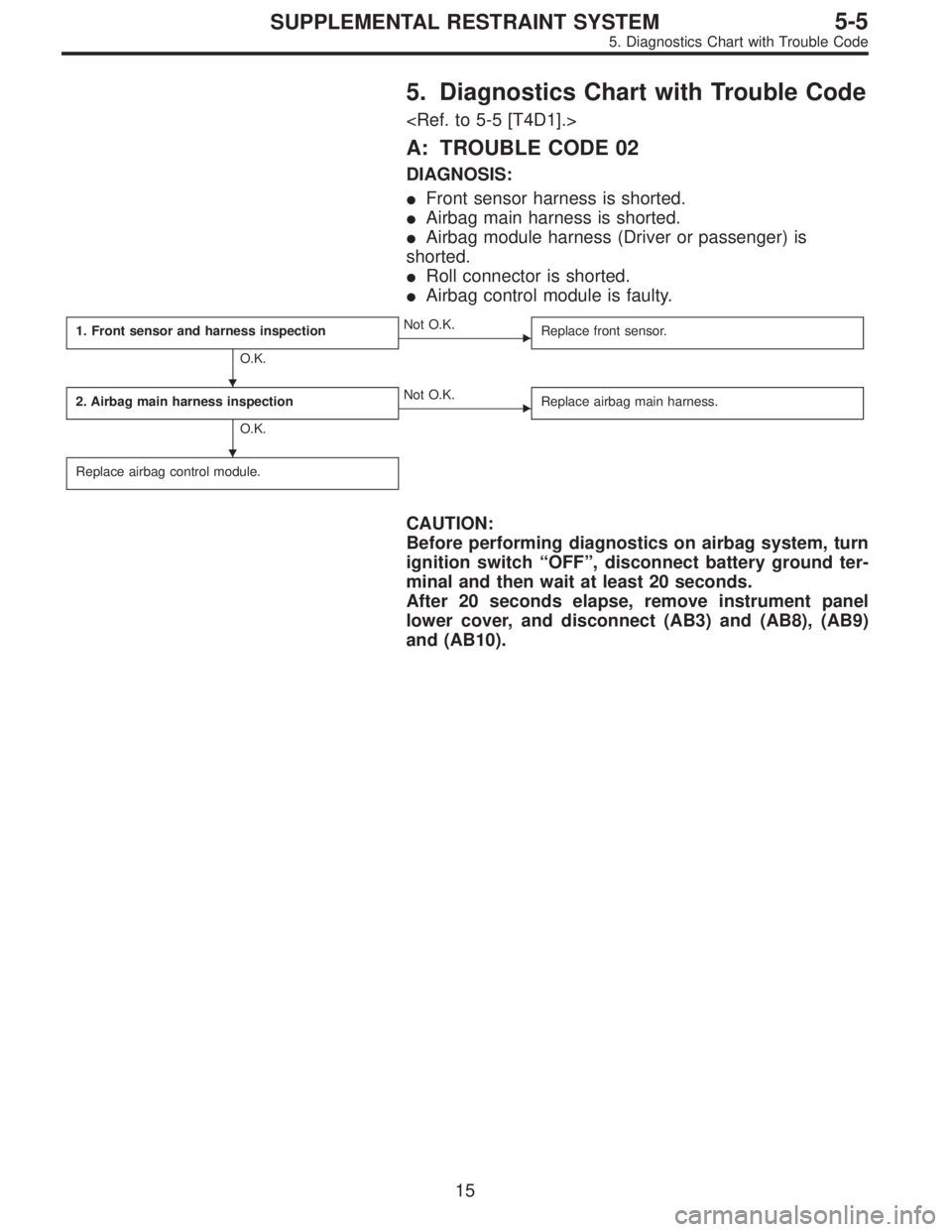
A: TROUBLE CODE 02
DIAGNOSIS:
�Front sensor harness is shorted.
�Airbag main harness is shorted.
�Airbag module harness (Driver or passenger) is
shorted.
�Roll connector is shorted.
�Airbag control module is faulty.
1. Front sensor and harness inspection
O.K.
�Not O.K.
Replace front sensor.
2. Airbag main harness inspection
O.K.
�Not O.K.
Replace airbag main harness.
Replace airbag control module.
CAUTION:
Before performing diagnostics on airbag system, turn
ignition switch“OFF”, disconnect battery ground ter-
minal and then wait at least 20 seconds.
After 20 seconds elapse, remove instrument panel
lower cover, and disconnect (AB3) and (AB8), (AB9)
and (AB10).
�
�
15
5-5SUPPLEMENTAL RESTRAINT SYSTEM
5. Diagnostics Chart with Trouble Code
Page 1825 of 2248
![SUBARU LEGACY 1995 Service Repair Manual G5M0558
1. FRONT SENSOR AND HARNESS INSPECTION
1) Disconnect connectors (AB4) and (AB5) from airbag
control module. <Ref. to 5-5 [W6A0].>
2) Connect connectors (AB4) and (AB5) to connector (8B)
of tes](/manual-img/17/57432/w960_57432-1824.png "SUBARU LEGACY 1995 Service Repair Manual G5M0558
1. FRONT SENSOR AND HARNESS INSPECTION
1) Disconnect connectors (AB4) and (AB5) from airbag
control module. <Ref. to 5-5 [W6A0].>
2) Connect connectors (AB4) and (AB5) to connector (8B)
of tes")
G5M0558
1. FRONT SENSOR AND HARNESS INSPECTION
1) Disconnect connectors (AB4) and (AB5) from airbag
control module.
2) Connect connectors (AB4) and (AB5) to connector (8B)
of test harness B2.
3) Measure resistance between connector (5B) terminal
indicated.
(5B) Terminal / Specified resistance:
(RH: AB4): No. 17 — No. 18 / 1.4 — 1.6 kΩ
(LH: AB5): No. 15 — No. 16 / 1.4 — 1.6 kΩ
4) Measure resistance between each connector (5B) ter-
minal and body.
(5B) Terminal / Specified resistance:
(RH: AB4): No. 17 — Body/1MΩ, or more
No.18—Body/1MΩ, or more
(LH: AB5): No. 15 — Body/1MΩ, or more
No.16—Body/1MΩ, or more
G5M0559
2. AIRBAG MAIN HARNESS INSPECTION
1) Disconnect connector (AB6) from airbag control module
, and connect (AB6) to test harness
B2 connector (8B).
2) Measure resistance between each (5B) terminal and
body.
(5B) Terminal / Specified resistance:
No.1—Body/1MΩ, or more
No.14—Body/1MΩ, or more
16
5-5SUPPLEMENTAL RESTRAINT SYSTEM
5. Diagnostics Chart with Trouble Code
Page 1826 of 2248
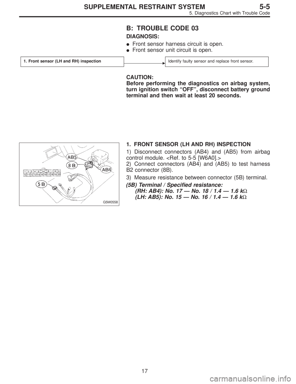
B: TROUBLE CODE 03
DIAGNOSIS:
�Front sensor harness circuit is open.
�Front sensor unit circuit is open.
1. Front sensor (LH and RH) inspection�Identify faulty sensor and replace front sensor.
CAUTION:
Before performing the diagnostics on airbag system,
turn ignition switch“OFF”, disconnect battery ground
terminal and then wait at least 20 seconds.
G5M0558
1. FRONT SENSOR (LH AND RH) INSPECTION
1) Disconnect connectors (AB4) and (AB5) from airbag
control module.
2) Connect connectors (AB4) and (AB5) to test harness
B2 connector (8B).
3) Measure resistance between connector (5B) terminal.
(5B) Terminal / Specified resistance:
(RH: AB4): No. 17—No. 18 / 1.4—1.6 kΩ
(LH: AB5): No. 15—No. 16 / 1.4—1.6 kΩ
17
5-5SUPPLEMENTAL RESTRAINT SYSTEM
5. Diagnostics Chart with Trouble Code
Page 1836 of 2248
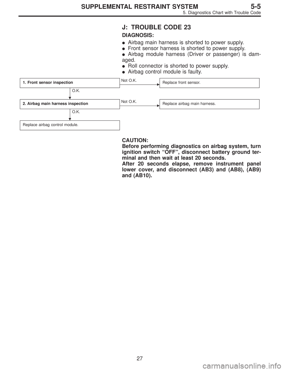
J: TROUBLE CODE 23
DIAGNOSIS:
�Airbag main harness is shorted to power supply.
�Front sensor harness is shorted to power supply.
�Airbag module harness (Driver or passenger) is dam-
aged.
�Roll connector is shorted to power supply.
�Airbag control module is faulty.
1. Front sensor inspection
O.K.
�Not O.K.
Replace front sensor.
2. Airbag main harness inspection
O.K.
�Not O.K.
Replace airbag main harness.
Replace airbag control module.
CAUTION:
Before performing diagnostics on airbag system, turn
ignition switch“OFF”, disconnect battery ground ter-
minal and then wait at least 20 seconds.
After 20 seconds elapse, remove instrument panel
lower cover, and disconnect (AB3) and (AB8), (AB9)
and (AB10).
�
�
27
5-5SUPPLEMENTAL RESTRAINT SYSTEM
5. Diagnostics Chart with Trouble Code
Page 1837 of 2248
G5M0558
1. FRONT SENSOR INSPECTION
1) Disconnect connectors (AB4) and (AB5) from airbag
control module.
2) Connect connectors (AB4) and (AB5) to test harness
B2 connector (8B).
3) Measure resistance between test harness B2 connec-
tor (5B) terminal.
(5B) Terminal / Specified resistance:
(RH: AB4): No. 17—No. 18 / 1.4—1.6 kΩ
(LH: AB5): No. 15—No. 16 / 1.4—1.6 kΩ
G5M0559
2. AIRBAG MAIN HARNESS INSPECTION
1) Disconnect connector (AB6) from airbag control module
, and connect it to test harness B2
connector (8B).
2) Connect battery ground cable and turn ignition switch
“ON”(engine off).
3) Measure voltage across each test harness B2 connec-
tor (5B) terminal and body.
(5B) Terminal / Specified voltage:
No. 1—Body/1V,orless
No. 6—Body/1V,orless
No. 7—Body/1V,orless
No. 14—Body/1V,orless
28
5-5SUPPLEMENTAL RESTRAINT SYSTEM
5. Diagnostics Chart with Trouble Code
![SUBARU LEGACY 1995 Service Repair Manual G5M0558
1. FRONT SENSOR INSPECTION
1) Disconnect connectors (AB4) and (AB5) from airbag
control module. <Ref. to 5-5 [W6A0].>
2) Connect connectors (AB4) and (AB5) to test harness
B2 connector (8B).
3](/manual-img/17/57432/w960_57432-1836.png "SUBARU LEGACY 1995 Service Repair Manual G5M0558
1. FRONT SENSOR INSPECTION
1) Disconnect connectors (AB4) and (AB5) from airbag
control module. <Ref. to 5-5 [W6A0].>
2) Connect connectors (AB4) and (AB5) to test harness
B2 connector (8B).
3")