Page 788 of 2248
 Read values indicated on the brake tester and check if
the fluctuation of values, when decompressed and
compressed, meet the standard values.
Initial value When decompressed When compressed
Front w")
7) Read values indicated on the brake tester and check if
the fluctuation of values, when decompressed and
compressed, meet the standard values.
Initial value When decompressed When compressed
Front wheel 1,961 N (200 kg, 441 lb) 245 N (25 kg, 55 lb) 1,961 N (200 kg, 441 lb)
Rear wheel 686 N (70 kg, 154 lb) 245 N (25 kg, 55 lb) 686 N (70 kg, 154 lb)
�In case of hydraulic unit plunger piston malfunction:
Initial value When decompressed When compressed
Rear right wheel 686 N (70 kg, 154 lb) 245 N (25 kg, 55 lb) 686 N (70 kg, 154 lb)
Rear left wheel 686 N (70 kg, 154 lb) 686 N (70 kg, 154 lb) 686 N (70 kg, 154 lb)
8) After checking, also check if any irregular brake pedal
tightness is felt.
9) In case of AWD vehicles, remove the spare fuse from
the FWD connector in the engine compartment to return to
the original AWD state.
C: SEQUENCE CONTROL
Under the sequence control, after the hydraulic unit sole-
noid valve is driven, the operation of the hydraulic unit can
be checked by means of the brake tester or pressure
gauge.
B4M0082A
1. OPERATIONAL GUIDELINES OF THE SEQUENCE
CONTROL
1) Connect diagnosis terminals to 3 terminals (K) and 6
terminals (L) of the diagnosis connector beside driver seat
heater unit.
2) Set the speed of all wheels at 4 km/h (2 MPH) or less.
3) Within 0.5 seconds after the ABS warning lamp goes
out, immediately after the ignition switch is turned to on,
depress the brake pedal and hold.
CAUTION:
Do not depress the clutch pedal.
NOTE:
�When the ignition switch is set to on, the brake pedal
must not be depressed.
�Engine must not operate.
71
4-4SERVICE PROCEDURE
15. Hydraulic Unit for ABS System
Page 863 of 2248
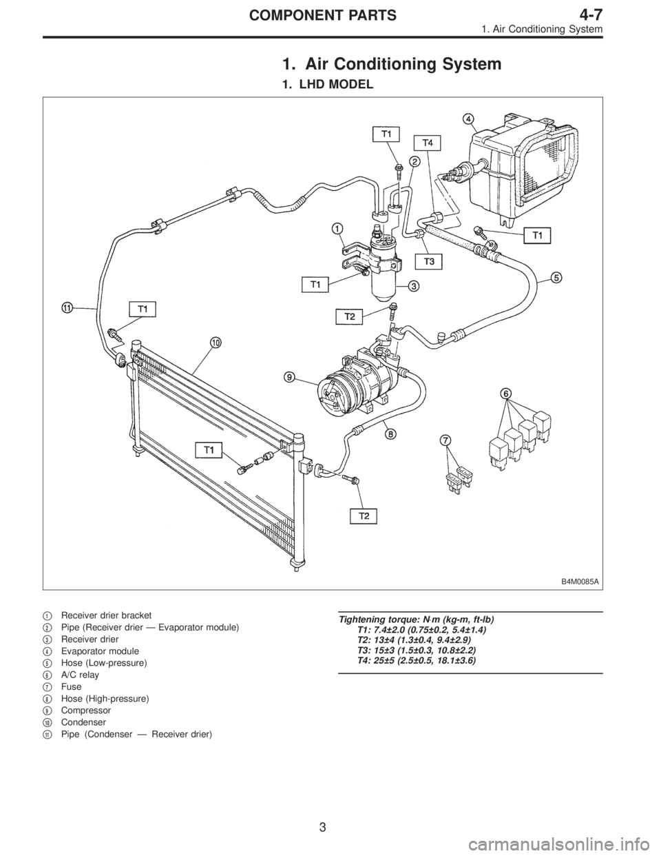
1. Air Conditioning System
1. LHD MODEL
B4M0085A
�1Receiver drier bracket
�
2Pipe (Receiver drier—Evaporator module)
�
3Receiver drier
�
4Evaporator module
�
5Hose (Low-pressure)
�
6A/C relay
�
7Fuse
�
8Hose (High-pressure)
�
9Compressor
�
10Condenser
�
11Pipe (Condenser—Receiver drier)
Tightening torque: N⋅m (kg-m, ft-lb)
T1: 7.4±2.0 (0.75±0.2, 5.4±1.4)
T2: 13±4 (1.3±0.4, 9.4±2.9)
T3: 15±3 (1.5±0.3, 10.8±2.2)
T4: 25±5 (2.5±0.5, 18.1±3.6)
3
4-7COMPONENT PARTS
1. Air Conditioning System
Page 864 of 2248
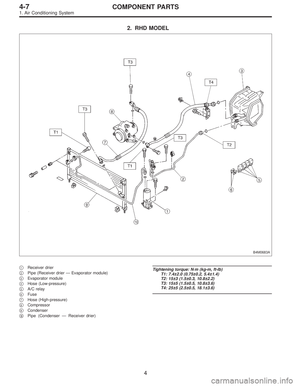
2. RHD MODEL
B4M0683A
�1Receiver drier
�
2Pipe (Receiver drier—Evaporator module)
�
3Evaporator module
�
4Hose (Low-pressure)
�
5A/C relay
�
6Fuse
�
7Hose (High-pressure)
�
8Compressor
�
9Condenser
�
10Pipe (Condenser—Receiver drier)
Tightening torque: N⋅m (kg-m, ft-lb)
T1: 7.4±2.0 (0.75±0.2, 5.4±1.4)
T2: 15±3 (1.5±0.3, 10.8±2.2)
T3: 15±5 (1.5±0.5, 10.8±3.6)
T4: 25±5 (2.5±0.5, 18.1±3.6)
4
4-7COMPONENT PARTS
1. Air Conditioning System
Page 903 of 2248
G4M0649
17. Relay and Fuse
A: LOCATION
Relays used with A/C system are located as shown in fig-
ure.
1) A/C relay
2) Main fan (radiator fan) relay
3) Sub fan (condenser fan) relay
4) Sub fan (condenser fan) water temperature relay
5) Fuses (10 A and 20 A)
G4M0651
B: INSPECTION
1) Check conduction with a circuit tester (ohm range)
according to the following table in figure.
B4M0105A
2) Replace relays which do not meet specifications.
41
4-7SERVICE PROCEDURE
17. Relay and Fuse
Page 976 of 2248

1. Sunroof
Entry of water into compartment�
1Check roof panel and glass lid assembly for improper or poor
sealing.
�
2Check drain tube for clogging.
�
3Check sunroof frame seal and body for improper fit.
Booming noise�
1Check glass lid assembly and roof panel for improper clear-
ance.
�
2Check sun shade and roof trim for improper clearance.
Abnormal motor noise�
1Check motor for looseness.
�
2Check gears and bearings for wear.
�
3Check cable for wear.
�
4Check cable pipe for deformities.
Failure of sunroof to operate
(Motor operates properly.)�
1Check guide rail for foreign particles.
�
2Check guide rail for improper installation.
�
3Check parts for mutual interference.
�
4Check cable slider for improper clinching.
�
5Check cable for improper installation.
�
6Check clutch adjustment nut for improper tightness.
Motor does not rotate or rotates improperly.
(Use sunroof wrench to check operation.)�
1Check fuse for blowout.
�
2Check switch for improper function.
�
3Check motor for incorrect terminal voltage.
�
4Check relay for improper operation.
�
5Check poor grounding system.
�
6Check cords for discontinuity and terminals for poor connec-
tions.
�
7Check limit switch for improper operation.
55
5-1DIAGNOSTICS
1. Sunroof
Page 1031 of 2248
B5M0042
6) Remove lap anchor cover and then remove lower
anchor bolt.
7) Remove outer belt assembly.
8) Installation is in the reverse order of removal. Ensure
that seat belt is properly reeled on and off after installation
of ELR.
CAUTION:
�Be extremely careful not to confuse center seat
anchor plate with outer seat anchor plate during instal-
lation.
�Ensure that seat belts are free from twisting after
installation.
�Ensure that tongues, buckles and belts are properly
placed on seat.
B5M0046A
5. Inner Trim Panel
A: REMOVAL AND INSTALLATION
1. SIDE SILL COVER
1) Remove front pillar lower trim�
1.
2) Remove side sill rear upper cover trim�
2.
B5M0047
2. CENTER PILLAR LOWER
Remove center pillar lower trim.
13
5-3SERVICE PROCEDURE
4. Rear Seat Belt - 5. Inner Trim Panel
Page 1032 of 2248
B5M0042
6) Remove lap anchor cover and then remove lower
anchor bolt.
7) Remove outer belt assembly.
8) Installation is in the reverse order of removal. Ensure
that seat belt is properly reeled on and off after installation
of ELR.
CAUTION:
�Be extremely careful not to confuse center seat
anchor plate with outer seat anchor plate during instal-
lation.
�Ensure that seat belts are free from twisting after
installation.
�Ensure that tongues, buckles and belts are properly
placed on seat.
B5M0046A
5. Inner Trim Panel
A: REMOVAL AND INSTALLATION
1. SIDE SILL COVER
1) Remove front pillar lower trim�
1.
2) Remove side sill rear upper cover trim�
2.
B5M0047
2. CENTER PILLAR LOWER
Remove center pillar lower trim.
13
5-3SERVICE PROCEDURE
4. Rear Seat Belt - 5. Inner Trim Panel
Page 1096 of 2248
, 100 minutes (AT)
Cold cranking ampere 430 amperes (MT), 490 amperes (AT)
Fuse10 A, 15 A, 20 A
Combination
meterSpeedometer")
1. Body Electrical
A: SPECIFICATIONS
BatteryReserve capacity 82 minutes (MT), 100 minutes (AT)
Cold cranking ampere 430 amperes (MT), 490 amperes (AT)
Fuse10 A, 15 A, 20 A
Combination
meterSpeedometer Electric pulse type
Tachometer Electric impulse type
Water temperature gauge Thermistor cross coil type
Fuel gauge Resistance cross coil type
Charge indicator light 12 V—1.4 W
Brake fluid level warning/parking brake indicator light 12 V—1.4 W
AT oil temperature warning light (AWD only) 12 V—1.4 W
A.B.S. warning light 12 V—1.4 W
CHECK ENGINE warning light
(Malfunction indicator lamp)12 V—1.4 W
Oil pressure warning light 12 V—1.4 W
AIRBAG system warning light 12 V—1.4 W
Low fuel warning light 12 V—3W
FWD indicator light 12 V—1.4 W
TCS warning light 12 V—1.4 W
TCS indicator light 12 V—1.4 W
Turn signal indicator light 12 V—1.4 W (2 pieces)
Seat belt warning light 12 V—1.4 W
Door open warning light 12 V—1.4 W
Headlight beam indicator light 12 V—1.4 W
Meter illumination light12 V—3 W (2 pieces)
12 V—3.4 W (4 pieces)
Headlight 12 V—60/55 W (Halogen)
Front clearance light 12 V—5W
Turn signal lightFront 12 V—21 W
Rear 12 V—21 W
Tail/Stop light 12 V—5/21 W
Back-up light 12 V—21 W
High-mount stop light12 V—18 W (SEDAN), 12 V—13 W
(WAGON)
License plate light 12 V—5W
Room light 12 V—8W
Trunk room light (SEDAN) 12 V—5W
Luggage room light (WAGON) 12 V—5W
Spot light 12 V—8 W (2 pieces)
Glove box light 12 V—3.4 W
Ash tray illumination light 12 V—1.7 W
Selector lever illumination light (AT model) 12 V—1.7 W
2
6-2SPECIFICATIONS
1. Body Electrical
 A/C relay
2) Main fan (radiator fan) relay
3) Sub fan (condenser fan) relay
4) Sub fan (condense")
 Remove lap anchor cover and then remove lower
anchor bolt.
7) Remove outer belt assembly.
8) Installation is in the reverse order of removal. Ensure
that seat belt is properly reeled on and")
 Remove lap anchor cover and then remove lower
anchor bolt.
7) Remove outer belt assembly.
8) Installation is in the reverse order of removal. Ensure
that seat belt is properly reeled on and")