Page 1441 of 2248
OBD0323
AC: DTC P0403
—EXHAUST GAS RECIRCULATION CIRCUIT
MALFUNCTION (EGRSOL)—
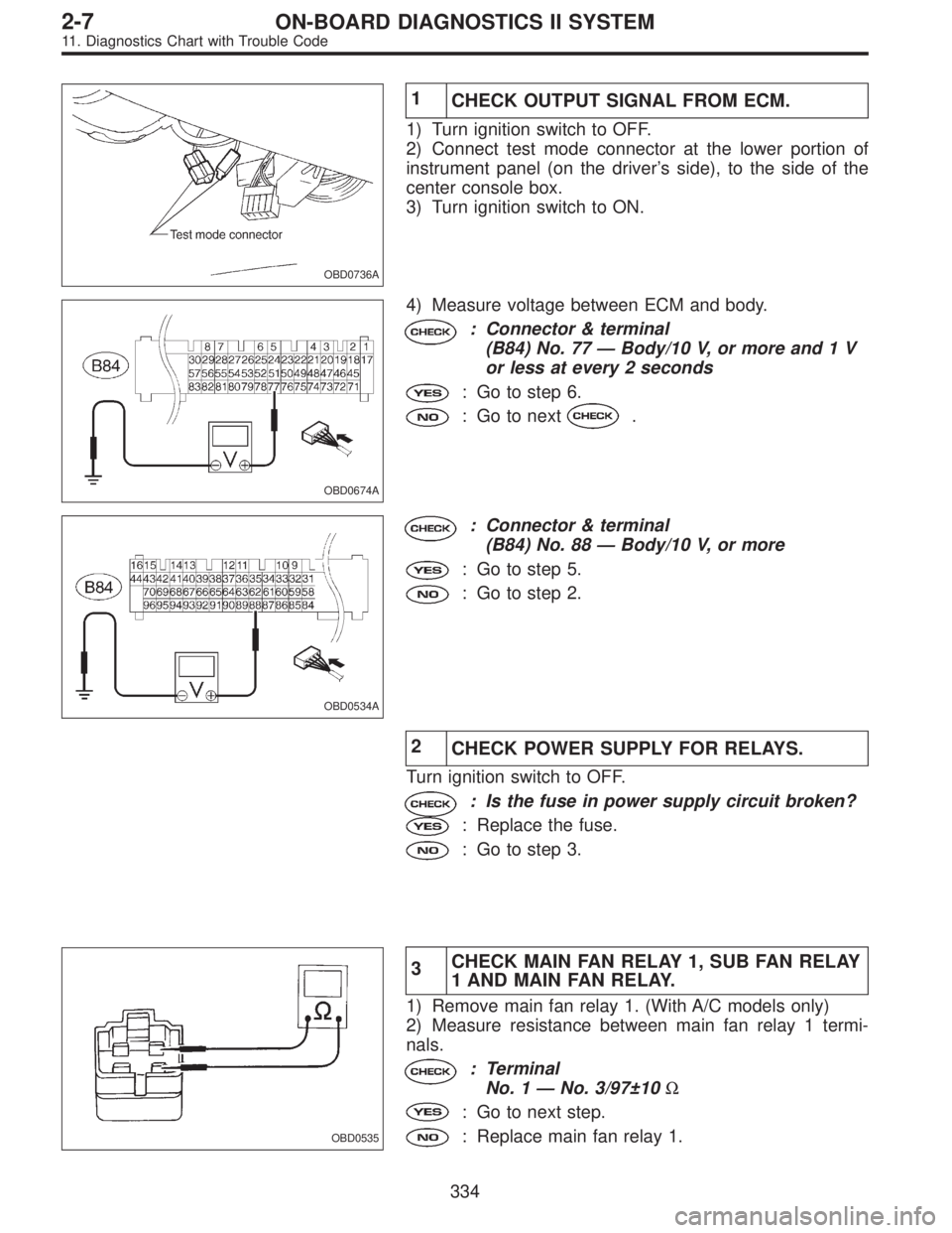
OBD0324A
DESCRIPTION:
The EGR solenoid valve is situated between the BPT and
EGR valve. EGR solenoid valve is opened by a signal
emitted from the ECM. Therefore, throttle port pressure is
transmitted to diaphragm of EGR valve.
DTC DETECTING CONDITION:
�Two consecutive trips with fault
TROUBLE SYMPTOM:
�Poor driving performance on low engine speed
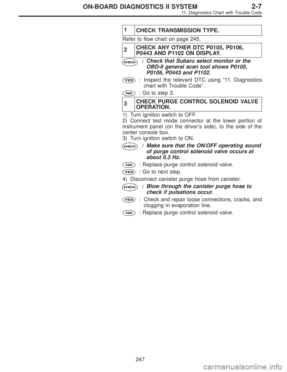
1.Check transmission type.
AT
�MT
Check AT/MT identification circuit.
2.Check output signal from ECM.
�
3.Check harness.
4.Check harness.
5.Check EGR solenoid valve.
6.Check power supply to EGR solenoid valve.
CAUTION:
After repair or replacement of faulty parts, conduct
CLEAR MEMORY and INSPECTION MODES.
[T3D0] and [T3E0].>
�
�
�
�
235
2-7ON-BOARD DIAGNOSTICS II SYSTEM
11. Diagnostics Chart with Trouble Code
Page 1453 of 2248
1
CHECK TRANSMISSION TYPE.
Refer to flow chart on page 245.
2CHECK ANY OTHER DTC P0105, P0106,
P0443 AND P1102 ON DISPLAY.
: Check that Subaru select monitor or the
OBD-II general scan tool shows P0105,
P0106, P0443 and P1102.
: Inspect the relevant DTC using“11. Diagnostics
chart with Trouble Code”.
: Go to step 3.
3CHECK PURGE CONTROL SOLENOID VALVE
OPERATION.
1) Turn ignition switch to OFF.
2) Connect test mode connector at the lower portion of
instrument panel (on the driver’s side), to the side of the
center console box.
3) Turn ignition switch to ON.
: Make sure that the ON/OFF operating sound
of purge control solenoid valve occurs at
about 0.3 Hz.
: Replace purge control solenoid valve.
: Go to next step.
4) Disconnect canister purge hose from canister.
: Blow through the canister purge hose to
check if pulsations occur.
: Check and repair loose connections, cracks, and
clogging in evaporation line.
: Replace purge control solenoid valve.
247
2-7ON-BOARD DIAGNOSTICS II SYSTEM
11. Diagnostics Chart with Trouble Code
Page 1511 of 2248
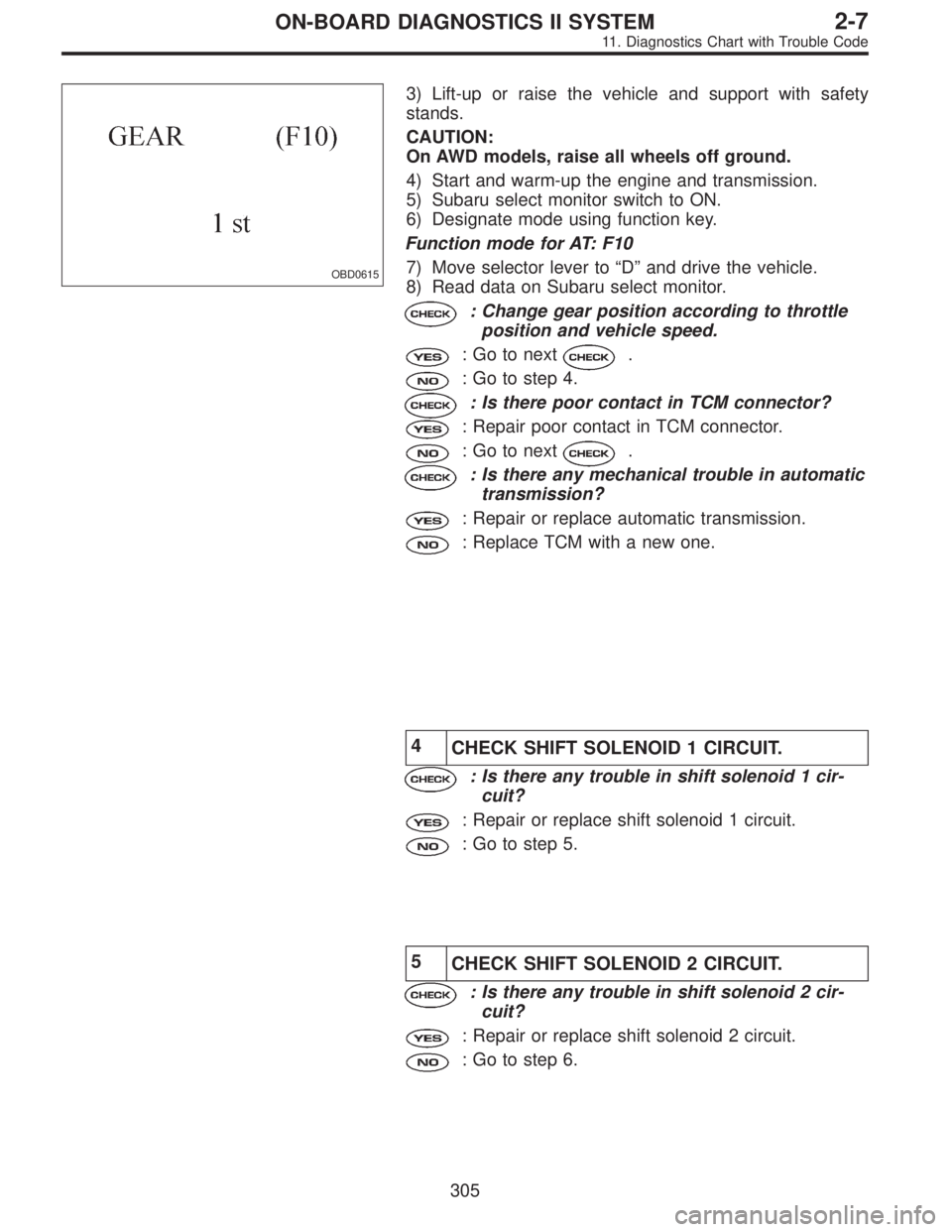
OBD0615
3) Lift-up or raise the vehicle and support with safety
stands.
CAUTION:
On AWD models, raise all wheels off ground.
4) Start and warm-up the engine and transmission.
5) Subaru select monitor switch to ON.
6) Designate mode using function key.
Function mode for AT: F10
7) Move selector lever to“D”and drive the vehicle.
8) Read data on Subaru select monitor.
: Change gear position according to throttle
position and vehicle speed.
: Go to next.
: Go to step 4.
: Is there poor contact in TCM connector?
: Repair poor contact in TCM connector.
: Go to next.
: Is there any mechanical trouble in automatic
transmission?
: Repair or replace automatic transmission.
: Replace TCM with a new one.
4
CHECK SHIFT SOLENOID 1 CIRCUIT.
: Is there any trouble in shift solenoid 1 cir-
cuit?
: Repair or replace shift solenoid 1 circuit.
: Go to step 5.
5
CHECK SHIFT SOLENOID 2 CIRCUIT.
: Is there any trouble in shift solenoid 2 cir-
cuit?
: Repair or replace shift solenoid 2 circuit.
: Go to step 6.
305
2-7ON-BOARD DIAGNOSTICS II SYSTEM
11. Diagnostics Chart with Trouble Code
Page 1540 of 2248
OBD0736A
1
CHECK OUTPUT SIGNAL FROM ECM.
1) Turn ignition switch to OFF.
2) Connect test mode connector at the lower portion of
instrument panel (on the driver’s side), to the side of the
center console box.
3) Turn ignition switch to ON.
OBD0674A
4) Measure voltage between ECM and body.
: Connector & terminal
(B84) No. 77—Body/10 V, or more and 1 V
or less at every 2 seconds
: Go to step 6.
: Go to next.
OBD0534A
: Connector & terminal
(B84) No. 88—Body/10 V, or more
: Go to step 5.
: Go to step 2.
2
CHECK POWER SUPPLY FOR RELAYS.
Turn ignition switch to OFF.
: Is the fuse in power supply circuit broken?
: Replace the fuse.
: Go to step 3.
OBD0535
3CHECK MAIN FAN RELAY 1, SUB FAN RELAY
1 AND MAIN FAN RELAY.
1) Remove main fan relay 1. (With A/C models only)
2) Measure resistance between main fan relay 1 termi-
nals.
: Terminal
No. 1—No. 3/97±10Ω
: Go to next step.
: Replace main fan relay 1.
334
2-7ON-BOARD DIAGNOSTICS II SYSTEM
11. Diagnostics Chart with Trouble Code
Page 1579 of 2248
OBD0455A
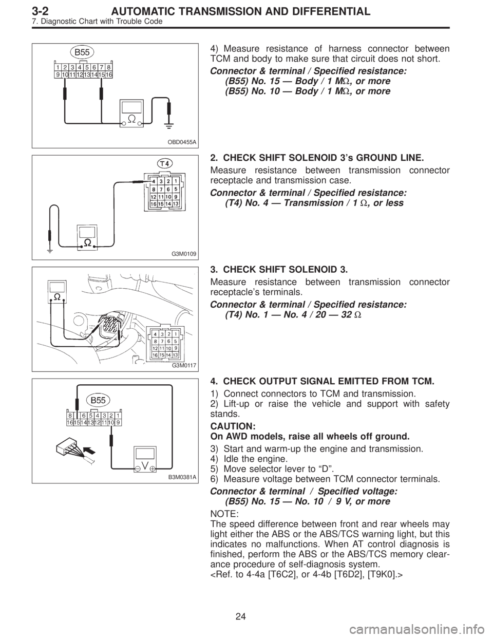
4) Measure resistance of harness connector between
TCM and body to make sure that circuit does not short.
Connector & terminal / Specified resistance:
(B55) No. 15—Body/1MΩ, or more
(B55) No. 10—Body/1MΩ, or more
G3M0109
2. CHECK SHIFT SOLENOID 3’s GROUND LINE.
Measure resistance between transmission connector
receptacle and transmission case.
Connector & terminal / Specified resistance:
(T4) No. 4—Transmission / 1Ω, or less
G3M0117
3. CHECK SHIFT SOLENOID 3.
Measure resistance between transmission connector
receptacle’s terminals.
Connector & terminal / Specified resistance:
(T4) No. 1—No.4/20—32Ω
B3M0381A
4. CHECK OUTPUT SIGNAL EMITTED FROM TCM.
1) Connect connectors to TCM and transmission.
2) Lift-up or raise the vehicle and support with safety
stands.
CAUTION:
On AWD models, raise all wheels off ground.
3) Start and warm-up the engine and transmission.
4) Idle the engine.
5) Move selector lever to“D”.
6) Measure voltage between TCM connector terminals.
Connector & terminal / Specified voltage:
(B55) No. 15—No. 10 / 9 V, or more
NOTE:
The speed difference between front and rear wheels may
light either the ABS or the ABS/TCS warning light, but this
indicates no malfunctions. When AT control diagnosis is
finished, perform the ABS or the ABS/TCS memory clear-
ance procedure of self-diagnosis system.
24
3-2AUTOMATIC TRANSMISSION AND DIFFERENTIAL
7. Diagnostic Chart with Trouble Code
Page 1581 of 2248
OBD0447A
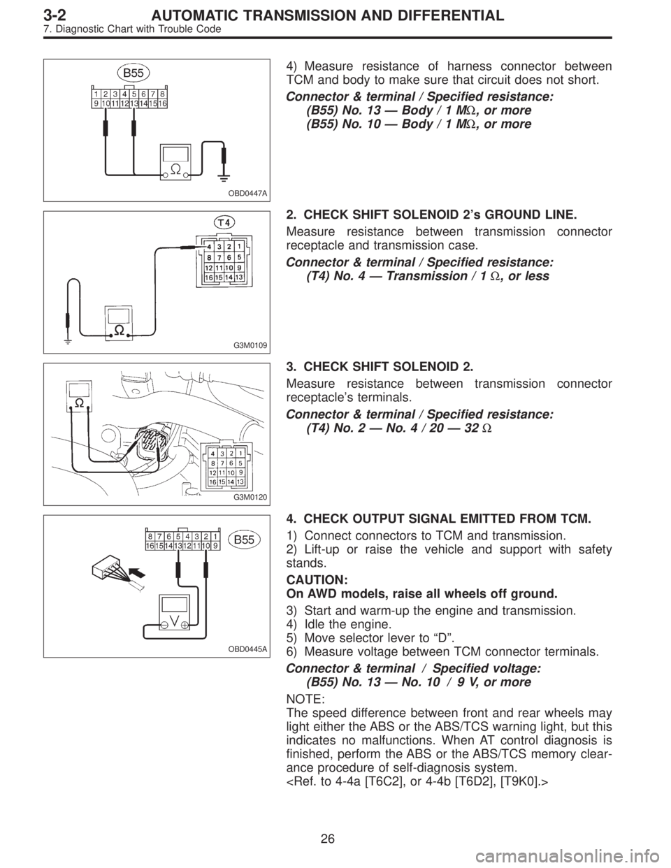
4) Measure resistance of harness connector between
TCM and body to make sure that circuit does not short.
Connector & terminal / Specified resistance:
(B55) No. 13—Body/1MΩ, or more
(B55) No. 10—Body/1MΩ, or more
G3M0109
2. CHECK SHIFT SOLENOID 2’s GROUND LINE.
Measure resistance between transmission connector
receptacle and transmission case.
Connector & terminal / Specified resistance:
(T4) No. 4—Transmission / 1Ω, or less
G3M0120
3. CHECK SHIFT SOLENOID 2.
Measure resistance between transmission connector
receptacle’s terminals.
Connector & terminal / Specified resistance:
(T4) No. 2—No.4/20—32Ω
OBD0445A
4. CHECK OUTPUT SIGNAL EMITTED FROM TCM.
1) Connect connectors to TCM and transmission.
2) Lift-up or raise the vehicle and support with safety
stands.
CAUTION:
On AWD models, raise all wheels off ground.
3) Start and warm-up the engine and transmission.
4) Idle the engine.
5) Move selector lever to“D”.
6) Measure voltage between TCM connector terminals.
Connector & terminal / Specified voltage:
(B55) No. 13—No. 10 / 9 V, or more
NOTE:
The speed difference between front and rear wheels may
light either the ABS or the ABS/TCS warning light, but this
indicates no malfunctions. When AT control diagnosis is
finished, perform the ABS or the ABS/TCS memory clear-
ance procedure of self-diagnosis system.
26
3-2AUTOMATIC TRANSMISSION AND DIFFERENTIAL
7. Diagnostic Chart with Trouble Code
Page 1583 of 2248
OBD0439A
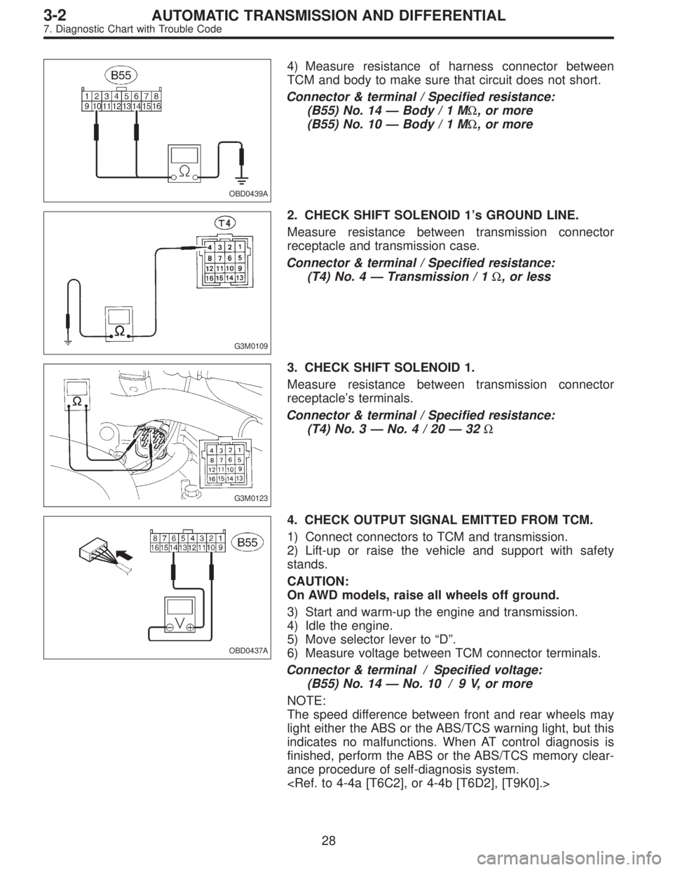
4) Measure resistance of harness connector between
TCM and body to make sure that circuit does not short.
Connector & terminal / Specified resistance:
(B55) No. 14—Body/1MΩ, or more
(B55) No. 10—Body/1MΩ, or more
G3M0109
2. CHECK SHIFT SOLENOID 1’s GROUND LINE.
Measure resistance between transmission connector
receptacle and transmission case.
Connector & terminal / Specified resistance:
(T4) No. 4—Transmission / 1Ω, or less
G3M0123
3. CHECK SHIFT SOLENOID 1.
Measure resistance between transmission connector
receptacle’s terminals.
Connector & terminal / Specified resistance:
(T4) No. 3—No.4/20—32Ω
OBD0437A
4. CHECK OUTPUT SIGNAL EMITTED FROM TCM.
1) Connect connectors to TCM and transmission.
2) Lift-up or raise the vehicle and support with safety
stands.
CAUTION:
On AWD models, raise all wheels off ground.
3) Start and warm-up the engine and transmission.
4) Idle the engine.
5) Move selector lever to“D”.
6) Measure voltage between TCM connector terminals.
Connector & terminal / Specified voltage:
(B55) No. 14—No. 10 / 9 V, or more
NOTE:
The speed difference between front and rear wheels may
light either the ABS or the ABS/TCS warning light, but this
indicates no malfunctions. When AT control diagnosis is
finished, perform the ABS or the ABS/TCS memory clear-
ance procedure of self-diagnosis system.
28
3-2AUTOMATIC TRANSMISSION AND DIFFERENTIAL
7. Diagnostic Chart with Trouble Code
Page:
< prev 1-8 9-16 17-24