Page 721 of 2248
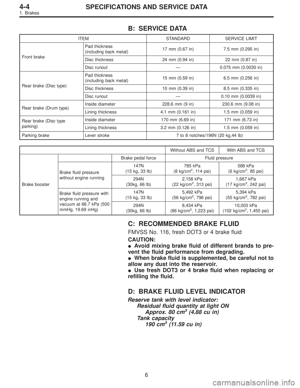
B: SERVICE DATA
ITEM STANDARD SERVICE LIMIT
Front brakePad thickness
(including back metal)17 mm (0.67 in) 7.5 mm (0.295 in)
Disc thickness 24 mm (0.94 in) 22 mm (0.87 in)
Disc runout—0.075 mm (0.0030 in)
Rear brake (Disc type)Pad thickness
(including back metal)15 mm (0.59 in) 6.5 mm (0.256 in)
Disc thickness 10 mm (0.39 in) 8.5 mm (0.335 in)
Disc runout—0.10 mm (0.0039 in)
Rear brake (Drum type)Inside diameter 228.6 mm (9 in) 230.6 mm (9.08 in)
Lining thickness 4.1 mm (0.161 in) 1.5 mm (0.059 in)
Rear brake (Disc type
parking)Inside diameter 170 mm (6.69 in) 171 mm (6.73 in)
Lining thickness 3.2 mm (0.126 in) 1.5 mm (0.059 in)
Parking brake Lever stroke 7 to 8 notches/196N (20 kg,44 lb)
Without ABS and TCS With ABS and TCS
Brake boosterBrake pedal force Fluid pressure
Brake fluid pressure
without engine running147N
(15 kg, 33 lb)785 kPa
(8 kg/cm
2, 114 psi)588 kPa
(6 kg/cm2, 85 psi)
294N
(30kg, 66 lb)2,158 kPa
(22 kg/cm
2, 313 psi)1,667 kPa
(17 kg/cm2, 242 psi)
Brake fluid pressure with
engine running and
vacuum at 66.7 kPa (500
mmHg, 19.69 inHg)147N
(15 kg, 33 lb)5,492 kPa
(56 kg/cm
2, 796 psi)5,394 kPa
(55 kg/cm2, 782 psi)
294N
(30kg, 66 lb)8,434 kPa
(86 kg/cm
2, 1,223 psi)10,003 kPa
(102 kg/cm2, 1,450 psi)
C: RECOMMENDED BRAKE FLUID
FMVSS No. 116, fresh DOT3 or 4 brake fluid
CAUTION:
�Avoid mixing brake fluid of different brands to pre-
vent the fluid performance from degrading.
�When brake fluid is supplemented, be careful not to
allow any dust into the reservoir.
�Use fresh DOT3 or 4 brake fluid when replacing or
refilling the fluid.
D: BRAKE FLUID LEVEL INDICATOR
Reserve tank with level indicator:
Residual fluid quantity at light ON
Approx. 80 cm
3(4.88 cu in)
Tank capacity
190 cm
3(11.59 cu in)
6
4-4SPECIFICATIONS AND SERVICE DATA
1. Brakes
Page 735 of 2248
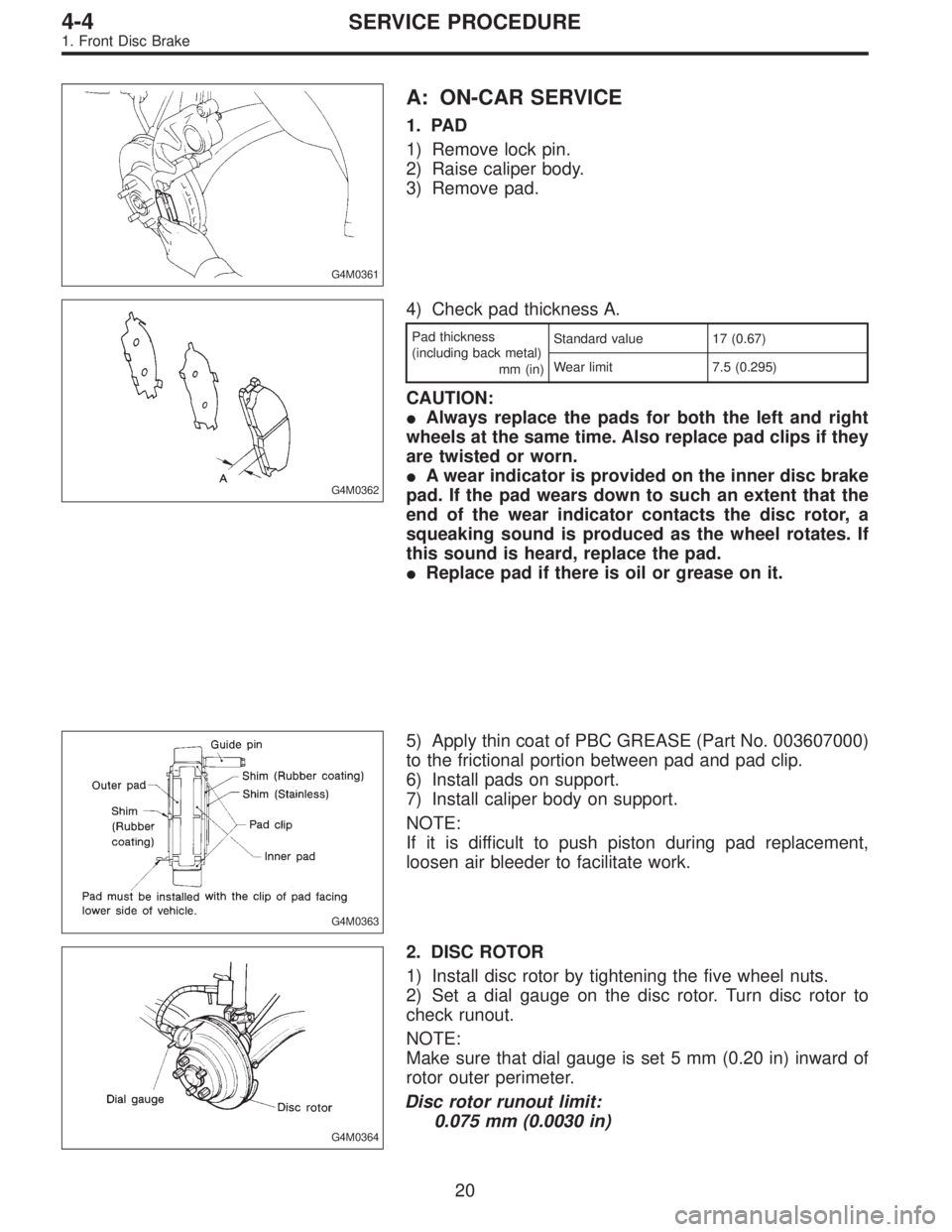
G4M0361
A: ON-CAR SERVICE
1. PAD
1) Remove lock pin.
2) Raise caliper body.
3) Remove pad.
G4M0362
4) Check pad thickness A.
Pad thickness
(including back metal)
mm (in)Standard value 17 (0.67)
Wear limit 7.5 (0.295)
CAUTION:
�Always replace the pads for both the left and right
wheels at the same time. Also replace pad clips if they
are twisted or worn.
�A wear indicator is provided on the inner disc brake
pad. If the pad wears down to such an extent that the
end of the wear indicator contacts the disc rotor, a
squeaking sound is produced as the wheel rotates. If
this sound is heard, replace the pad.
�Replace pad if there is oil or grease on it.
G4M0363
5) Apply thin coat of PBC GREASE (Part No. 003607000)
to the frictional portion between pad and pad clip.
6) Install pads on support.
7) Install caliper body on support.
NOTE:
If it is difficult to push piston during pad replacement,
loosen air bleeder to facilitate work.
G4M0364
2. DISC ROTOR
1) Install disc rotor by tightening the five wheel nuts.
2) Set a dial gauge on the disc rotor. Turn disc rotor to
check runout.
NOTE:
Make sure that dial gauge is set 5 mm (0.20 in) inward of
rotor outer perimeter.
Disc rotor runout limit:
0.075 mm (0.0030 in)
20
4-4SERVICE PROCEDURE
1. Front Disc Brake
Page 739 of 2248
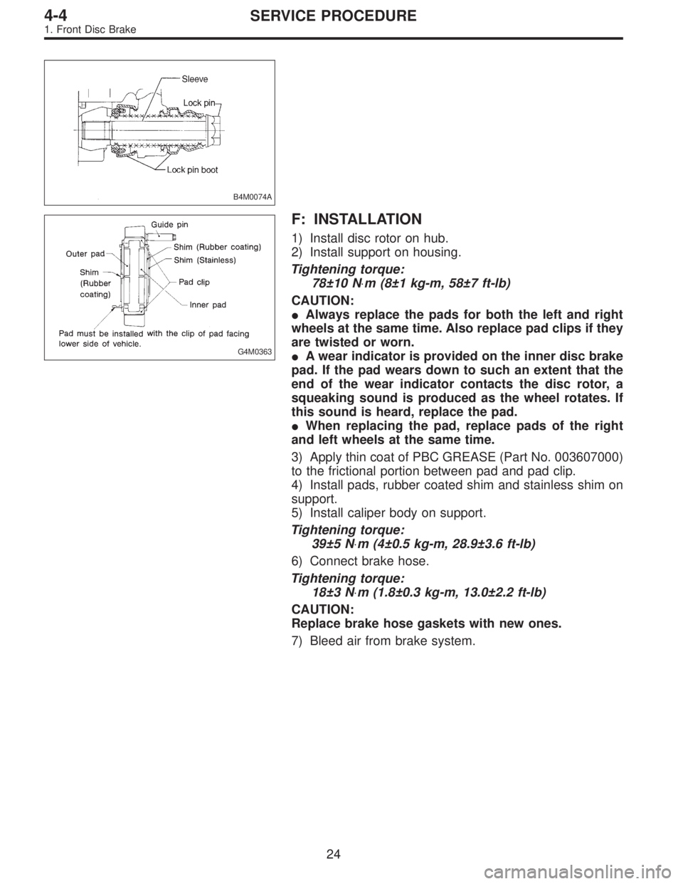
B4M0074A
G4M0363
F: INSTALLATION
1) Install disc rotor on hub.
2) Install support on housing.
Tightening torque:
78±10 N⋅m (8±1 kg-m, 58±7 ft-lb)
CAUTION:
�Always replace the pads for both the left and right
wheels at the same time. Also replace pad clips if they
are twisted or worn.
�A wear indicator is provided on the inner disc brake
pad. If the pad wears down to such an extent that the
end of the wear indicator contacts the disc rotor, a
squeaking sound is produced as the wheel rotates. If
this sound is heard, replace the pad.
�When replacing the pad, replace pads of the right
and left wheels at the same time.
3) Apply thin coat of PBC GREASE (Part No. 003607000)
to the frictional portion between pad and pad clip.
4) Install pads, rubber coated shim and stainless shim on
support.
5) Install caliper body on support.
Tightening torque:
39±5 N⋅m (4±0.5 kg-m, 28.9±3.6 ft-lb)
6) Connect brake hose.
Tightening torque:
18±3 N⋅m (1.8±0.3 kg-m, 13.0±2.2 ft-lb)
CAUTION:
Replace brake hose gaskets with new ones.
7) Bleed air from brake system.
24
4-4SERVICE PROCEDURE
1. Front Disc Brake
Page 741 of 2248
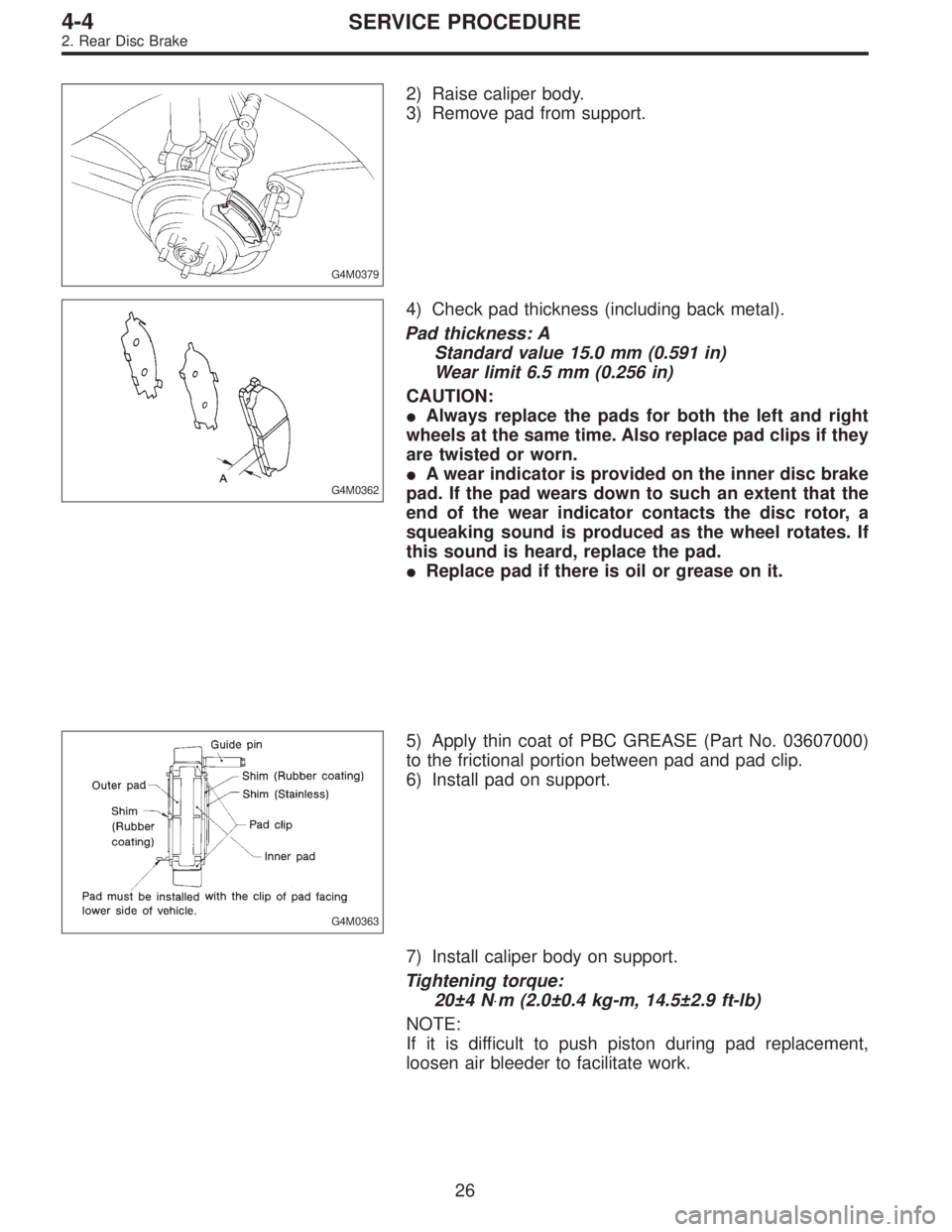
G4M0379
2) Raise caliper body.
3) Remove pad from support.
G4M0362
4) Check pad thickness (including back metal).
Pad thickness: A
Standard value 15.0 mm (0.591 in)
Wear limit 6.5 mm (0.256 in)
CAUTION:
�Always replace the pads for both the left and right
wheels at the same time. Also replace pad clips if they
are twisted or worn.
�A wear indicator is provided on the inner disc brake
pad. If the pad wears down to such an extent that the
end of the wear indicator contacts the disc rotor, a
squeaking sound is produced as the wheel rotates. If
this sound is heard, replace the pad.
�Replace pad if there is oil or grease on it.
G4M0363
5) Apply thin coat of PBC GREASE (Part No. 03607000)
to the frictional portion between pad and pad clip.
6) Install pad on support.
7) Install caliper body on support.
Tightening torque:
20±4 N⋅m (2.0±0.4 kg-m, 14.5±2.9 ft-lb)
NOTE:
If it is difficult to push piston during pad replacement,
loosen air bleeder to facilitate work.
26
4-4SERVICE PROCEDURE
2. Rear Disc Brake
Page 745 of 2248
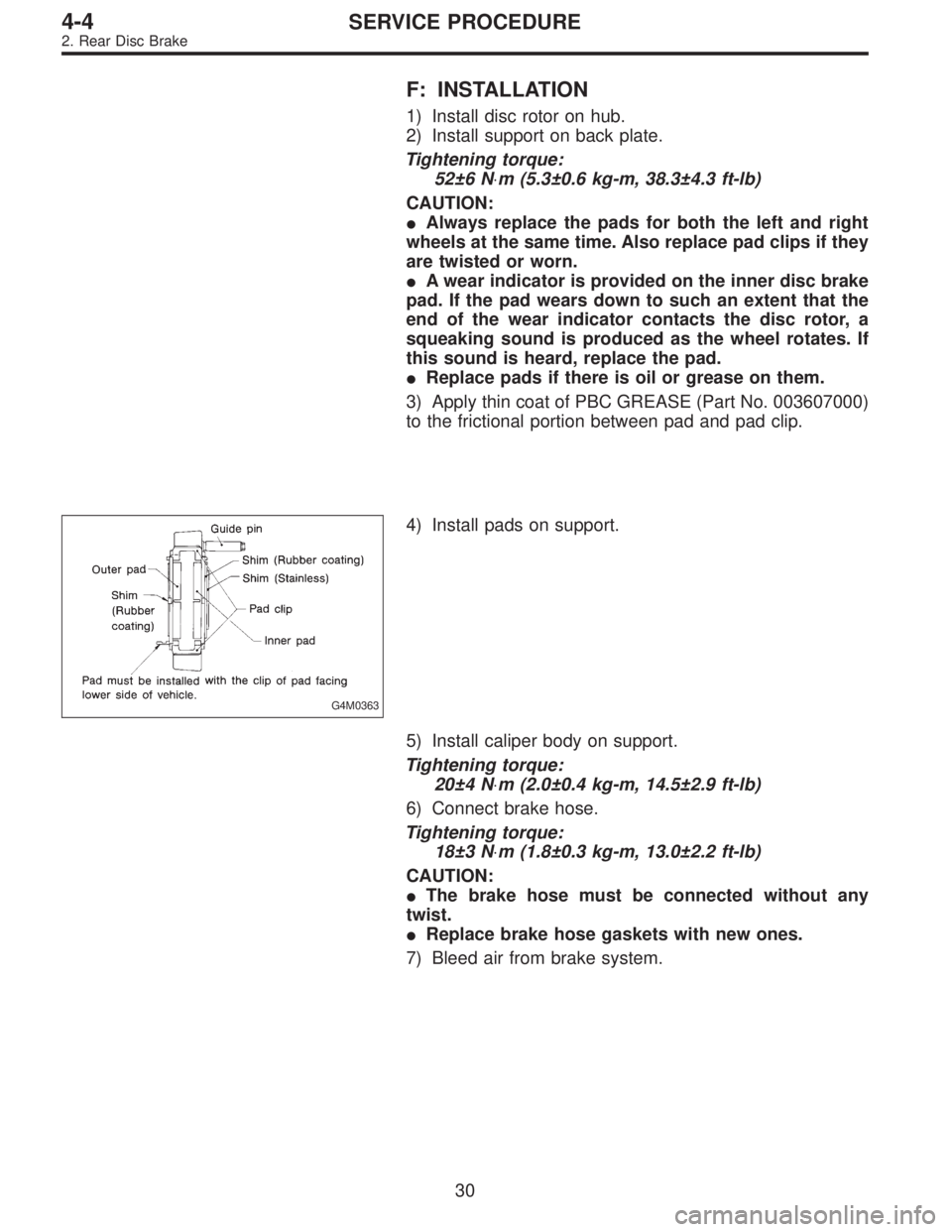
F: INSTALLATION
1) Install disc rotor on hub.
2) Install support on back plate.
Tightening torque:
52±6 N⋅m (5.3±0.6 kg-m, 38.3±4.3 ft-lb)
CAUTION:
�Always replace the pads for both the left and right
wheels at the same time. Also replace pad clips if they
are twisted or worn.
�A wear indicator is provided on the inner disc brake
pad. If the pad wears down to such an extent that the
end of the wear indicator contacts the disc rotor, a
squeaking sound is produced as the wheel rotates. If
this sound is heard, replace the pad.
�Replace pads if there is oil or grease on them.
3) Apply thin coat of PBC GREASE (Part No. 003607000)
to the frictional portion between pad and pad clip.
G4M0363
4) Install pads on support.
5) Install caliper body on support.
Tightening torque:
20±4 N⋅m (2.0±0.4 kg-m, 14.5±2.9 ft-lb)
6) Connect brake hose.
Tightening torque:
18±3 N⋅m (1.8±0.3 kg-m, 13.0±2.2 ft-lb)
CAUTION:
�The brake hose must be connected without any
twist.
�Replace brake hose gaskets with new ones.
7) Bleed air from brake system.
30
4-4SERVICE PROCEDURE
2. Rear Disc Brake
Page 755 of 2248
G4M0416
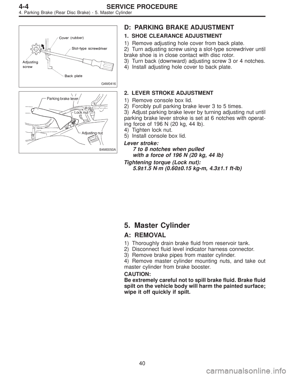
D: PARKING BRAKE ADJUSTMENT
1. SHOE CLEARANCE ADJUSTMENT
1) Remove adjusting hole cover from back plate.
2) Turn adjusting screw using a slot-type screwdriver until
brake shoe is in close contact with disc rotor.
3) Turn back (downward) adjusting screw 3 or 4 notches.
4) Install adjusting hole cover to back plate.
B4M0050A
2. LEVER STROKE ADJUSTMENT
1) Remove console box lid.
2) Forcibly pull parking brake lever 3 to 5 times.
3) Adjust parking brake lever by turning adjusting nut until
parking brake lever stroke is set at 6 notches with operat-
ing force of 196 N (20 kg, 44 lb).
4) Tighten lock nut.
5) Install console box lid.
Lever stroke:
7 to 8 notches when pulled
with a force of 196 N (20 kg, 44 lb)
Tightening torque (Lock nut):
5.9±1.5 N⋅m (0.60±0.15 kg-m, 4.3±1.1 ft-lb)
5. Master Cylinder
A: REMOVAL
1) Thoroughly drain brake fluid from reservoir tank.
2) Disconnect fluid level indicator harness connector.
3) Remove brake pipes from master cylinder.
4) Remove master cylinder mounting nuts, and take out
master cylinder from brake booster.
CAUTION:
Be extremely careful not to spill brake fluid. Brake fluid
spilt on the vehicle body will harm the painted surface;
wipe it off quickly if spilt.
40
4-4SERVICE PROCEDURE
4. Parking Brake (Rear Disc Brake) - 5. Master Cylinder
Page 756 of 2248
G4M0416
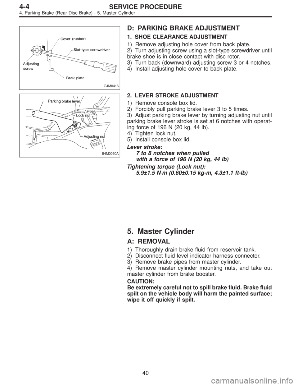
D: PARKING BRAKE ADJUSTMENT
1. SHOE CLEARANCE ADJUSTMENT
1) Remove adjusting hole cover from back plate.
2) Turn adjusting screw using a slot-type screwdriver until
brake shoe is in close contact with disc rotor.
3) Turn back (downward) adjusting screw 3 or 4 notches.
4) Install adjusting hole cover to back plate.
B4M0050A
2. LEVER STROKE ADJUSTMENT
1) Remove console box lid.
2) Forcibly pull parking brake lever 3 to 5 times.
3) Adjust parking brake lever by turning adjusting nut until
parking brake lever stroke is set at 6 notches with operat-
ing force of 196 N (20 kg, 44 lb).
4) Tighten lock nut.
5) Install console box lid.
Lever stroke:
7 to 8 notches when pulled
with a force of 196 N (20 kg, 44 lb)
Tightening torque (Lock nut):
5.9±1.5 N⋅m (0.60±0.15 kg-m, 4.3±1.1 ft-lb)
5. Master Cylinder
A: REMOVAL
1) Thoroughly drain brake fluid from reservoir tank.
2) Disconnect fluid level indicator harness connector.
3) Remove brake pipes from master cylinder.
4) Remove master cylinder mounting nuts, and take out
master cylinder from brake booster.
CAUTION:
Be extremely careful not to spill brake fluid. Brake fluid
spilt on the vehicle body will harm the painted surface;
wipe it off quickly if spilt.
40
4-4SERVICE PROCEDURE
4. Parking Brake (Rear Disc Brake) - 5. Master Cylinder
Page 759 of 2248
6. Brake Booster
A: REMOVAL
1) Remove or disconnect the following parts at engine
compartment.
(1) Disconnect connector for brake fluid level indicator.
(2) Remove brake pipes from master cylinder.
(3) Remove master cylinder installing nuts.
(4) Disconnect vacuum hose from brake booster.
2) Remove the following parts from the pedal bracket.
(1) Snap pin and clevis pin
(2) Four brake booster installing nuts
3) Remove brake booster while shunning brake pipes.
B4M0117A
B: INSTALLATION
1) Mount brake booster in position.
2) Connect operating rod to brake pedal with clevis pin
and snap pin.
�
1Clevis pin
�
2Snap pin
�
3Operating rod
G4M0420
3) Connect vacuum hose to brake booster.
4) Mount master cylinder onto brake booster.
5) Connect brake pipes to master cylinder.
6) Connect electric connector for brake fluid level indica-
tor.
43
4-4SERVICE PROCEDURE
6. Brake Booster