Page 315 of 2248
G3M0552
9) Position balls�17, checking ball springs�18and gaskets
�
19into 3-4 and 1-2 rod holes, and install plugs�20.
CAUTION:
Replace gasket with a new one.
G3M0547
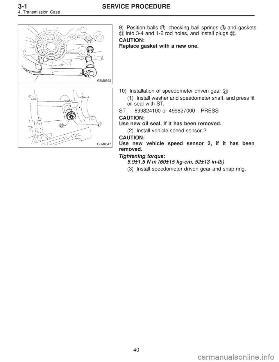
10) Installation of speedometer driven gear�21
(1) Install washer and speedometer shaft, and press fit
oil seal with ST.
ST 899824100 or 499827000 PRESS
CAUTION:
Use new oil seal, if it has been removed.
(2) Install vehicle speed sensor 2.
CAUTION:
Use new vehicle speed sensor 2, if it has been
removed.
Tightening torque:
5.9±1.5 N⋅m (60±15 kg-cm, 52±13 in-lb)
(3) Install speedometer driven gear and snap ring.
40
3-1SERVICE PROCEDURE
4. Transmission Case
Page 316 of 2248
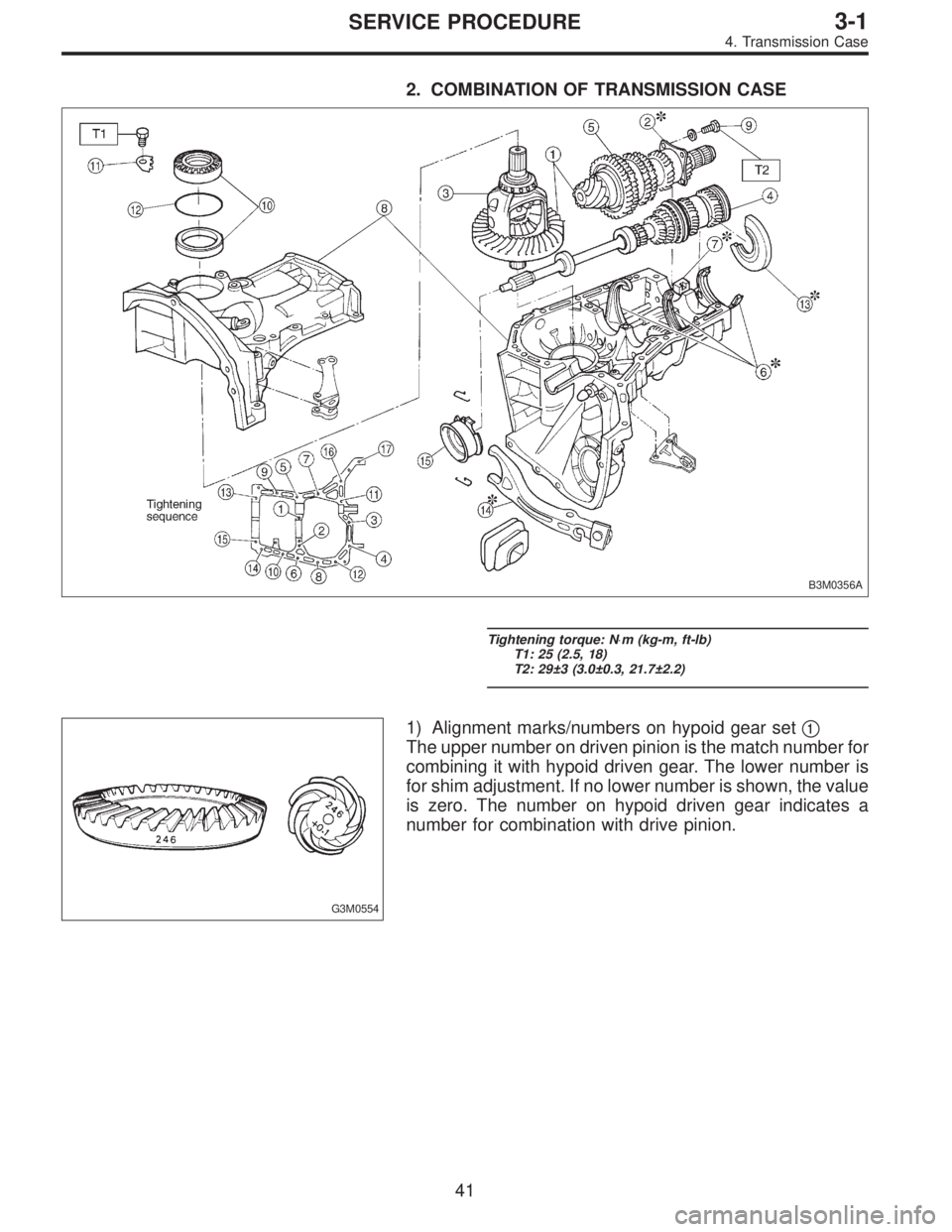
2. COMBINATION OF TRANSMISSION CASE
B3M0356A
Tightening torque: N⋅m (kg-m, ft-lb)
T1: 25 (2.5, 18)
T2: 29±3 (3.0±0.3, 21.7±2.2)
G3M0554
1) Alignment marks/numbers on hypoid gear set�1
The upper number on driven pinion is the match number for
combining it with hypoid driven gear. The lower number is
for shim adjustment. If no lower number is shown, the value
is zero. The number on hypoid driven gear indicates a
number for combination with drive pinion.
41
3-1SERVICE PROCEDURE
4. Transmission Case
Page 320 of 2248
 Combination of transmission case
(1) Wipe off grease, oil and dust on the mating sur-
faces of transmission cases with white gasoline, and
apply liquid gasket, and then put case ri")
B3M0399A
B3M0331
8) Combination of transmission case
(1) Wipe off grease, oil and dust on the mating sur-
faces of transmission cases with white gasoline, and
apply liquid gasket, and then put case right side and left
side together.
Liquid gasket:
THREE BOND 1215 or equivalent
(2) Tighten 17 bolts with bracket, clip, etc. as shown in
the figure.
Tightening torque:
8 mm bolt
25±2 N⋅m (2.5±0.2 kg-m, 18.1±1.4 ft-lb)
�10 mm bolt
39±3 N⋅m (4.0±0.3 kg-m, 28.9±2.2 ft-lb)
NOTE:
�Insert bolts from the bottom and tighten nuts at the top.
�Put cases together so that drive pinion shim and input
shaft holder shim are not caught up in between.
�Confirm that counter gear and speedometer gear are
meshed.
G3M0597
9) Tighten ball bearing attachment bolts.
Tightening torque:
29±3 N⋅m (3.0±0.3 kg-m, 21.7±2.2 ft-lb)
G3M0563
10) Backlash adjustment of hypoid gear and preload
adjustment of roller bearing
NOTE:
Support drive pinion assembly with ST.
ST 498427100 STOPPER
45
3-1SERVICE PROCEDURE
4. Transmission Case
Page 323 of 2248
B3M0073
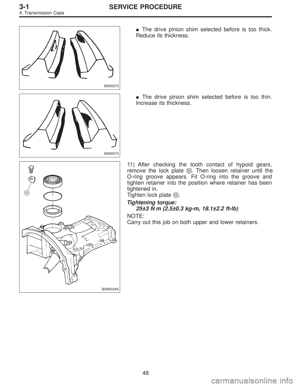
�The drive pinion shim selected before is too thick.
Reduce its thickness.
B3M0074
�The drive pinion shim selected before is too thin.
Increase its thickness.
B3M0334A
11) After checking the tooth contact of hypoid gears,
remove the lock plate�
11. Then loosen retainer until the
O-ring groove appears. Fit O-ring into the groove and
tighten retainer into the position where retainer has been
tightened in.
Tighten lock plate�
11.
Tightening torque:
25±3 N⋅m (2.5±0.3 kg-m, 18.1±2.2 ft-lb)
NOTE:
Carry out this job on both upper and lower retainers.
48
3-1SERVICE PROCEDURE
4. Transmission Case
Page 328 of 2248
G3M0618
6) Install lock washer (42 x 53 x 2). Install lock nut (42 x
13) and tighten to the specified torque using ST.
ST 499987300 SOCKET WRENCH (50)
Tightening torque:
245±10 N⋅m (25±1 kg-m, 181±7 ft-lb)
B3M0079A
NOTE:
�Stake lock nut at two points.
�Using spring balancer, check that starting torque of roller
bearing�
2is 0.1 to 1.5 N⋅m (1 to 15 kg-cm, 0.9 to 13.0 in-
lb).
B3M0080A
3. DRIVE PINION SHAFT
1) Install roller bearing onto drive pinion. Install washer�
1
(33 x 50 x 5) using ST1, ST2 and press.
ST1 499277100 BUSH 1-2 INSTALLER
ST2 499277200 INSTALLER
B3M0081A
NOTE:
When installing roller bearing�
2, note its directions (front
and rear) because knock pin hole�
3in outer race is offset.
B3M0082A
2) Install thrust bearing (33 x 50 x 3) and needle bearing
(30 x 37 x 23). Install driven shaft assembly�
4.
53
3-1SERVICE PROCEDURE
5. Drive Pinion Assembly (AWD Model)
Page 329 of 2248
 Install drive pinion collar�5, needle bearing�6(25x30
x 20), adjusting washer No. 2�
7(25 x 36 x 4), thrust bear-
ing�
8(25 x 37.5 x 3), adjusting washer No. 1�9(25x36
x t) and differentia")
B3M0083A
3) Install drive pinion collar�5, needle bearing�6(25x30
x 20), adjusting washer No. 2�
7(25 x 36 x 4), thrust bear-
ing�
8(25 x 37.5 x 3), adjusting washer No. 1�9(25x36
x t) and differential bevel gear sleeve�
10in that order.
NOTE:
Be careful because spacer must be installed in proper
direction.
�
A: Driven shaft
�
B: Driven pinion shaft
B3M0084A
G3M0625
4. ADJUSTMENT OF THRUST BEARING PRELOAD
1) After completing the preceding steps 1) through 3),
select adjusting washer No. 2 so that dimension�
His zero
through visual check. Position washer (18.3 x 30 x 4) and
lock washer (18 x 30 x 2) and install lock nut (18 x 13.5).
G3M0626
2) Using ST1, ST2 and ST3, tighten lock nut to the speci-
fied torque.
ST1 899884100 HOLDER
ST2 498427100 STOPPER
ST3 899988608 SOCKET WRENCH (27)
Tightening torque:
118±8 N⋅m (12±0.8 kg-m, 86.8±5.8 ft-lb)
B3M0085A
3) After removing ST2, measure starting torque using
torque driver.
ST1 899884100 HOLDER
ST3 899988608 SOCKET WRENCH (27)
Starting torque:
54±25 N⋅m (5.5±2.5 kg-m, 40±18 ft-lb)
54
3-1SERVICE PROCEDURE
5. Drive Pinion Assembly (AWD Model)
Page 330 of 2248
 If starting torque is not within specified limit, select new
adjusting washer No. 1�
2and recheck starting torque.
Adjusting washer No. 1
Part No. Thickness mm (in)
803025051 3.925 (0.1545)")
G3M0606
4) If starting torque is not within specified limit, select new
adjusting washer No. 1�
2and recheck starting torque.
Adjusting washer No. 1
Part No. Thickness mm (in)
803025051 3.925 (0.1545)
803025052 3.950 (0.1555)
803025053 3.975 (0.1565)
803025054 4.000 (0.1575)
803025055 4.025 (0.1585)
803025056 4.050 (0.1594)
803025057 4.075 (0.1604)
G3M0606
5) If specified starting torque range cannot be obtained
when a No. 1�
2adjusting washer is used, then select a
suitable No. 2�
3adjusting washer from those listed in the
following table. Repeat steps 1) through 4) to adjust start-
ing torque.
Starting torque Dimension H Washer No. 2
Low Small Select thicker one.
High Large Select thinner one.
Adjusting washer No. 2
Part No. Thickness mm (in)
803025059 3.850 (0.1516)
803025054 4.000 (0.1575)
803025058 4.150 (0.1634)
6) Recheck that starting torque is within specified range,
then clinch lock nut at four positions.
55
3-1SERVICE PROCEDURE
5. Drive Pinion Assembly (AWD Model)
Page 334 of 2248
G3M0640
10) Install ball bearing (29 x 74 x 38) on drive pinion shaft
with ST.
ST 499277100 INSTALLER
G3M0617
11) Position woodruff key in groove on the rear of drive
pinion shaft. Install 5th driven gear onto drive shaft using
ST and press.
ST 499277100 INSTALLER
CAUTION:
�Face 5th driven gear in the correct direction.
�Be careful not to dislocate woodruff key while
installing 5th gear.
B3M0353A
G3M0628
12) Install lock washer and tighten lock nut to the specified
torque using ST1 and ST2.
ST1 499987100 or 499987003 or 899984103 SOCKET
WRENCH (35)
ST2 899884100 HOLDER
CAUTION:
�Discard old lock nuts, replace with new ones.
�Secure lock nut in four places.
Tightening torque:
11 2—124 N⋅m (11.4—12.6 kg-m, 82—91 ft-lb)
59
3-1SERVICE PROCEDURE
6. Drive Pinion Assembly (FWD Model)
 Install lock washer (42 x 53 x 2). Install lock nut (42 x
13) and tighten to the specified torque using ST.
ST 499987300 SOCKET WRENCH (50)
Tightening torque:
245±10 N⋅m (25±1 kg-m, 181")
 Install ball bearing (29 x 74 x 38) on drive pinion shaft
with ST.
ST 499277100 INSTALLER
G3M0617
11) Position woodruff key in groove on the rear of drive
pinion shaft. Install 5th driven")