Page 727 of 1701
PRECAUTIONSANDPREPARATION
Engine Fuel
&
Emission ControlSystem
I
GA, SR
I
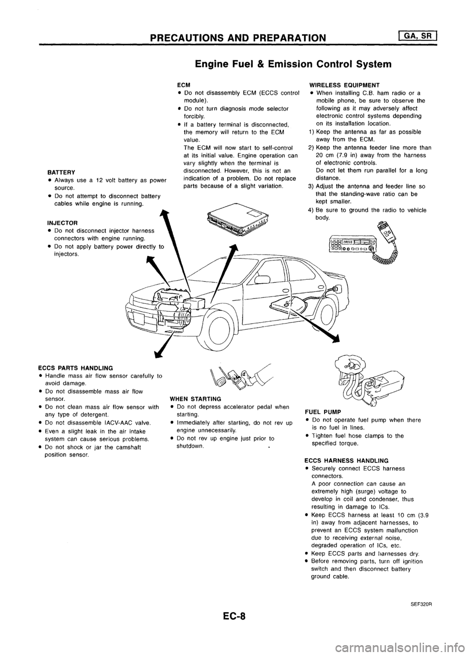
BATTERY • Always usea12 volt battery aspower
source.
• Do not attempt todisconnect battery
cables whileengine isrunning.
INJECTOR • Do not disconnect injectorharness
connectors withengine running.
• Do not apply battery powerdirectly to
injectors.
ECCS PARTS HANDLING
• Handle massairflow sensor carefully to
avoid damage.
• Do not disassemble massairflow
sensor.
• Do not clean massairflow sensor with
any type ofdetergent.
• Do not disassemble IACV-AACvalve.
• Even aslight leakinthe airintake
system cancause serious problems.
• Do not shock orjar the camshaft
position sensor. ECM
• Do not disassembly EGM(EGGS control
module).
• Do not turn diagnosis modeselector
forcibly.
• Ifabattery terminal isdisconnected,
the memory willreturn tothe ECM
value.
The ECM willnow start toself-control
at its initial value. Engine operation can
vary slightly whentheterminal is
disconnected. However,thisisnot an
indication ofaproblem. Donot replace
parts because ofaslight variation.
WHEN STARTING
• Do not depress accelerator pedalwhen
starting.
• Immediately afterstarting, donot revup
engine unnecessarily .
• Do not revupengine justprior to
shutdown.
EC-8 WIRELESS
EQUIPMENT
• When installing C.B.hamradio ora
mobile phone, besure toobserve the
following asitmay adversely affect
electronic controlsystems depending
on itsinstallation location.
1) Keep theantenna asfar aspossible
away fromtheEGM.
2) Keep theantenna feederlinemore than
20 em (7.9 in)away fromtheharness
of electronic controls.
Do not letthem runparallel foralong
distance.
3) Adjust theantenna andfeeder lineso
that thestanding-wave ratiocanbe
kept smaller.
4) Be sure toground theradio tovehicle
body.
FUEL PUMP
• Do not operate fuelpump whenthere
is no fuel inlines.
• Tighten fuelhose clamps tothe
specified torque.
ECCS HARNESS HANDLING
• Securely connectEGGSharness
connectors.
A poor connection cancause an
extremely high(surge) voltage to
develop incoil and condenser, thus
resulting indamage toICs .
• Keep ECGS harness atleast 10em (3.9
in) away fromadjacent harnesses, to
prevent anEGGS system malfunction
due toreceiving externalnoise,
degraded operation ofIGs, etc.
• Keep EGCS partsandharnesses dry.
• Before removing parts,turnoffignition
switch andthen disconnect battery
ground cable.
SEF320R
Page 736 of 1701
ENGINEANDEMISSION CONTROLOVERALLSYSTEM
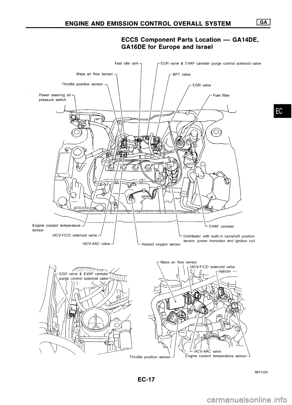
ECCS Component PartsLocation -GA14DE,
GA 16DE forEurope andIsrael
Mass airflow sensor
Throttle positionsensor
Power steering oil
pressure switch
Engine coolant temperature
sensor
IACV-FICDsolenoidvalve
IACV-AAC valveFast
idlecam EGRvalve
&
EVAP canister purgecontrol solenoid valve
Distributor withbuilt-in camshaft position
sensor, powertransistor andignition coil
•
Throttle positionsensor
SEF122R
EC-17
Page 737 of 1701
ENGINEANDEMISSION CONTROL OVERALLSYSTEM
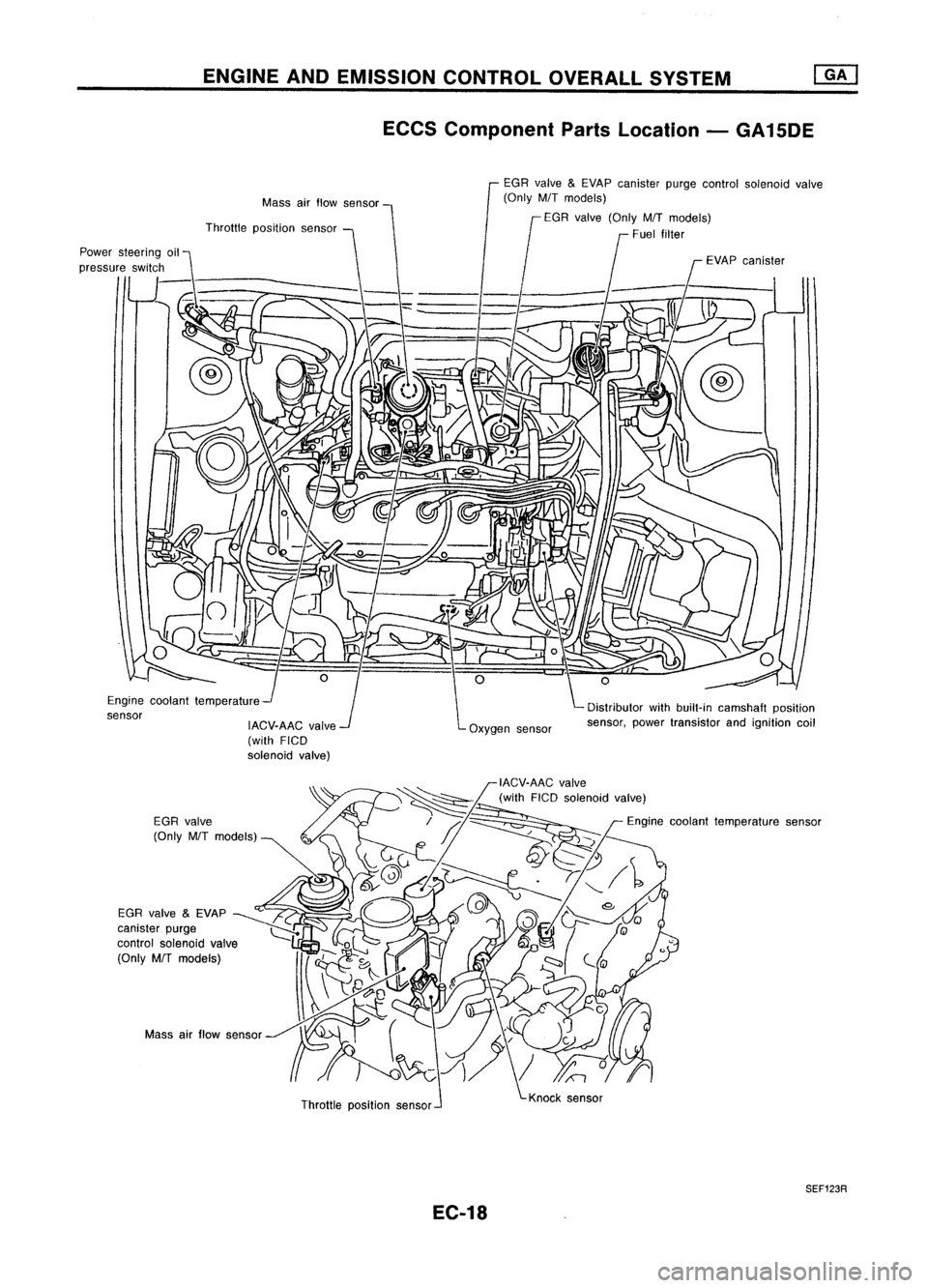
ECCS Component PartsLocation -GA15DE
Distributor withbuilt-in camshaft position
sensor, powertransistor andignition coil
EGR
valve
&
EVAP canister purgecontrol solenoid valve
(Only M/Tmodels)
f
EGR valve (Only M/Tmodels)
Fuel filter
EVAPcanister
Oxygen sensor
Mass
airflow sensor
IACV-AAC valve
(with FICD
solenoid valve)
Throttle
position sensor
Engine coolant temperature
sensor
Massairflow sensor
Throttleposition sensor
SEF123R
EC-18
Page 739 of 1701
ENGINEANDEMISSION CONTROL OVERALLSYSTEM
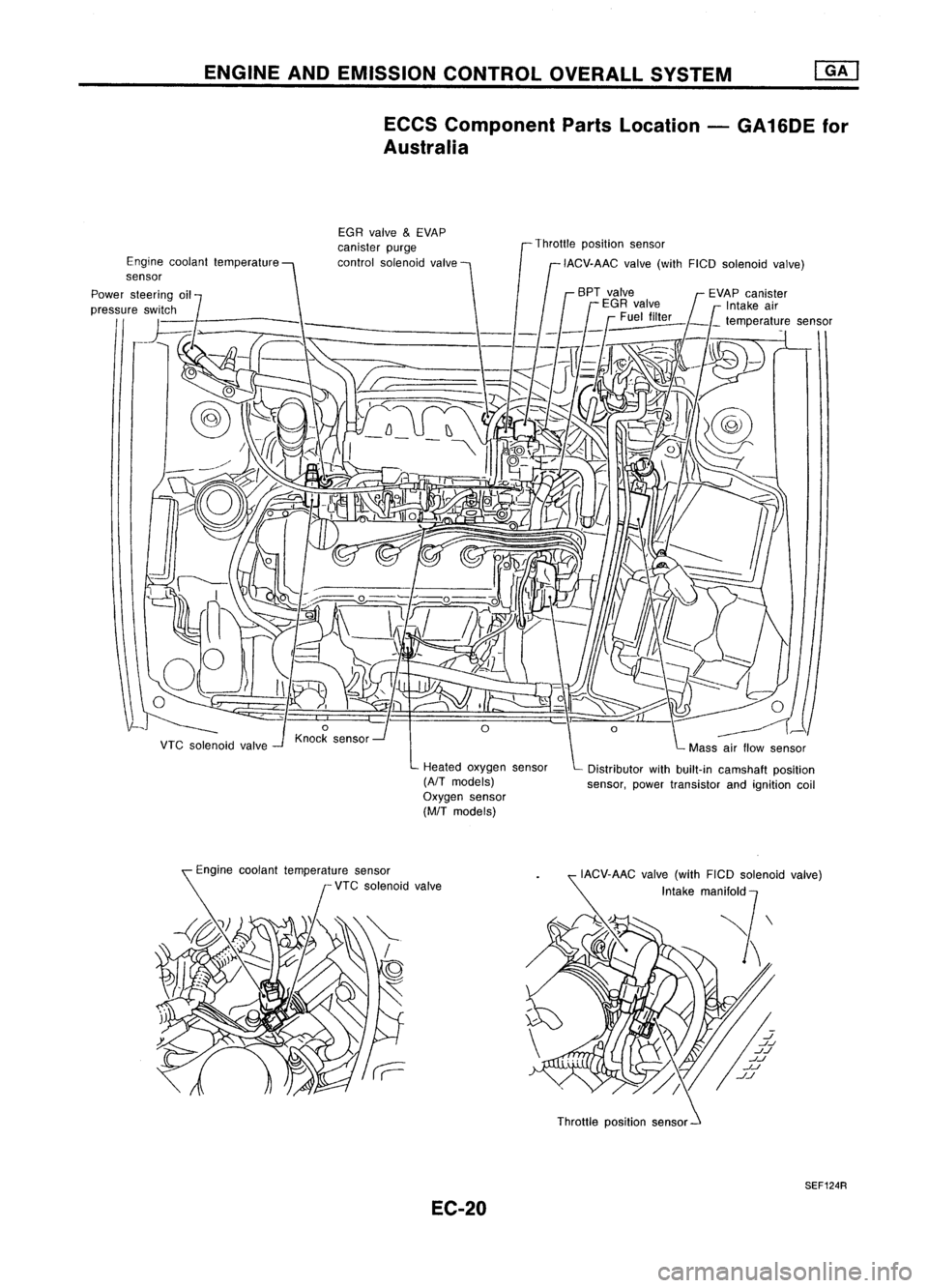
ECCS Component PartsLocation -GA16DE for
Australia
Heated oxygen sensor
(AfT
models)
Oxygen sensor
(MfT
models)
Engine
coolant temperature
sensor
VTCsolenoid valve EGR
valve
&
EVAP
canister purge
control solenoid valve Throttle
position sensor
IACV-AAC valve(withFICO solenoid valve)
Distributor withbuilt-in camshaft position
sensor, powertransistor andignition coil
Engine coolant temperature sensor
VTC solenoid valve
Throttlepositionsensor
SEF124R
EC-20
Page 742 of 1701
ENGINEANDEMISSION BASICCONTROL SYSTEMDESCRIPTION
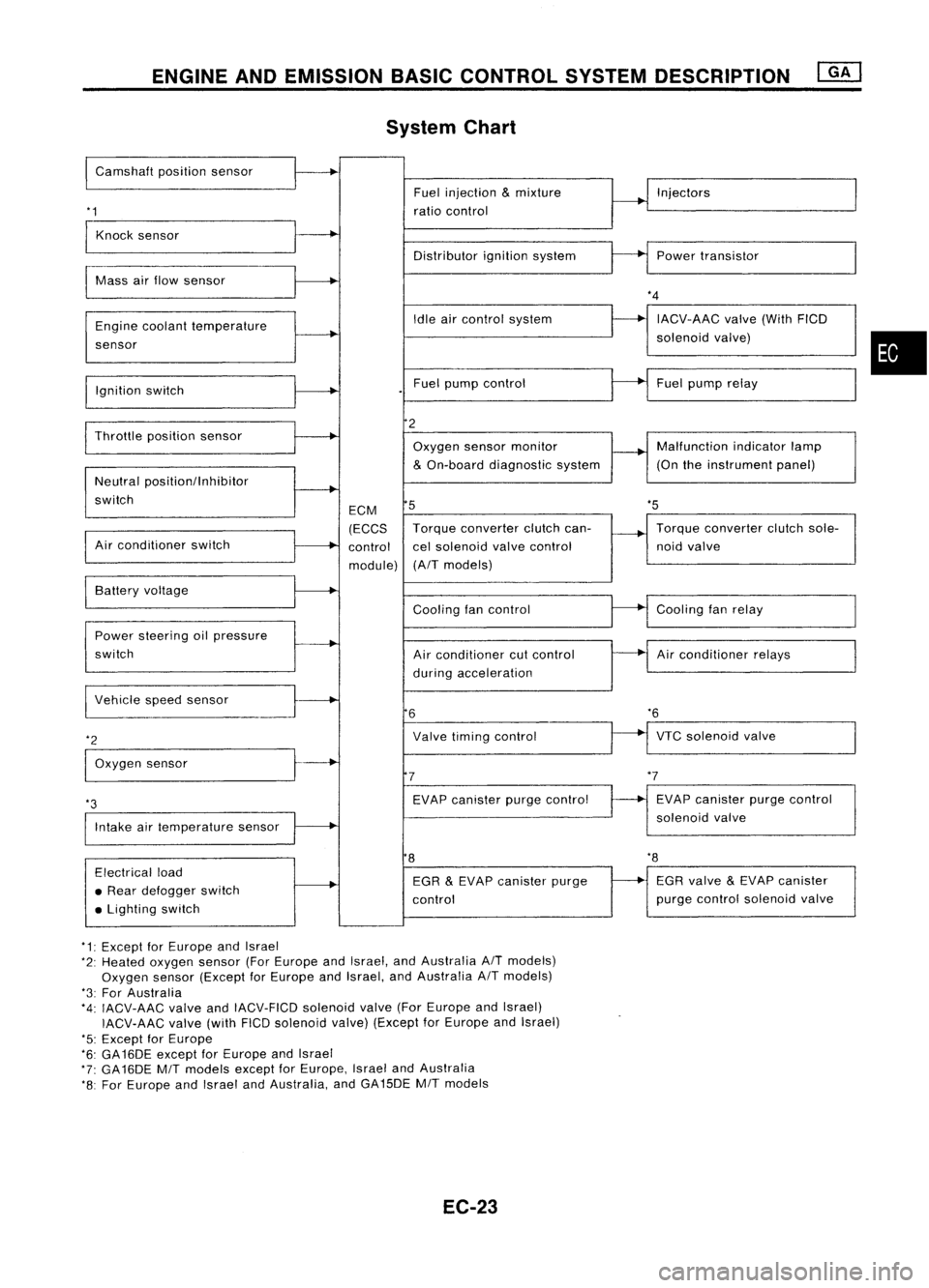
System Chart
I
Camshaft positionsensor
'1
Fuel
injection
&
mixture
ratio control Injectors
Knock sensor
Distributorignitionsystem Powertransistor
Mass airflow sensor
Engine coolant temperature
sensor
Ignition switch Idle
aircontrol system
Fuel pump control
*4
IACV-AAC valve(WithFICD
solenoid valve)
Fuel pump relay
•
'5
Throttle
positionsensor
Neutral positionllnhibitor
switch
Air conditioner switch ECM
(ECCS
control
module)
2
Oxygen sensormonitor
&
On-board diagnostic system
5
Torque converter clutchcan-
cel solenoid valvecontrol
(A/T models) Malfunction
indicatorlamp
(On theinstrument panel)
Torque converter clutchsole-
noid valve
VTC solenoid valve
*6
Air
conditioner relays
Cooling
fanrelay
EVAP canister purgecontrol
solenoid valve
Cooling
fancontrol
Air conditioner cutcontrol
during acceleration
Valve timing control
EVAP canister purgecontrol
7
6
Power
steering oilpressure
switch Battery
voltage
Intake airtemperature sensor
*3
I
Vehicle speedsensor
*2
I
Oxygen sensor
8
'8
Electrical load
• Rear defogger switch
• Lighting switch EGR
&
EVAP canister purge
control EGR
valve
&
EVAP canister
purge control solenoid valve
*1: Except forEurope andIsrael
*2: Heated oxygen sensor(ForEurope andIsrael, andAustralia A/Tmodels)
Oxygen sensor(Except forEurope andIsrael, andAustralia A/Tmodels)
*3: For Australia
*4: IACV-AAC valveandIACV-FICD solenoidvalve(ForEurope andIsrael)
IACV-AAC valve(withFICDsolenoid valve)(Except forEurope andIsrael)
'5: Except forEurope
*6: GA16DE exceptforEurope andIsrael
*7: GA16DE MITmodels exceptforEurope, IsraelandAustralia
*8: For Europe andIsrael andAustralia, andGA15DE MITmodels
EC-23
Page 759 of 1701
o
1:<
MONITOR
1<
NO FAIL
0
BASIC
SERVICE PROCEDURE
@KJ
Idle Speedllgnition Timing/IdleMixtureRatio
Adjustment (Cont'd)
@
CMPS.RPM (REF)
MIR
F/C
MNT 2000rpm
RICH
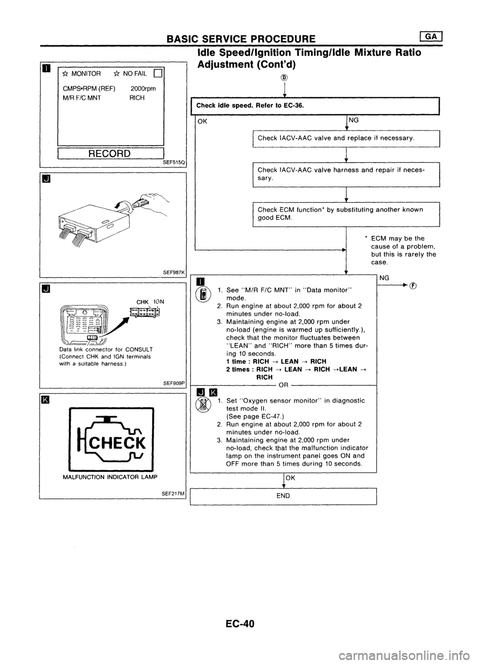
Checkidlespeed. Refer10EC-36.
OK NG
Check IACV-AAC valveandreplace ifnecessary.
__ R_E_C_O_R_D __
I
SEF515Q
CheckIACV-AAC valveharness andrepair ifneces-
sary.
Check ECMfunction- bysubstituting anotherknown
good ECM.
-ECM maybethe
cause ofaproblem,
but this israrely the
case.
SEF987K
(g~~~:: _
mJ
~~r
l~~~~V
-~
Data linkconnector forCONSULT
(Connect CHKandIGN terminals
with asuitable harness.)
SEF909P
MALFUNCTION INDICATORLAMP
SEF217M
o
(ij\E
1.See "MIA
F/C
MNT" in"Data monitor"
~ mode.
2. Run engine atabout 2,000rpmforabout 2
minutes underno-load.
3. Maintaining engineat2,000 rpmunder
no-load (engine iswarmed upsufficiently.),
check thatthemonitor fluctuates between
"LEAN" and"RICH" morethan5times dur-
ing 10seconds.
1 lime: RICH->LEAN ->RICH
2 limes: RICH->LEAN
->
RICH ->LEAN
->
RICH OR
Set "Oxygen sensormonitor" indiagnostic
test mode II.
(See page EC-47.)
2. Run engine atabout 2,000rpmforabout 2
minutes underno-load.
3. Maintaining engineat2,000 rpmunder
no-load, checkthatthemalfunction indicator
lamp onthe instrument panelgoesONand
OFF more than5times during 10seconds.
OK
END
EC-40 NG
Page 768 of 1701
ON-BOARDDIAGNOSTIC SYSTEMDESCRIPTION
CONSULT (Cont'd)
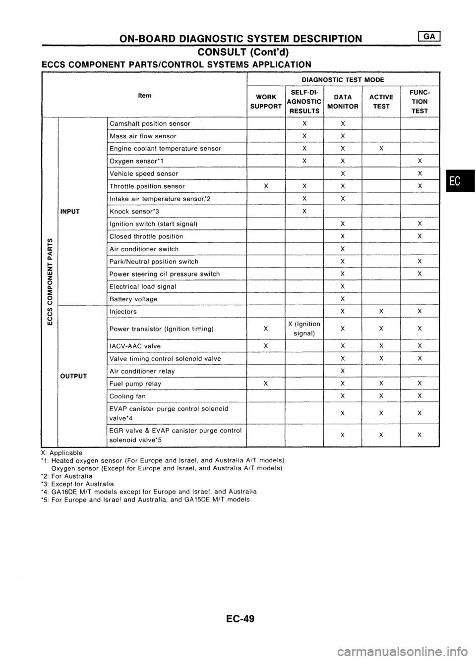
ECCS COMPONENT PARTS/CONTROL SYSTEMSAPPLICATION
DIAGNOSTICTESTMODE
Item WORKSELF-DI-
ACTIVEFUNC-
DATA
SUPPORT AGNOSTIC
MONITOR TION
TEST
RESULTS TEST
Camshaft positionsensor
X
X
Mass airflow sensor
X
X
Engine coolant temperature sensor
X
X X
Oxygen sensor'1
X
X X
Vehicle speedsensor
XX
Throttle positionsensor
XX
X X
Intake airtemperature sensor.'2
X
X
INPUT
Knock
sensor'3
X
Ignition switch(startsignal)
XX
I/)
Closed
throttle position
X
X
l-
ll:
Airconditioner switch
X
<
~
Park/Neutralpositionswitch
X
X
I-
Z
UJ
Powersteering oilpressure switch
XX
z
0
Electricalloadsignal
X
~
:E
0
Batteryvoltage
X
u
I/)
Injectors
XX
X
u
u
UJ
X(Ignition
Power transistor (Ignitiontiming) X X
XX
signal)
IACV-AAC valve X
XX
X
Valve timing control solenoid valve XX
X
OUTPUT
Air
conditioner relay
X
Fuel pump relay XX
XX
Cooling fan XX
X
EVAP canister purgecontrol solenoid
XX X
valve'4
EGR valve
&
EVAP canister purgecontrol
XX
X
solenoid valve'5
X: Applicable
'1: Heated oxygen sensor(ForEurope andIsrael, andAustralia AITmodels)
Oxygen sensor(Except forEurope andIsrael, andAustralia AITmodels)
'2: For Australia
'3: Except forAustralia
'4: GA16DE
MIT
models exceptforEurope andIsrael, andAustralia
'5: For Europe andIsrael andAustralia, andGA15DE
MIT
models
EC-49
•
Page 769 of 1701
ON-BOARDDIAGNOSTIC SYSTEMDESCRIPTION
CONSULT (Cont'd)
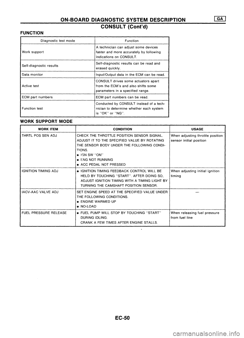
FUNCTION
Diagnostictestmode
Function
A technician canadjust somedevices
Work support
fasterandmore accurately byfollowing
indications onCONSULT.
Self-diagnostic results Self-diagnostic
resultscanberead and
erased quickly.
Data monitor
Input/Outputdatainthe ECM canberead.
CONSUL Tdrives someactuators apart
Active test
fromtheECM's andalso shifts some
parameters inaspecified range.
ECM partnumbers ECMpartnumbers canberead.
Conducted byCONSULT insteadofatech-
Function test
niciantodetermine whethereachsystem
is "OK" or"NG".
WORK SUPPORT MODE
WORK ITEM
CONDITION USAGE
THRTL POSSENADJ
CHECKTHETHROTTLE POSITIONSENSORSIGNAL. Whenadjusting throttleposition
ADJUST iTTO THE SPECIFIED VALUEBYROTATING
sensorinitialposition
THE SENSOR BODYUNDER THEFOLLOWiNG CONDI-
TIONS .
• IGN SW"ON"
• ENG NOTRUNNING
• ACC PEDAL NOTPRESSED
IGNITION TIMINGADJ
•IGNITION TIMINGFEEDBACK CONTROLWILLBE Whenadjusting initialignition
HELD BYTOUCHING "START".AFTERDOINGSO,
timing
ADJUST IGNITION TIMINGWITHATIMING LIGHTBY
TURNING THECAMSHAFT POSITIONSENSOR.
IACV-AAC VALVEADJ SETENGINE SPEEDATTHE SPECIFIED VALUEUNDER
-
THE FOllOWING CONDITIONS.
• ENGINE WARMED UP
• NO-LOAD
FUEL PRESSURE RELEASE •FUEL PUMP WillSTOP BYTOUCHING "START" Whenreleasing fuelpressure
DURING IDLING. fromfuelline
CRANK AFEW TIMES AFTER ENGINE STALLS.
EC-50