1995 NISSAN ALMERA N15 IACV-AAC
[x] Cancel search: IACV-AACPage 771 of 1701
![NISSAN ALMERA N15 1995 Service Manual ON-BOARDDIAGNOSTIC SYSTEMDESCRIPTION
CONSULT (Coni'd)
Monitored item
ECM
Main
[Unit] input
signals Description
Remarks
signals
LOAD SIGNAL •Indicates [ON/OFF] conditionfromthe
[ON/OFF] reardefo](/manual-img/5/57349/w960_57349-770.png "NISSAN ALMERA N15 1995 Service Manual ON-BOARDDIAGNOSTIC SYSTEMDESCRIPTION
CONSULT (Coni'd)
Monitored item
ECM
Main
[Unit] input
signals Description
Remarks
signals
LOAD SIGNAL •Indicates [ON/OFF] conditionfromthe
[ON/OFF] reardefo")
ON-BOARDDIAGNOSTIC SYSTEMDESCRIPTION
CONSULT (Coni'd)
Monitored item
ECM
Main
[Unit] input
signals Description
Remarks
signals
LOAD SIGNAL •Indicates [ON/OFF] conditionfromthe
[ON/OFF] reardefogger signaland/or lighting
switch.
0 0
ON:
Rear defogger isoperating
and/or lighting switchison.
OFF: Rear defogger isnot operating
and lighting switchisnot on.
INJ PULSE [msec]
0
•
Indicates theactual fuelinjection
•When theengine isstopped, acertain
pulse widthcompensated byECM computedvalueisindicated.
according tothe input signals.
IGN TIMING [BTDC]
0
•
Indicates theignition timingcomputed
by ECM according tothe input sig-
nals.
IACV-AACIV
[%]
•Indicates theidle aircontrol valve
0
(AAC
valve) control valuecomputed
by ECM according tothe input sig-
nals.
A/F ALPHA
[%]
•Indicates themean valueofthe air-
•When theengine isstopped, acertain
0
fuel
ratio feedback correction factor valueisindicated.
per cycle. •This data alsoincludes thedata for
the air-fuel ratiolearning control.
AIR COND RLY
0
•
Indicates theairconditioner relay
[ON/OFF] controlcondition (determined byECM
according tothe input signal).
COOLING FAN*2
•Indicates thecontrol condition ofthe
[ON/OFF] or[LOW/
coolingfans(determined byECM
HI/OFF]
0
according
tothe input signal).
ON ...Operating
LOW ...Operates atlow speed
HI ...Operates athigh speed
OFF ...Stopped
FUEL PUMP RLY
0
•
Indicates thefuel pump relaycontrol
[ON/OFF] conditiondetermined byECM accord-
ing tothe input signals.
VALVE TIMSOL*1
•The control condition ofthe valve tim-
[ON/OFF] ingsolenoid valve(determined by
ECM according tothe input signal) is
indicated.
ON ...VTC operating
OFF ...VTC notoperating
EGRC SOLIV (EVAP
•Indicates thecontrol condition ofthe
canister purgecon-
EVAPcanister purgecontrol solenoid
trol solenoid valve valveorEGR valve
&
EVAP canister
or EGR
&
EVAP can- purgecontrol solenoid valve(deter-
ister purge control
0
mined
byECM according tothe input
solenoid valve) signal).
[ON/OFF] ON'"EVAP canister purgeoperation
cut-off OFF ...EVAP canister purgeoperation
not cut-off
VOLTAGE •Voltage measured bythe voltage
[V] probe.
PULSE •Pulse width, frequency orduty cycle •Only "#"isdisplayed ifitem is
[msec] or[Hz] or measuredbythe pulse probe. unable
tobe measured .
[%]
•
Figures with"#"s aretemporary
ones. Theyarethesame figures as
an actual pieceofdata which wasjust
previously measured.
*1: GA16DE exceptforEurope andIsrael
*2: GA16DE engineA/Tmodels forEurope without heavydutykithave a2- step control [ON/OFF] system."LOW"and"HI"
are shown onCONSULT screentorepresent "ON"condition.
EC-52
Page 772 of 1701

ON-BOARDDIAGNOSTIC SYSTEMDESCRIPTION
CONSULT (Cont'd)
ACTIVE TESTMODE
TEST ITEM CONDITION JUDGEMENT
CHECKITEM(REMEDY)
• Engine: Returntothe original
•Harness andconnector
FUEL INJECTION trouble
condition If
trouble symptom disappears,
•Fuel injectors
• Change theamount offuel see
CHECK ITEM.
injection usingCONSULT . •
Oxygen sensor*1
• Engine: Afterwarming up,idle
IACV-AACIV the
engine.
Enginespeedchanges according •Harness andconnector
OPENING •
Change theIACV-AAC valve
tothe opening percent. •
IACV-AAC valve
opening percentusingCON-
SULT.
• Engine: Returntothe original
•Harness andconnector
ENG COOLANT trouble
condition
Iftrouble symptom disappears, •
Engine coolant temperature
TEMP •
Change theengine coolant
.
see CHECK ITEM. sensor
temperature indicationusing
•Fuel injectors
CONSULT.
• Engine: Returntothe original
trouble condition
Iftrouble symptom disappears,
IGNITION TIMING•
Timing light:Set •
Adjust initialignition timing
• Retard theignition timingusingsee
CHECK ITEM.
CONSULT .
• Engine: Afterwarming up,idle •
Harness andconnector
the engine. •
Compression
POWER •
A/C switch "OFF"
Enginerunsrough ordies . •
Injectors
BALANCE •
Shift lever "N" •
Power transistor
• Cut offeach injector signalone •
Spark plugs
at atime using CONSULT. •
Ignition coils
• Ignition switch:ON
COOLING FAN*3•
Turn thecooling fan"ON" and
Cooling fanmoves andstops. •
Harness andconnector
"OFF", or"LOW" and"HI" •
Cooling fanmotor
and "OFF" usingCONSULT .
• Ignition switch:ON(Engine
FUEL PUMP stopped)
Fuelpump relaymakes theoper- •Harness andconnector
• Turn thefuel pump relay"ON"
RELAY and"OFF" usingCONSULT ating
sound. •
Fuel pump relay
and listen tooperating sound.
EGRC SOLENOID
VALVE (EVAP canister
•Ignition switch:ON
purge control
•Turn solenoid valve"ON" and Solenoid
valvemakes anoperat- •
Harness andconnector
solenoid valveor
EGR valve
&
"OFF"
withtheCONSULT andingsound. •
Solenoid valve
EVAP canister listen
tooperating sound.
purge control
solenoid valve)
•Ignition switch:ON
VALVE TIMING •
Turn solenoid valve"ON" and Solenoid
valvemakes anoperat- •
Harness andconnector
SOL*2 "OFF"
usingCONSULT anding
sound. •
Solenoid valve
listen tooperating sound.
SELF-LEARNING •
Inthis test, thecoefficient ofself-learning controlmixture ratioreturns tothe original coefficient by
CONT touching
"CLEAR" onthe screen.
*1: Heated oxygen sensor(ForEurope andIsrael, andAustralia A/Tmodels)
Oxygen sensor(Except forEurope andIsrael, andAustralia A/Tmodels)
*2: GA16DE except forEurope andIsrael
*3: GA16DE engine A/Tmodels forEurope without heavydutykithave a2- step control [ON/OFF] system."LOW"and"HI"
are shown onCONSULT screentorepresent "ON"condition.
EC-53
•
Page 775 of 1701

ON-BOARDDIAGNOSTIC SYSTEMDESCRIPTION
CONSULT (Cont'd)
FUNCTION TEST
CONDITION JUDGEMENTCHECKITEM(REMEDY)
ITEM
•After warming up,idle the
engine .
• Injector operation ofeach •Injector circuit(Injector,
cylinder isstopped one harnessorconnector)
after another, andresult-
Difference inengine speedisgreater •
Ignition circuit(Spark
POWER BALANCE ant
change inengine rota-
than25rpm before andafter cutting off plug,
power transistor,
lion isexamined toevalu-
theinjector ofeach cylinder. ignition
coil,harness or
ate combustion ofeach connector)
cylinder. (Thisisonly dis- •Compression
played formodels wherea •
Valve timing
sequential multiportfuel
injection systemisused.)
• After warming up,idle the
•Harness andconnector
engine. •IACV-AAC valve
• IACV-AAC valvesystem is
Difference inengine speedisgreater •
Air passage restriction
IACV-AACIV testedbydetecting change
than150rpm between whenvalveopen- betweenairinlet and
SYSTEM inengine speedwhen
ingisat 80% andat20%. IACV-AACvalve
IACV-AAC valveopening
•IAS (Idle adjusting screw)
is changed to0%, 20%
and 80%. adjustment
EC-56
Page 783 of 1701
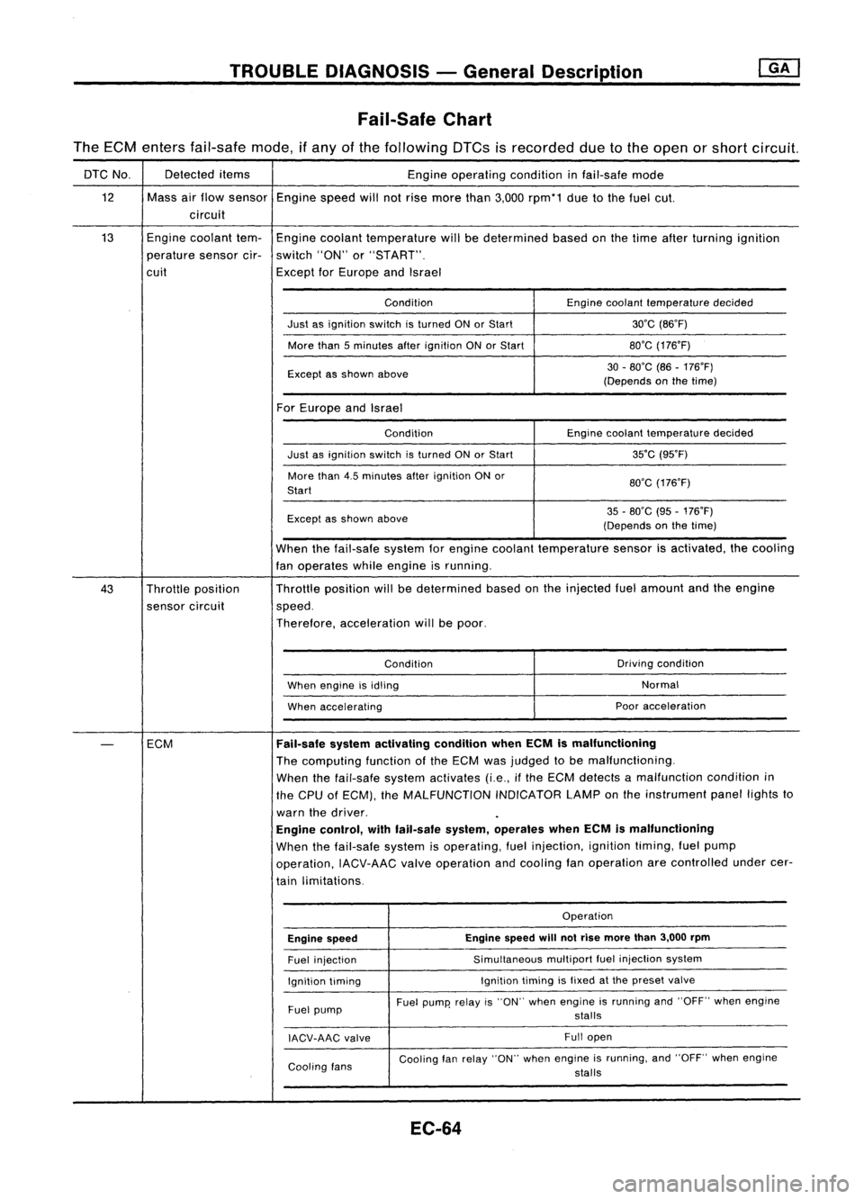
TROUBLEDIAGNOSIS -General Description
Fail-Safe Chart
The ECM enters fail-safe mode,ifany ofthe following DTCsisrecorded duetothe open orshort circuit.
DTC No. Detected
items
Engineoperating conditioninfail-safe mode
12 Massairflow sensor
Enginespeedwillnotrise more than3,000 rpm*1 duetothe fuel cut.
circuit
13 Engine
coolant tem-
Engine coolant temperature willbedetermined basedonthe time after turning ignition
perature sensorcir-switch "ON"or"START".
cuit ExceptforEurope andIsrael
Condition Enginecoolant temperature decided
Just asignition switchisturned ONorStart 30'C(B6'F)
More than5minutes afterignition ONorStart BO'G
(176'F)
Except asshown above 30
-BO'C (B6-176'F)
(Depends onthe time)
For Europe andIsrael
Condition Enginecoolant temperature decided
Just asignition switchisturned ONorStart 35'C
(95'F)
More than4.5minutes afterignition ONor
BO'G(176'F)
Start
Except asshown above 35
-BO'C (95-176'F)
(Depends onthe time)
When thefail-safe systemforengine coolant temperature sensorisactivated, thecooling
fan operates whileengine isrunning.
43 Throttle position Throttle
position willbedetermined basedonthe injected fuelamount andtheengine
sensor circuit speed.
Therefore, acceleration willbepoor.
Condition Driving
condition
When engine isidling Normal
When accelerating Poor
acceleration
-
ECM
Fail-safe
systemactivating conditionwhenECMismalfunctioning
The computing functionofthe ECM wasjudged tobe malfunctioning.
When thefail-safe systemactivates (i.e.,ifthe ECM detects amalfunction conditionin
the CPU ofECM), theMALFUNCTION INDICATORLAMPonthe instrument panellightsto
warn thedriver.
Engine control, withfail-safe system,operates whenECMismalfunctioning
When thefail-safe systemisoperating, fuelinjection, ignitiontiming,fuelpump
operation, IACV-AACvalveoperation andcooling fanoperation arecontrolled undercer-
tain limitations.
Operation
Engine speed Engine
speed
will
notrise more than3,000 rpm
Fuel injection Simultaneous
multipartfuelinjection system
Ignition timing Ignition
timingisfixed atthe preset valve
Fuel pump Fuel
pump' relayis"ON" when engine isrunning and"OFF" whenengine
stalls
IACV-AAG valve Full
open
Cooling fans Cooling
fanrelay "ON" whenengine isrunning, and"OFF" whenengine
stalls
EC-64
Page 790 of 1701
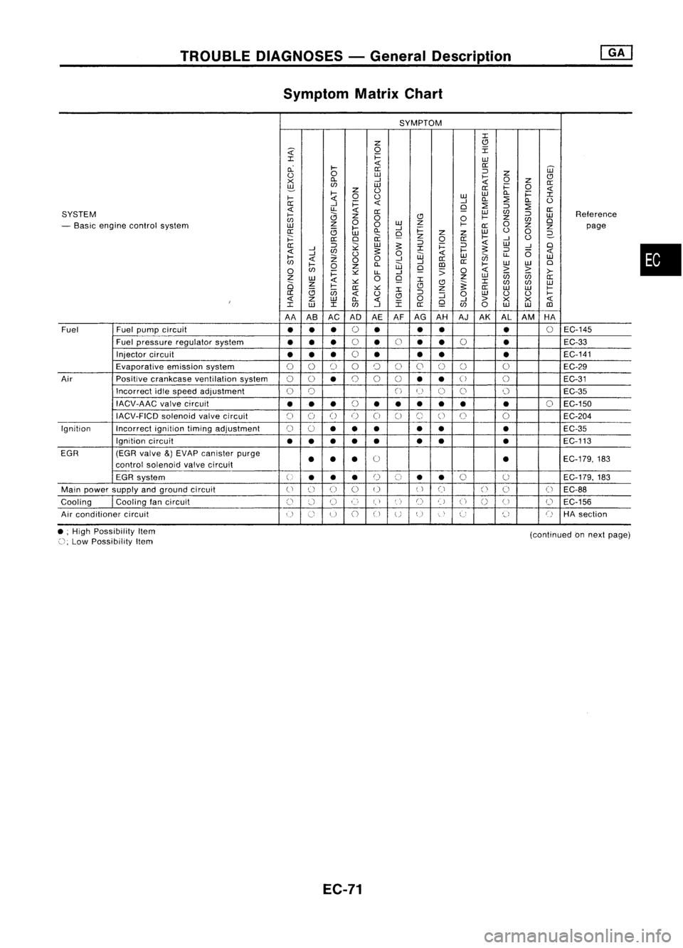
TROUBLEDIAGNOSES -General Description
Symptom MatrixChart
SYMPTOM
:c
z
(!l
~
0
I
:c
i=
w
cL
~
<{
0::
0::
='
W
<.)
0
w
~
z
CJ
x
Cl.
-I
0
Z
0::
~
en
w
i=
0
z
<.)
0::
<{
~
0
<.)
w
w
Cl.
i=
:c
~
-I
Cl.
::?
Cl.
<.)
0::
-I
i=
<{
Q
::?
=' ::?
<{
u..
<{
0::
SYSTEM
0::
W
en
='
Reterence
~
0
CJ
0
~
z
w
en
0
w
z
0
en
0
- Basic engine control system
w
z
0
~
0::
Z
Z
page
0::
<3
~
Cl.
-I
i=
w
<.)
0
w
Q
z
z
2-
j:::
0::
0
ii
z
0
0::
~
-I
<.)
0::
='
;;:
w
:s:
='
i=
='
<{
W
-I
0
<{
-I
en
:s:
:c
~
:s:
='
6
<{
-I
Z
<.)
0
w
<{
w
en
u..
w
~
<{
00
-I
0::
en
~
Cl.
W
-I
III
0::
~
W
W
0
0
en
0
z
Q
:;
0
<{
> >
i=
~
LL
-I
>-
Z
W
0
Q
z
w
U5 U5
0::
2i
z
<{
~ :c
(!l
~:c
en en
w
<3
~
0::
~
:c
CJ
z
0::
W W
~
0::
U5
<{
<.)
CJ
='
:J
0
w
<.)
<.)
~
I
<{
Z
W
Cl.
<{
0
Q
-I
>
X
X
<{
:c
w
:c
en
-I
:c
0::
en
0
w
W
III
AA AB AC ADAEAFAG
AH AJ
AK AL
AM HA
Fuel Fuel
pump circuit
••
•
0
•
•
•
•
0
EC-145
Fuel pressure regulator system
•••
0
•
0
•
•
0
•
EC-33
Injector circuit
•• •
0
• •
• •
EC-141
Evaporative emissionsystem
00
[)
00
()
0
0 0 0
EC-29
Air Positivecrankcase ventilation system
00
•
0
0
0
••
U
()
EC-31
Incorrect idlespeed adjustment
0
0
()
(~)
C)
0 0
EC-35
IACV-AAC valvecircuit
•••
(,
••• •• •
0
EC-150
~)
IACV-FICD solenoidvalvecircuit
C)
()
()
()
0
C)
(~,
()
0
0
EC-204
Ignition Incorrectignitiontimingadjustment
0
0
•• •
•
• •
EC-35
Ignition circuit
••
•
•
• •
•
•
EC-113
EGR (EGRvalve
&)
EVAP canister purge
0
EC-179,183
control soienoid valvecircuit
••
• •
EGR system
U
••
•
r)
(,)
•
•
0
0
EC-179.
183
Main power supply andground circuit
()
() ()
0 0
()
Ci
()
0
(
~
EC-88
Cooling
I
Cooling tancircuit
()
:.'-1
U
()
(,)
',)
C)
t)
U
n
(J
0
EC-156
u
Air conditioner circuit
()
Co
u
()
CJ
UU
"
,
C:
~,
()
HAsection
•
• ;High Possibility Item
(), Low Possibility Item
EC-71
(continued
onnext page)
Page 794 of 1701
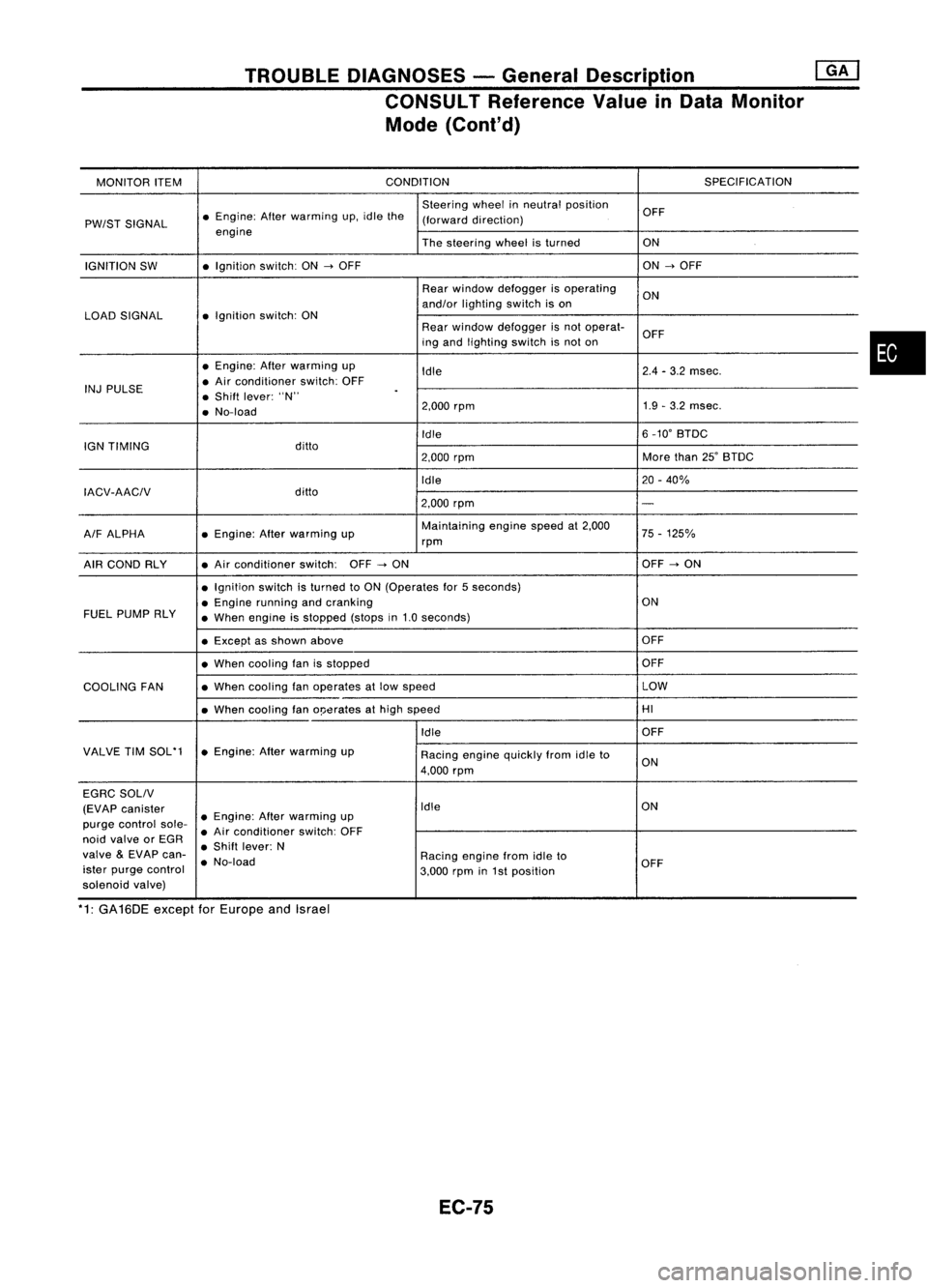
TROUBLEDIAGNOSES -General Description @KJ
CONSULT Reference ValueinData Monitor
Mode (Cont'd)
MONITOR ITEM CONDITION
SPECIFICATION
Steering wheelinneutral position
OFF
PW/ST SIGNAL •
Engine: Afterwarming up.idle the
(forward direction)
engine Thesteering wheelisturned ON
IGNITION SW •
Ignition switch:ON
-->
OFF ON
-->
OFF
Rear window defogger isoperating
ON
and/or lighting switchison
LOAD SIGNAL •
Ignition switch:ON
Rearwindow defogger isnot operat-
OFF
ing and lighting switchisnot on
• Engine: Afterwarming up
Idle 2.4
-3.2 msec.
INJ PULSE •
Air conditioner switch:OFF
• Shift lever: "N"
.
• No-load 2.000
rpm 1.9
-3.2 msec.
Idle 6
_10' BTDC
IGN TIMING ditto
2.000rpm More
than25'BTDC
Idle 20-40%
IACV-AACIV ditto
2.000rpm
-
A/F ALPHA •
Engine: Afterwarming up Maintaining
enginespeedat2.000
75-125%
rpm
AIR COND RLY •
Air conditioner switch:OFF
-->
ON OFF
-->
ON
• Ignition switchisturned toON (Operates for5seconds)
• Engine running andcranking ON
FUEL PUMP RLY
•When engine isstopped (stopsin1.0 seconds)
• Except asshown above OFF
• When cooling fanisstopped OFF
COOLING FAN •
When cooling fanoperates atlow speed LOW
• When cooling fano!Jerates athigh speed HI
Idle OFF
VALVE TIMSOL'1 •Engine: Afterwarming up
Racingenginequickly fromidleto
4.000 rpm ON
EGRC SOLIV
(EVAP canister Idle
ON
purge control sole-•
Engine: Afterwarming up
• Air conditioner switch:OFF
noid valve orEGR
•Shift lever: N
valve
&
EVAP can-
•No-load Racing
enginefromidleto
ister purge control
3.000rpmin1st position OFF
solenoid valve)
*1: GA16DE exceptforEurope andIsrael
EC-75
•
Page 800 of 1701
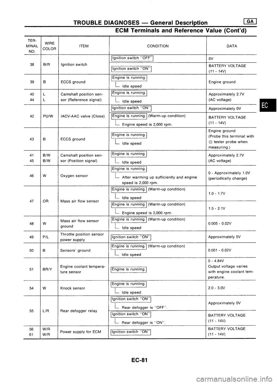
TROUBLEDIAGNOSES -General Description ~
ECM Terminals andReference Value(Cont'd)
TER-
MINAL WIRE
CONDITION
ITEM DATA
NO. COLOR
Ilgnitionswitch"OFF"1
OV
38 BIR
Ignitionswitch
BATTERYVOLTAGE
llgnition switch"ON"!
(11-14V)
39 B ECCSground
I
Engine isrunning.
I
Engineground
L
Idle speed
40 l Camshaft positionsen- I
Engine isrunning. I
Approximately2.7V
44 l sor(Reference signal)
L
Idle speed (AC
voltage)
i'gnition switch"ON'"
ApproximatelyOV
42 PUlW IACV-AAC valve(Close) IEngine
isrunning.
I
(Warm-up condition)
BATTERYVOLTAGE
L
Engine speedis2,000 rpm. (11
-14V)
I
Engine isrunning.
I
Engine
ground
43 B ECCS
ground (Probe
thisterminal with
L
Idle speed
e
tester probe when
measuring.)
41
B/W
Camshaft positionsen- IEngine
isrunning.1
Approximately2.7V
45
B/W
sor
(Position signal)
L
Idle speed (AC
voltage)
I
Engine isrunning.
I
o-
Approximately 1.0V
46 W Oxygen
sensor
L
After warming upsufficiently andengine
(periodicallychange)
speed is2,000 rpm.
I
Engine isrunning.
I
(Warm-up condition)
1.0-1.7V
L
Idle speed
47 OR Massairflow sensor
I
Engine isrunning.! (Warm-up condition)
L
Engine speedis2,000 rpm. 1.5
-2.1V
48 W Mass
airflow sensor
I
Engine isrunning. I(Warm-up condition)
0.005-0.02V
ground
L
Idle speed
49 P/l Throttle
position sensor
j!gnitionswitch"ON"I Approximately
5V
power supply
50 B Sensors'
ground
I
Engine isrunning.
I
(Warm-up condition)
0.001-0.02V
L
Idle speed
0-4.84V
51 BRIY Engine
coolant tempera-
1Engine isrunning.
I
Output
voltage varies
ture sensor with
engine coolant tem-
perature.
54 W Knock
sensor
I
Engine isrunning.!
2.0-3.0V
L
Idle speed
Ilgnition switch"ON'"
ApproximatelyOV
L
Rear defogger is"OFF".
55 LlR Rear
defogger relay
Ilgnitionswitch"ON"I
BATTERY VOLTAGE
L
Rear defogger is"ON". (11
-14V)
56
W/R
Ilgnitionswitch"ON"I BA
TTERY VOLTAGE
61
W/R
Power
supply forECM
(11-14V)
EC-81
•
Page 801 of 1701
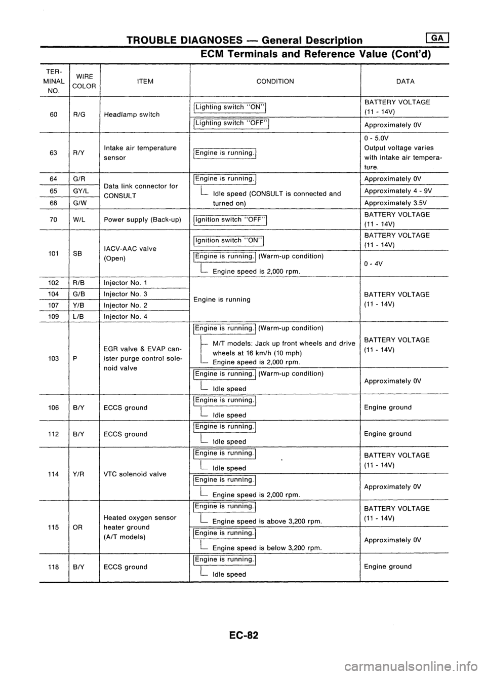
TROUBLEDIAGNOSES -General Description ~
ECM Terminals andReference Value(Conl'd)
TER- WIRE
MINAL COLOR ITEM
CONDITION DATA
NO.
ILightingswitch"ON"I BATTERY
VOLTAGE
60
RIG
Headlamp switch (11
-14V)
ILighting switch"OFF"I
ApproximatelyOV
0- 5.0V
63 RIY Intake
airtemperature
I
Engine isrunning.
I
Output
voltage varies
sensor with
intake airtempera-
ture.
64 GIR
I
Engine isrunning.
I
Approximately
OV
65 GY/L Data
linkconnector for
L
Idle speed (CONSULT isconnected andApproximately
4-9V
CONSULT
68
GIW
turnedon) Approximately
3.5V
I,gnition switch"OFF"
I
BATTERY
VOLTAGE
70
W/L
Powersupply (Back-up)
(11-14V)
Ilgnition switch"ON"I BA
TTERY VOLTAGE
IACV-AAC valve (11
-14V)
101 SS
(Open)
I
Engine isrunning.
I
(Warm-up condition)
L
Engine speedis2,000 rpm. 0-
4V
102 RIB Injector
No.1
104
GIS
InjectorNo.3
BATTERYVOLTAGE
107 YIB InjectorNo.2 Engine
isrunning
(11-14V)
109 LIB Injector
No.4
IEngineisrunning.
I
(Warm-up condition)
~ MIT
models: Jackupfront wheels anddrive BATTERY
VOLTAGE
EGR valve
&
EVAP can-
L
wheels at16 kmlh (10mph) (11
-14V)
103 P
.isterpurge control sole-
Enginespeedis2,000 rpm.
noid valve
IEngineisrunning.
I
(Warm-up condition)
L
Idle speed Approximately
OV
106 BIY ECCSground
I
Engine isrunning.
I
Engineground
L
Idle speed
112 BIY ECCS
ground
I
Engine isrunning.
I
Engineground
L
Idle speed
I Engine isrunning.
I
BATTERYVOLTAGE
L
Idle speed
.
(11-14V)
114 YIR VTCsolenoid valve
I
Engine isrunning.
I
L
Engine speedis2,000 rpm. Approximately
OV
IEngine isrunning.
I
BATTERYVOLTAGE
Heated oxygen sensor
L
Engine speedisabove 3,200rpm. (11
-14V)
115 OR heaterground
IEngine isrunning.
I
(A/T models)
ApproximatelyOV
L
Engine speedisbelow 3,200rpm.
118 SlY ECCS
ground
I
Engine isrunning.
I
Engineground
L
Idle speed
EC-82