Page 639 of 1701
LOCATIONOFELECTRICAL UNITS
Passenger Compartment
LHD MODELS
Rearwindow defogger timer
(With daytime lightsystem)
Warning buzzerunit
Combination flasherunit
Junction boxNO.2 (Joint connectors)
Stop lamp switch
Mirror defogger relay
(With daytime lightsystem)
Sun roofrelay (Without powerwindow)
Power window relay(With power window)
Front foglamp relay
SMJ (Main harness-
engine roomharness) NATS
IMMU (Gasoline engine)
Door locktimer
ABS control unit
Front wiper amplifier
SMJ (Main harness-
front doorharness)
SMJ (Main harness-
front doorharness)
Rear wiper amplifier
Daytime lightunit
Circuit breaker
Fuel pump relay
(Gasoline engine)
Fuse block
(JIB)
Ignition relay
Blower relay
Accessory relay Air
bag diagnosis sensorunit
(With dualairbag system)
ECM (ECCS control module) (Gasoline engine)
ECM (Engine controlmodule) (Dieselengine)
ECCS relay(Gasoline engine)
EL-267 HEL
150
•
Page 640 of 1701
RHOMODELS LOCATION
OFELECTRICAL UNITS
Passenger Compartment (Cont'd)
Warning buzzerunit
ABS control unit
Front wiper amplifier
SMJ (Main harness-
front doorharness) NATS
IMMU (Gasoline engineforEurope)
Rear wiper amplifier
Combination flasherunit
Stop lamp switch
Sun roolrelay (Without powerwindow)
Power window relay(With power window)
Front foglamp relay
SMJ (Main harness-
engine roomharness)
EGM (EGGS controlmodule) (Gasoline engine)
EGM (Engine controlmodule) (Dieselengine)
EGGS relay(Gasoline engine)
EL-268 SMJ
(Main harness-
Iront doorharness)
Circuit breaker
Fuel pump relay
(Gasoline engine)
Fuse block
(JIB)
Accessory relay
Blower relay
Ignition relay
HEL151
Page 684 of 1701
PRECAUTIONSANDPREPARATION
Precautions
• When installing rubberparts,finaltightening mustbecar-
ried outunder unladen condition* withtires onground.
*: Fuel, radiator coolantandengine oilfull. Spare tire,
jack,
hand tools andmats indesignated positions.
• After installing removedsuspension parts,check wheel
alignment andadjust ifnecessary.
• Use flare nutwrench whenremoving orinstalling brake
tubes.
• Always torquebrakelineswhen installing.
Tool number
Tool name
SBR820B
Special Service Tools
Description
HT72520000
Ball joint remover Removing
tie-rodouterendandlower ball
joint
NT146
HT71780000
Spring compressor
ST35652000
Strut attachment
NT144
Removing
andinstalling coilspring
Fixing strutassembly
NT145
GG94310000
Flare nuttorque wrench
KV38106700
KV381 06800
Differential sideoilseal
protector
NT406
NT147
FA-2
Removing
andinstalling brakepiping
a:
10mm (0.39 in)
Installing driveshaft
LH: KV38106700
RH: KV38106800
Page 686 of 1701
FRONTSUSPENSION SYSTEM
SEC. 391-400-401
When installing rubberparts,finaltightening mustbecarried outunder unladen condition" withtires onground .
• Fuel, radiator coolantandengine oilfull. Spare tire,jack, hand tools andmats indesignated positions.
~~25.29
~ (2.5•3.0, 18•22)
\ \
...
5
~ 98•118 (10•12, 72•87)
Front
to.J:
N. m (kg-m, ft-Ib)
SFA715B
CD
Suspension member
@
Stabilizer bar
@
Drive shaft
@
Coilspring
@
Strut assembly
@
Knuckle
FA-4
(J)
Transverse link
@
Front struttower bar
Page 688 of 1701

ON-VEHICLESERVICE
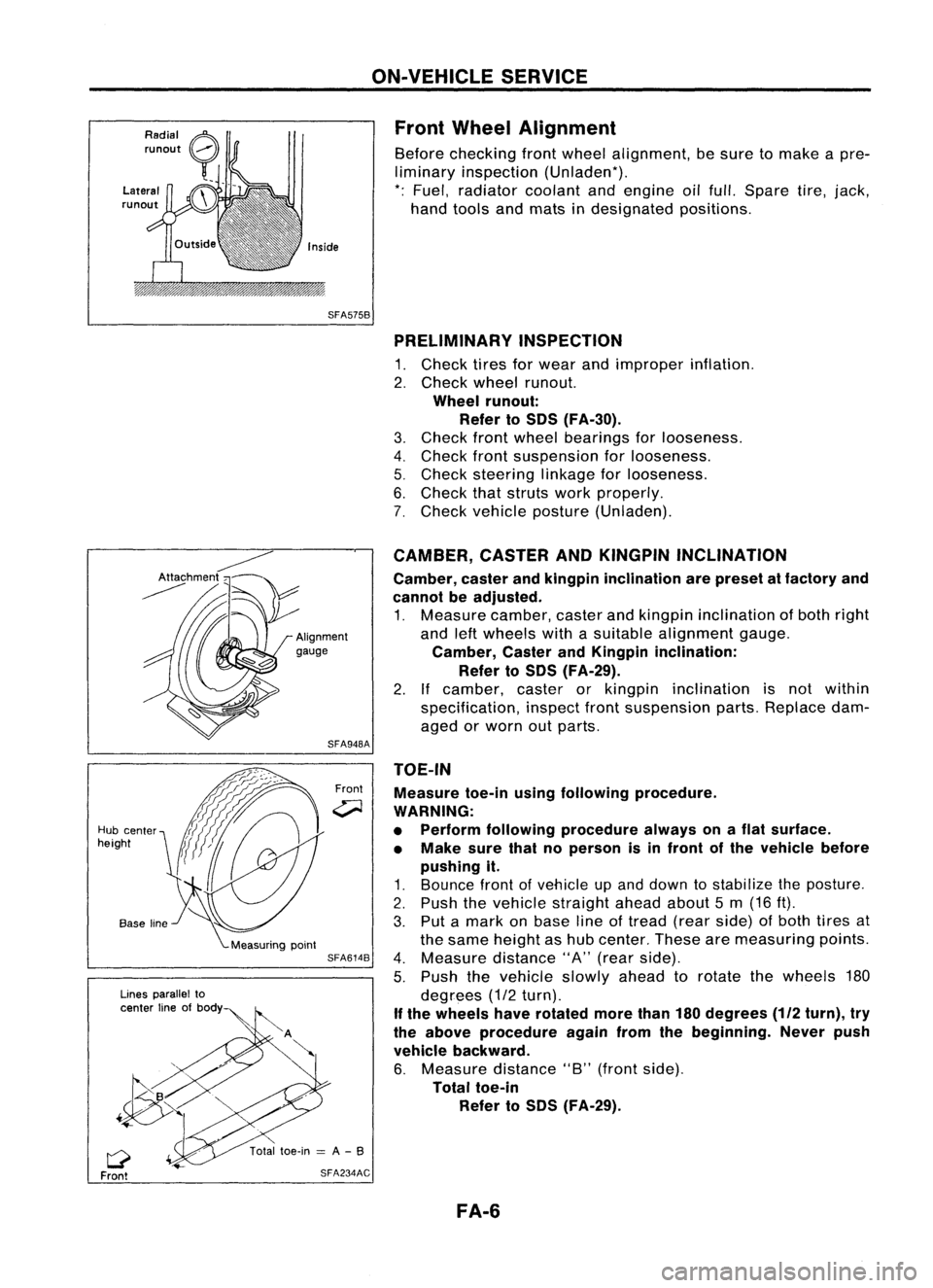
Front Wheel Alignment
Before checking frontwheel alignment, besure tomake apre-
liminary inspection (Unladen*).
*: Fuel, radiator coolantandengine oilfull. Spare tire,jack,
hand tools andmats indesignated positions.
SFA575B PRELIMINARY INSPECTION
1. Check tiresforwear andimproper inflation.
2. Check wheelrunout.
Wheel runout:
Refer toSOS (FA-30).
3. Check frontwheel bearings forlooseness.
4. Check frontsuspension forlooseness.
5. Check steering linkageforlooseness.
6. Check thatstruts workproperly.
7. Check vehicle posture (Unladen).
TOE-IN Measure toe-inusingfollowing procedure.
WARNING:
• Perform following procedure alwaysonaflat surface.
• Make surethatnoperson isin front ofthe vehicle before
pushing it.
1. Bounce frontofvehicle upand down tostabilize theposture.
2. Push thevehicle straight aheadabout5m (16 ft).
3. Put amark onbase lineoftread (rearside) ofboth tires at
the same height ashub center. Thesearemeasuring points.
4. Measure distance"A"(rear side).
5. Push thevehicle slowlyaheadtorotate thewheels 180
degrees (1/2turn).
If the wheels haverotated morethan180degrees
(112
turn), try
the above procedure againfromthebeginning. Neverpush
vehicle backward.
6. Measure distance"B"(front side).
Total toe-in
Refer toSOS (FA-29).
CAMBER,
CASTERANDKINGPIN INCLINATION
Camber, casterandkingpin inclination arepreset atfactory and
cannot beadjusted.
1. Measure camber,casterandkingpin inclination ofboth right
and leftwheels withasuitable alignment gauge.
Camber, CasterandKingpin inclination:
Refer toSOS (FA-29).
2. Ifcamber, casterorkingpin inclination isnot within
specification, inspectfrontsuspension parts.Replace dam-
aged orworn outparts.
Front
SFA948A
SFA614B
SFA234AC
Lines
parallel to
center lineofbody
Q
Front
Hub
center
height
FA-6
Page 706 of 1701
SEC.391.400.401
When installing rubberparts,finaltightening
must becarried outunder unladen condition'
with tires onground.
• Fuel, radiator coolanta'1dengine 011full.
Spare tire,Jack, hand toolsandmats In
designated positions.
@
~
L.~
(3.2-4.3, 23•31)
Front
CD
Spacer
@
Strut mounting insulator
@
Strut mounting insulator
bracket
@
Thrust bearing
@
Upper spring seat
@
Upper spring rubber seat
(J)
Bumper rubber
@
Coilspring
FRONT
SUSPENSION
@
Lower spring rubber seat
@)
Strut assembly
@
Suspension member
@
Stabilizer bar
@
Stabilizer clamp
@
Connecting rod
@
Transverse link
@
Compression rodclamp
@
Drive shaft
FA-24
~~
59.74
~~~.~ ::'.4:9- 54)
o
(2.5_3.0,
18 -22)
~
~~
~ ~
9=:
~~
-----J
/~18-24
1/ ~
(1.8.2.4,13.17)
~. @
&1
(@
~ J~!~5
(20-28, 145 •203)
~ 59•74 (6.0 -7.5, 43•54)
SFA624B
@
Knuckle
@
Cotter pin
@)
ABS sensor
@
Plain washer
@
Wheel bearing locknut
@
Insulator
@
Adjusting cap
@
Cotter pin
Page 711 of 1701

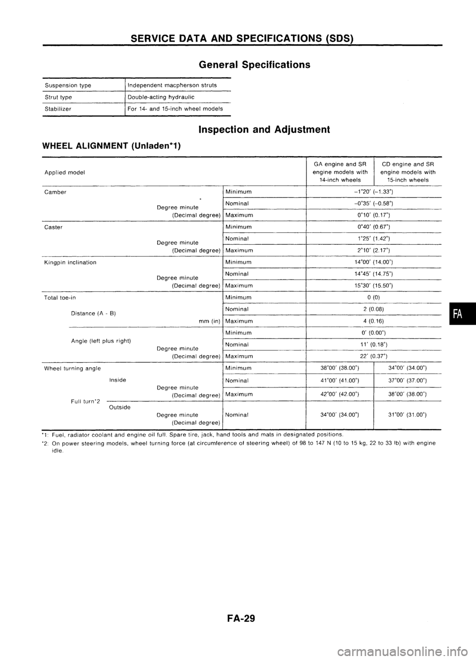
SERVICEDATAANDSPECIFICATIONS (50S)
General Specifications
Suspension type
Strut type
Stabilizer Independent
macpherson struts
Double-acting hydraulic
For 14-and 15-inch wheelmodels
Inspection andAdjustment
WHEEL ALIGNMENT (Unladen*1)
GAengine andSR CDengine andSR
Applied model engine
models with enginemodels with
14-inch wheels 15-inchwheels
Camber Minimum
-no'
(-1.33')
.
Degree minute Nominal
-0'35'
(-0.58')
(Decimal degree)Maximum 0'10'
(0.1
r)
Caster Minimum
0'40'(0.6r)
Degree minute Nominal
1
'25' (1.42')
(Decimal degree)Maximum 2'10'
(217")
Kingpin inclination Minimum14'00'
(14.00')
Degree minute Nominal
14'45'
(14.75')
(Decimal degree)Maximum 15'30'
(15.50')
Total toe-in Minimum0(0)
Distance (A-B) Nominal
2(008)
mm (in) Maximum 4(0.16)
Minimum 0'
(0.00')
Angle (leftplus right)
Nominal 11'
(0.18')
Degree minute
(Decimal degree)Maximum 22'
(0.37")
Wheel turning angle Minimum
38'00'
(38.00') 34'00'(34.00')
Inside Nominal4nO'
(41.00')
3rOO'(37.00')
Degree minute
(Decimal degree)Maximum
42'00'
(42.00')
38'00'(38.00')
Full (urn'2
Outside
Degreeminute Nominal 34'00'
(34.00') 31'00'(3100')
(Decimal degree)
'1' Fuel, radiator coolantandengine oilfull. Spare tire,jack, hand tools andmats indesignated positions.
'2: On power steering models,wheelturning force(atcircumference ofsteering wheel)of98 to147 N(10 to15 kg, 22to33 Ib)with engine
idle
FA-29
•
Page 713 of 1701
ACCELERATORCONTROL,FUEL
&
EXHAUST SYSTEMS
SECTION
FE
CONTENTS
ACCELERATOR CONTROLSySTEM 2FUELSYSTEM 3
Adjusting Accelerator Wire 2FuelPump andGauge 4
EXHAUST SySTEM
5
•