1995 NISSAN ALMERA N15 airbag off
[x] Cancel search: airbag offPage 1631 of 1701
SUPPLEMENTALRESTRAINTSYSTEM(SRS)
Visually checkSRScomponents
Diagnosis sensorunit
Check diagnosis sensorunitand bracket fordents, cracks
or deformities.
Check connectors fordamage, andterminals fordeformi-
ties.
Air bag module andsteering wheel
Remove airbag module fromsteering wheelorinstrument
panel. Check harness coverandconnectors fordamage,
terminals fordeformities, andharness forbinding.
Install driversideairbag module tosteering wheeltocheck
fit or alignment withthewheel.
Check steering wheelforexcessive freeplay.
For dual airbag system, installpassenger sideairbag
module toinstrument paneltocheck fitor alignment withthe
instrument panel.
Maintenance
Items
1. Check "AIRBAG" warning lampoperation
After turning ignition keyto"ON" position, "AIRBAG"
warning lampilluminates. The"AIR BAG" warning lamp
will turn offafter about 7seconds ifno malfunction is
detected. If any ofthe following airbag warning lampconditions
occur, immediately checktheairbag system. RefertoRS-32
and 43for details.
The warning lampdoesnotilluminate whentheignition
switch isturned "ON".
The warning lampdoesnotturn offabout 7seconds after
the ignition switchisturned "ON".
The warning lampturns offabout 7seconds aftertheigni-
tion switch isturned "ON",butitturns onorflashes again.
•
MRS115A
•
•
2. (1)
•
•
(2)
•
•
•
•
(3) Spiral cable
• Check spiralcablefordents, cracks, ordeformities.
• Check connectors andprotective tapefordamage.
• Check steering wheelfornoise, binding orheavy operation. •
(4) Main harness andairbag harness (Fordual airbag system
only)
• Check connectors forpoor connections, damage,andtermi-
nals fordeformities.
• Check harnesses forbinding, chafingorcut.
CAUTION: Replace previously usedscrews withnewones.
RS-11
Page 1632 of 1701
SUPPLEMENTALRESTRAINTSYSTEM(SRS)
Removal andInstallation -Diagnosis Sensor
Unit
CAUTION:
• Before servicing SRS,turntheignition switchoff,disconnect bothbattery cablesandwait foratleast
10 minutes.
• The special boltsarecoated withbonding agentwhiletheother boltisfor ground. Donot use old
bolts afterremoval; replacewithnewones.
• For single airbag system, donot separate diagnosis sensorunitfrom steering wheel.
• For dual airbag system, checkdiagnosis sensorunitforproper installation.
• Check diagnosis sensorunittoensure theyarefree ofdeformities, dents,cracks orrust. Ifthey show
any visible signsofdamage, replacethemwithnewones.
• Check diagnosis sensorunitbrackets toensure theyarefree ofdeformities orrust.
• Always workfromtheside ofair bag module.
• Replace diagnosis sensorunitifithas been dropped orsustained animpact.
SEC. 253~
IT
r
Grou~? bolt~
G ~~ ~
Forward mark
Fr?nt
_--I
d--!
Dia~no:iS senSlrunit
!
Special bOIt~ -
t"'J
15-25 N.m
(1.5 •2.5 kg-m,
11-
18 ft-Ib)
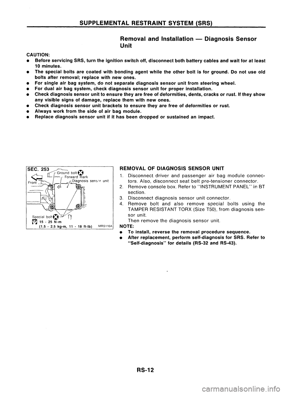
MRS116A REMOVAL
OFDIAGNOSIS SENSORUNIT
1. Disconnect driverandpassenger airbag module connec-
tors. Also, disconnect seatbeltpre-tensioner connector.
2. Remove consolebox.Refer to"INSTRUMENT PANEL"in8T
section.
3. Disconnect diagnosissensorunitconnector.
4. Remove boltandalso remove specialboltsusing the
TAMPER RESISTANT TORX(SizeT50),fromdiagnosis sen-
sor unit.
Then remove thediagnosis sensorunit.
NOTE:
• Toinstall, reverse theremoval procedure sequence.
• After replacement, performself-diagnosis forSRS. Refer to
"Self-diagnosis" fordetails (RS-32andRS-43).
RS-12
Page 1635 of 1701
SUPPLEMENTALRESTRAINTSYSTEM(SRS)
Removal -Air Bag Module andSpiral Cable
CAUTION:
• Before servicing SRS,turntheignition switchoff,discon-
nect both battery cablesandwait foratleast 10minutes.
• Always workfromtheside ofair bag module.
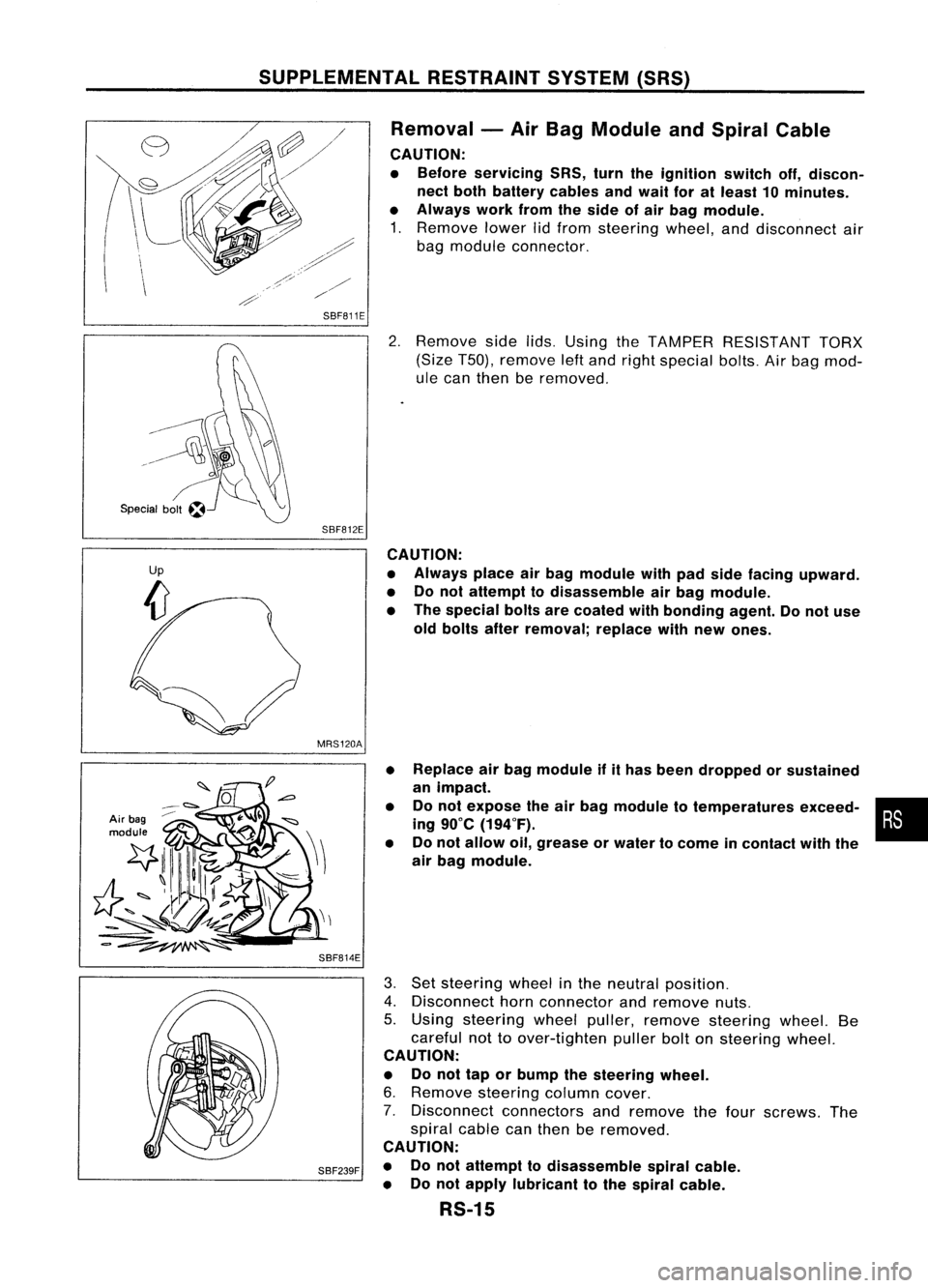
1. Remove lowerlidfrom steering wheel,anddisconnect air
bag module connector.
SBF811E
2.Remove sidelids.Using theTAMPER RESISTANT TORX
(Size T50), remove leftand right special bolts.Airbag mod-
ule can then beremoved.
SBF812E CAUTION:
• Always placeairbag module withpadside facing upward.
• Donot attempt todisassemble airbag module.
• The special boltsarecoated withbonding agent.Donot use
old bolts afterremoval; replacewithnew ones.
MRS120A
Air bag
module
SBF814E•
•
• Replace
airbag module ifithas been dropped orsustained
an impact.
Do not expose theairbag module totemperatures exceed-•
•
ing 90°C (194°F).
Do not allow oil,grease orwater tocome incontact withthe
air bag module.
SBF239F
3.
Set steering wheelinthe neutral position.
4. Disconnect hornconnector andremove nuts.
5. Using steering wheelpuller, remove steering wheel.Be
careful nottoover-tighten pullerboltonsteering wheel.
CAUTION:
• Donot tap orbump thesteering wheel.
6. Remove steering columncover.
7. Disconnect connectorsandremove thefour screws. The
spiral cablecanthen beremoved.
CAUTION:
• Donot attempt todisassemble spiralcable.
• Donot apply lubricant tothe spiral cable.
RS-15
Page 1636 of 1701
SUPPLEMENTALRESTRAINTSYSTEM(SRS)
Removal -Front Passenger AirBag Module
(Dual AirBag System)
CAUTION:
• Before servicing SRS,turntheignition switchoff,discon-
nect both battery cablesandwait foratleast 10minutes.
• Always workfromtheside ofor under airbag module.
1. Open theglove boxlid.
2. Disconnect inflatorconnector frombody harness airbag
connector.
3. Remove gloveboxassembly. Referto"INSTRUMENT
PANEL" inBT section fordetails.
Air bag
module
4.
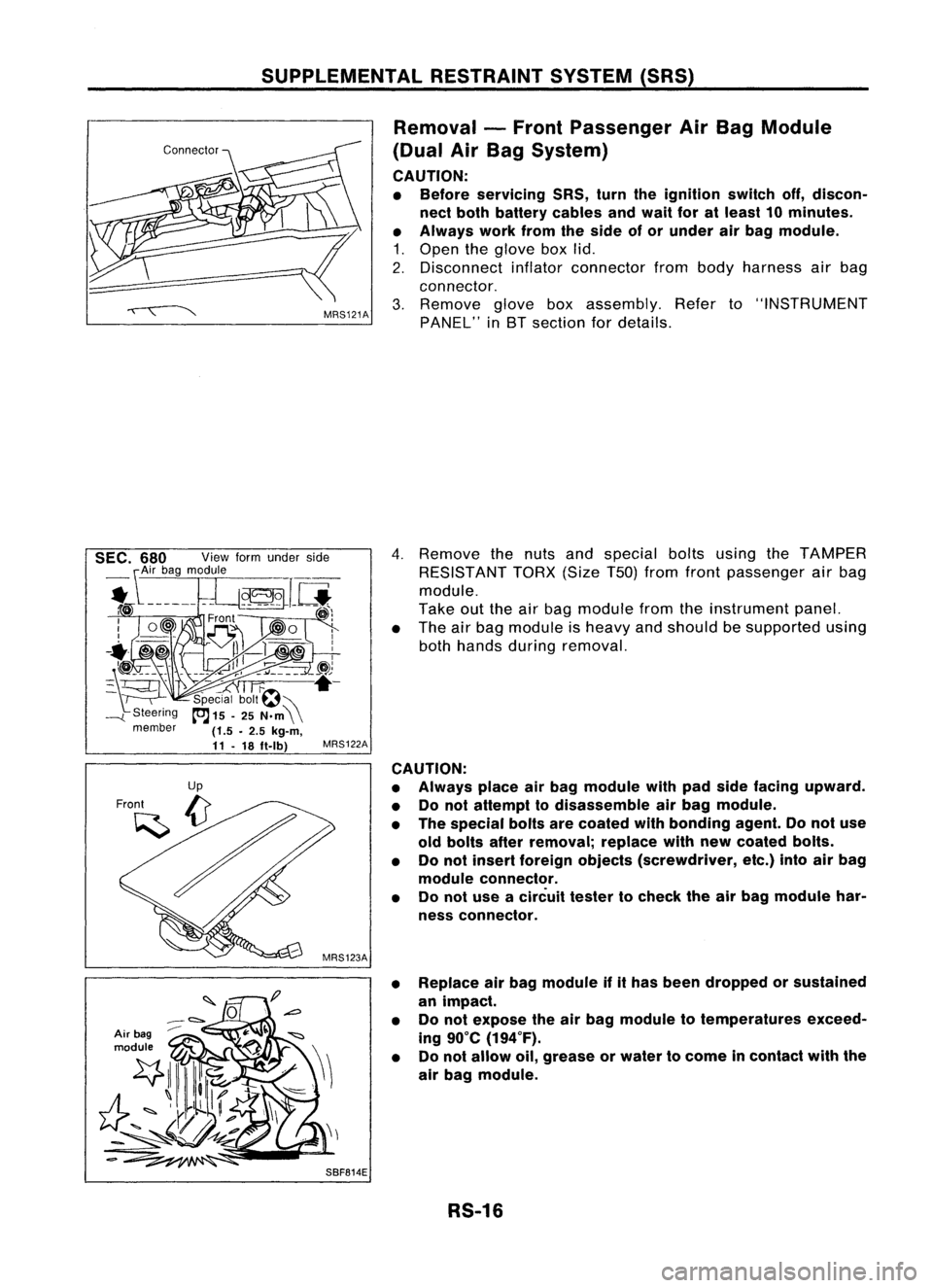
Remove thenuts andspecial boltsusing theTAMPER
RESISTANT TORX(SizeT50jfrom front passenger airbag
module.
Take outtheairbag module fromtheinstrument panel.
• The airbag module isheavy andshould besupported using
both hands during removal.
MRS122A
CAUTION:
• Always placeairbag module withpadside facing upward.
• Donot attempt todisassemble airbag module.
• The special boltsarecoated withbonding agent.Donot use
old bolts afterremoval; replacewithnewcoated bolts.
• Donot insert foreign objects (screwdriver, etc.)intoairbag
module connector.
• Donot use acircuit testertocheck theairbag module har-
ness connector.
• Replace airbag module ifithas been dropped orsustained
an impact.
• Donot expose theairbag module totemperatures exceed-
ing 90°C (194°F).
• Donot allow oil,grease orwater tocome incontact withthe
air bag module.
SBF814E RS-16
Page 1639 of 1701
SUPPLEMENTALRESTRAINTSYSTEM(SRS)
Disposal ofAir Bag Module andSeat Belt
Pre-tensioner
• Before disposing ofair bag module andseat beltpre-tensioner, orvehicles equipped withsuch
systems, deploythesystems. Ifsuch systems havealready beendeployed duetoan accident, dis-
pose ofas indicated in"DISPOSING OFAIR BAG MODULE ANDSEAT BELTPRE-TENSIONER" (RS-
24).
• When deploying theairbag module, alwaysusetheSpecial Service Tool;Deployment tool
KV99106400.
• When deploying theairbag module andseat beltpre-tensioner, standatleast 5m (16 ft)away from
the deployment component.
• Due toheat, leave airbag module unattended formore than30minutes afterdeployment. Alsoleave
seat beltpre-tensioner unattendedformore than10minutes afterdeployment.
• Besure towear gloves whenhandling adeployed airbag module andseat beltpre-tensioner.
• Never applywater toadeployed airbag module.
• Wash yourhands cleanafterfinishing- work.
• Donot dispose ofthe airbag module andseat beltpre-tensioner un-deployed.
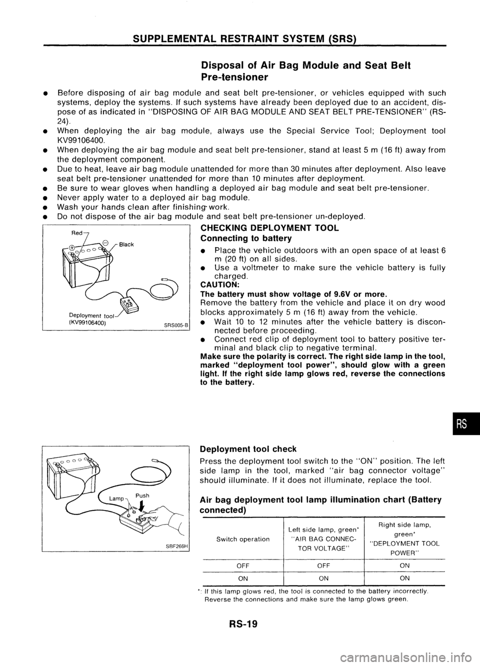
CHECKING DEPLOYMENT TOOL
Connecting tobattery
• Place thevehicle outdoors withanopen space ofat least 6
m (20
ft)
on allsides.
• Use avoltmeter tomake surethevehicle batteryisfully
charged.
CAUTION:
The battery mustshow voltage of9.6V ormore.
Remove thebattery fromthevehicle andplace iton dry wood
Deployment
tool blocksapproximately 5m (16 ft)away fromthevehicle.
(KV99106400j SRS005-B•
Wait 10to12 minutes afterthevehicle batteryisdiscon-
nected beforeproceeding.
• Connect redclip ofdeployment tooltobattery positive ter-
minal andblack cliptonegative terminal.
Make surethepolarity iscorrect. Theright sidelamp inthe tool,
marked "deployment toolpower", shouldglowwithagreen
light. Ifthe right sidelamp glows red,reverse theconnections
to the battery.
•
SBF266H Deployment
toolcheck
Press thedeployment toolswitch tothe "ON" position. Theleft
side lamp inthe tool, marked "airbagconnector voltage"
should illuminate.
If
it
does notilluminate, replacethetool.
Air bag deployment toollamp illumination chart(Battery
connected)
Leftside lamp, green' RighI
sidelamp,
Switch operation "AIR
BAGCONNEC- green'
"DEPLOYMENT TOOL
TOR VOLTAGE"
POWER"
OFF OFF ON
ON ON
ON
,. Ifthis lamp glows red,the1001 isconnecled tothe battery incorrectly.
Reverse theconnections andmake surethelamp glows green.
RS-19
Page 1642 of 1701
SBF240F
SRS006-B
SUPPLEMENTAL
RESTRAINTSYSTEM(SRS)
Disposal ofAir Bag Module andSeat Belt
Pre-tensioner (Cont'd)
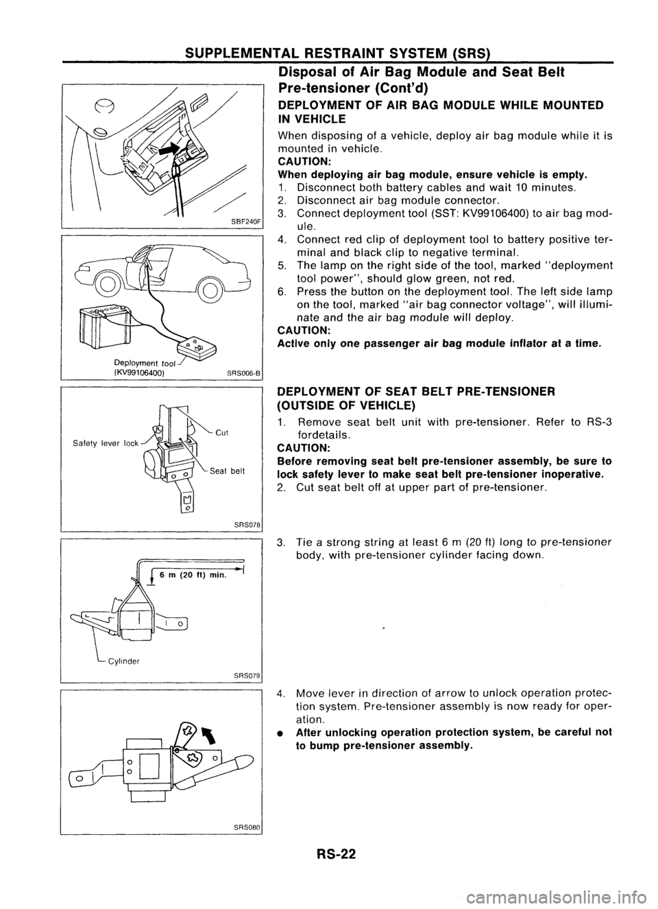
DEPLOYMENT OFAIR BAG MODULE WHILEMOUNTED
IN VEHICLE
When disposing ofavehicle, deployairbag module whileitis
mounted invehicle.
CAUTION:
When deploying airbag module, ensurevehicle isempty.
1. Disconnect bothbattery cablesandwait 10minutes.
2. Disconnect airbag module connector.
3. Connect deployment tool(SST: KV99106400) toair bag mod-
ule.
4. Connect redclip ofdeployment tooltobattery positive ter-
minal andblack cliptonegative terminal.
5. The lamp onthe right sideofthe tool, marked "deployment
tool power", shouldglowgreen, notred.
6. Press thebutton onthe deployment tool.Theleftside lamp
on the tool, marked "airbagconnector voltage",willillumi-
nate andtheairbag module willdeploy.
CAUTION:
Active onlyonepassenger airbag module inflatoratatime.
Deployment tool
(KV99106400)
Safety leverlock DEPLOYMENT
OFSEAT BELTPRE-TENSIONER
(OUTSIDE OFVEHICLE)
1. Remove seatbeltunitwith pre-tensioner. RefertoRS-3
fordetails.
CAUTION: Before removing seatbeltpre-tensioner assembly,besure to
lock safety levertomake seatbeltpre-tensioner inoperative.
2. Cut seat beltoffatupper partofpre-tensioner.
SRS078
3.Tie astrong stringatleast 6m (20
ft)
long topre-tensioner
body, withpre-tensioner cylinderfacingdown.
SRS079
4.Move leverindirection ofarrow tounlock operation protec-
tion system. Pre-tensioner assemblyisnow ready foroper-
ation.
• After unlocking operationprotection system,becareful not
to bump pre-tensioner assembly.
SRS080 RS-22
Page 1645 of 1701
TROUBLEDIAGNOSES -Supplemental RestraintSystem(SRS)
How toPerform TroubleDiagnoses forQuick
and Accurate Repair
A good understanding ofthe malfunction conditionscanmake troubleshooting fasterandmore accurate.
In general, eachcustomer feelsdifferently aboutaproblem. Itis important tofully understand the
symptoms orconditions foracustomer complaint.
INFORMATION FROMCUSTOMER
WHAT Vehiclemodel
WHEN Date,Frequencies
WHERE Roadconditions
HOW Operatingconditions, Symptoms
PRELIMINARY CHECK
Check thatthefollowing partsareingood" order.
• Battery [RefertoMA section ("GENERAL MAINTENANCE").]
• Fuse [Refer toEL section ("Fuse", "POWER SUPPLYROUTING").]
• System component-to-harness connections
DIAGNOSIS FUNCTION
The SRS self-diagnosis resultscanberead byusing "AIRBAG" warning lampand/or CONSULT.
USING WARNING LAMP
USINGCONSULT
User mode Diagnosismode
Dual airbag system
X
X X
Single airbag system
X
Seat beltpre-tensioner
The reading ofthese results isaccomplished usingoneoftwo modes -"User mode" and"Diagnosis
mode".
The User mode isexclusively preparedforthe customer (driver).Thismode warns thedriver ofasys-
tem malfunction throughtheoperation ofthe "AIR BAG" warning lamp.
The Diagnosis modeallows thetechnician tolocate andinspect themalfunctioning part.
The mode applications forthe "AIR BAG" warning lampandCONSULT areasfollows:
User mode Diagnosis
mode Displaytype
"AIR BAG" warning lamp
X
X
ON-OFF
operation
CONSULT
X
Monitoring
Seat beltpre-tensioner cannotbediagnosed byusing warning lampand/or CONSULT. Whenseatbelt
pre-tensioner isrequires servicing, visuallycheckseatbeltpre-tensioner assembly.Ifdamaged, replace
with anew one.
DIAGNOSIS MODEFORCONSULT (ForDual AirBag System)
• SELF-DIAG RESULTS
A current Self-diagnosis result(alsoindicated bythe number ofwarning lampflashes inthe Diag-
nosis mode) isdisplayed onthe CONSULT screeninreal time. Thisrefers toamalfunctioning part
requiring repairs.
RS-25
•
Page 1652 of 1701
TROUBLEDIAGNOSES -Supplemental RestraintSystem(SRS)-
Dual AirBag System
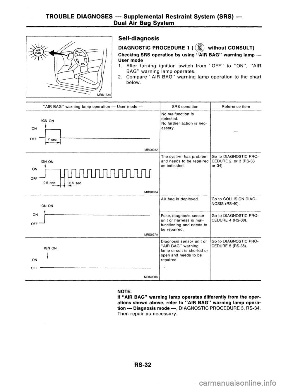
Self-diagnosis DIAGNOSTIC PROCEDURE 1(@ without CONSULT)
Checking SRSoperation byusing" AIRBAG" warning lamp-
User mode
1. After turning ignition switchfrom"OFF" to"ON", "AIR
BAG" warning lampoperates.
2. Compare "AIRBAG" warning lampoperation tothe chart
below.
"AIR BAG" warning lampoperation -User mode -
IGN ON
i
ON
J
I
OFF ~~----------------
MRS095A
SRS
condition
No malfunction is
detected. No further actionisnec-
essary. Reference
item
ON
OFF
The
system hasproblem GotoDIAGNOSTIC PRO-
and needs tobe repaired CEDURE2,or 3(RS-33
as indicated. or34).
MRS096A
lGN ON
ON •
OFF
Jr--------------------
MRS097A
IGN ON
ON
OFF --------------------
MRS098A
Air
bag isdeployed. GotoCOLLISION DIAG-
NOSIS (RS-40).
Fuse, diagnosis sensor GotoDIAGNOSTIC PRO-
unit orharness ismal- CEDURE 4(RS-38).
functioning andneeds to
be repaired.
Diagnosis sensorunitor GotoDIAGNOSTIC PRO-
"AIR BAG" warning CEDURE5(RS-38).
lamp circuit isshorted or
open andneeds tobe
repaired.
NOTE:
If "AIR BAG" warning lampoperates differently fromtheoper-
ations shown above, referto"AIR BAG" warning lampopera-
tion -Diagnosis mode-,
DIAGNOSTIC PROCEDURE3,RS-34.
Then repair asnecessary.
RS-32