Page 1653 of 1701
TROUBLEDIAGNOSES -Supplemental RestraintSystem(SRS)-
Dual AirBag System
Self-diagnosis (Cont'd)
DIAGNOSTIC PROCEDURE2
(00
withCONSULT)
Inspecting SRSmalfunctioning partsbyusing CONSULT -
Diagnosis mode
1. Turn ignition switch"OFF".
2. Connect "CONSULT" toData linkconnector.
MRS124A
AIRBAG SELF-DIAG RESULTS
NISSAN
CONSULT
START
SUB MODE
I
SRS046
I ~
SELECT SYSTEM
01
I
ENGINE
1
1 '
1-----1
I
I
I 1
MRS125A
I ~
SELECT DIAGMODE
01
I
ECUDISCRIMINATED NO.
I
'======
1 -
1 -
1========
SRS043
• SELF-DIAG RESULTS.
0
FAILURE DETECTED
CONTROL UNIT
I
ERASE
II
PRINT
I
SRS064
3.
Turn ignition switch"ON".
4. Touch "START".
5. Touch "AIRBAG".
6. Touch "SELF-DIAG RESULTS".
7. Diagnostic codesaredisplayed on"SELF-DIAG RESULTS".
RS-33
•
Page 1654 of 1701
•SELF-DIAG RESULTS.
0
FAILURE DETECTED
• NO SELF DIAGNOSTIC
FAILURE INDICATED.
TROUBLE
DIAGNOSES -Supplemental RestraintSystem(SRS)-
Dual AirBag System
Self-diagnosis (Cont'd)
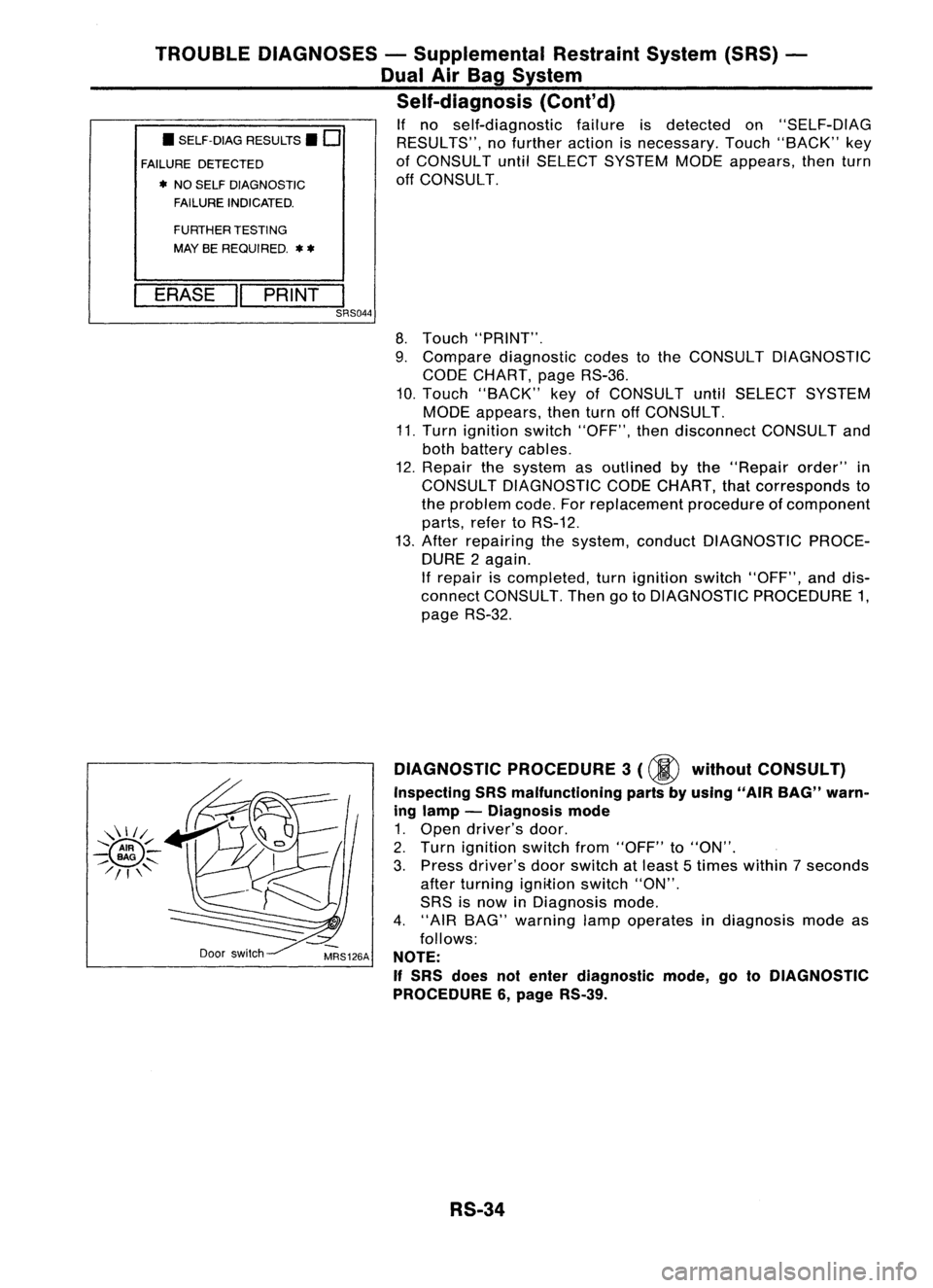
If no self-diagnostic failureisdetected on"SELF-DIAG
RESULTS", nofurther actionisnecessary. Touch"BACK" key
of CONSULT untilSELECT SYSTEM MODEappears, thenturn
off CONSULT.
FURTHER TESTING
MAY BEREQUIRED.
**
ERASE "PRINT
I
SRS044
8.Touch "PRINT".
9. Compare diagnostic codestothe CONSULT DIAGNOSTIC
CODE CHART, pageRS-36.
10. Touch "BACK" keyofCONSULT untilSELECT SYSTEM
MODE appears, thenturnoffCONSULT.
11. Turn ignition switch"OFF", thendisconnect CONSULTand
both battery cables.
12. Repair thesystem asoutlined bythe "Repair order"in
CONSULT DIAGNOSTIC CODECHART, thatcorresponds to
the problem code.Forreplacement procedureofcomponent
parts, refertoRS-12.
13. After repairing thesystem, conduct DIAGNOSTIC PROCE-
DURE 2again.
If repair iscompleted, turnignition switch"OFF", anddis-
connect CONSULT. ThengotoDIAGNOSTIC PROCEDURE 1,
page RS-32.
Door switch DIAGNOSTIC
PROCEDURE 3
(00
without CONSULT)
Inspecting SRSmalfunctioning partsbyusing "AIRBAG" warn-
ing lamp -Diagnosis mode
1. Open driver's door.
2. Turn ignition switchfrom"OFF" to"ON".
3. Press driver's doorswitch atleast 5times within 7seconds
after turning ignition switch"ON".
SRS isnow inDiagnosis mode.
4. "AIR BAG" warning lampoperates indiagnosis modeas
follows:
NOTE:
If
SRS does notenter diagnostic mode,gotoDIAGNOSTIC
PROCEDURE 6,page RS-39.
RS-34
Page 1655 of 1701
TROUBLEDIAGNOSES -Supplemental RestraintSystem(SRS)-
Dual AirBag System
Self-diagnosis (Cont'd)
No.
ON
OFF
IGN
ON
t
"AIR
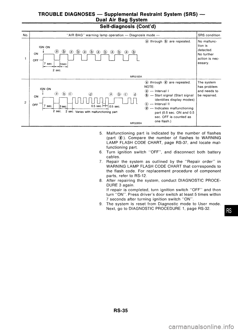
BAG" warning lampoperation -Diagnosis mode-
@
through
@
are repeated.
MRS100A
SRS
condition
No malfunc-
tion is
detected. No further
action isnec-
essary.
2 ON
OFF
IGN
ON
I
7 sec.
@)
@
(c)
3sec.
2 sec. 2sec. Varies withmalfunctioning part
MRS099A
@
through
@
are repeated.
NOTE: @ -
Interval I
@ -
Start signal (Startsignal
identifies displaymodes)
@ -
Interval II
@ -
Indicates malfunctioning
part (0.5sec. ONand 0.5
sec. OFF iscounted as
one flash.) The
system
has problem
and needs to
be repaired.
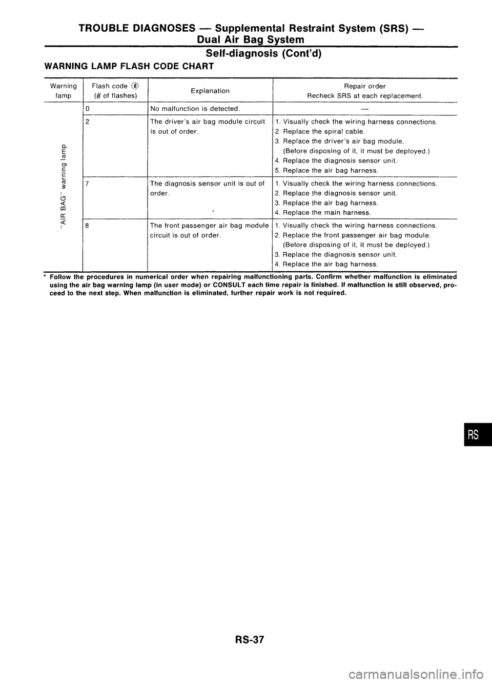
5. Malfunctioning partisindicated bythe number offlashes
(part
@).
Compare thenumber offlashes toWARNING
LAMP FLASH CODECHART, pageRS-37, andlocate mal-
functioning part.
6. Turn ignition switch"OFF", anddisconnect bothbattery
cables.
7. Repair thesystem asoutlined bythe "Repair order"in
WARNING LAMPFLASH CODECHART thatcorresponds to
the flash code. Forreplacement procedureofcomponent
parts, refertoRS-12.
8. After repairing thesystem, conduct DIAGNOSTIC PROCE-
DURE 3again.
If repair iscompleted, turnignition switch"OFF"andthen
turn "ON". Pressdriver's doorswitch atleast 5times within
7 seconds afterturning ignition switch"ON".
9. The system isreset fromDiagnostic modetoUser mode.
Next, gotoDIAGNOSTIC PROCEDURE 1,page RS-32. •
RS-35
Page 1657 of 1701
TROUBLEDIAGNOSES -Supplemental RestraintSystem(SRS)
Dual AirBag System
Self-diagnosis
(Cont'd)
WARNING LAMPFLASH CODECHART
Warning Flashcode
@
Explanation Repair
order
lamp (#offlashes)
RecheckSRSateach replacement.
0
Nomalfunction isdetected.
-
2 The
driver's airbag module circuit
1.Visually checkthewiring harness connections.
is out oforder.
2.Replace thespiral cable.
D.
3.
Replace thedriver's airbag module.
E
(Before
disposing ofit,itmust bedeployed.)
(Ij
-
4.Replace thediagnosis sensorunit.
en
c
5.Replace theairbag harness.
c
ca
7
The
diagnosis sensorunitisout of 1.Visually checkthewiring harness connections.
~
order. 2.
Replace thediagnosis sensorunit.
C)
3.Replace theairbag harness.
«
OJ
.
4.Replace themain harness .
cr:
;:(
8
The
front passenger airbag module 1.Visually checkthewiring harness connections.
circuit isout oforder. 2.Replace thefront passenger airbag module.
(Before disposing of
it,it
must bedeployed.)
3. Replace thediagnosis sensorunit.
4. Replace theairbag harness.
* Follow theprocedures innumerical orderwhen repairing malfunctioning parts.Confirm whether malfunction iseliminaled
using theairbag warning lamp(inuser mode) orCONSULT eachtimerepair isfinished. Ifmalfunction isstill observed, pro-
ceed tothe next step. When malfunction iseliminated, furtherrepairworkisnol required.
RS-37
•
Page 1658 of 1701
TROUBLEDIAGNOSES -Supplemental RestraintSystem(SRS)-
Dual AirBag System
Trouble Diagnoses forAir Bag Warning Lamp
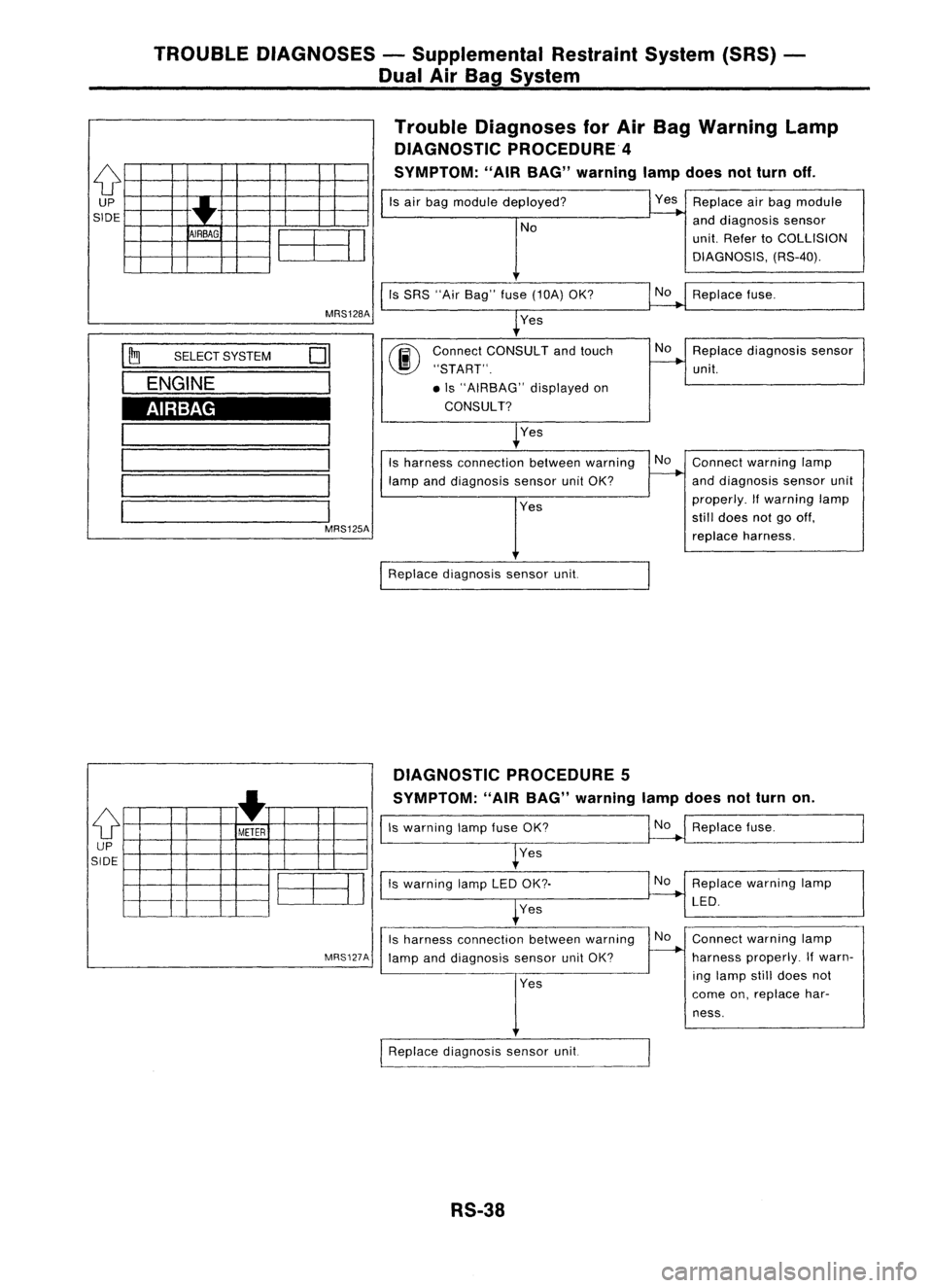
DIAGNOSTIC PROCEDURE 4
SYMPTOM: "AIRBAG" warning lampdoesnotturn off.
{f
UP
SIDE
•
T
AIRBAG
EE3J
Is
air bag module deployed?
No
Is SRS "AirBag" fuse(10A) OK?
Yes Replace
airbag module
and diagnosis sensor
unit. Refer toCOLLISION
DIAGNOSIS, (RS-40).
Replace fuse.
I ~
SELECT SYSTEM
01
I
ENGINE
I
AIRBAG
MRS125A
00
Connect
CONSULT andtouch No
Replace diagnosis sensor
"START".
----....
unit.
• Is "AIRBAG" displayedon
CONSULT?
~Yes
Is harness connection betweenwarning No
Connect warning lamp
lamp anddiagnosis sensorunitOK?
~
anddiagnosis sensorunit
Yes properly.
Ifwarning lamp
still does notgooff,
replace harness.
[RePlace diagnosissensorunit.
DIAGNOSTIC PROCEDURE 5
SYMPTOM: "AIRBAG" warning lampdoesnotturn on.
{f
+
METER
UP
SIDE
EE3J
MRS127A
Is
warning lampfuseOK?
Yes
Is warning lampLEDOK?
Yes
Is harness connection betweenwarning
lamp anddiagnosis sensorunitOK?
Yes
I
Replace diagnosis sensorunit.
RS-38
No
Replace fuse.
Replace warning lamp
LED.
Connect warning lamp
harness properly. Ifwarn-
ing lamp stilldoes not
come on,replace har-
ness.
Page 1663 of 1701
TROUBLEDIAGNOSES -Supplemental RestraintSystem(SRS)-
Single AirBag System
Self-diagnosis
DIAGNOSTIC PROCEDURE 7
(@
without CONSULT)
Checking SRSoperation byusing "AIRBAG" warning lamp-
User mode
1. After turning ignition switchfrom"OFF" to"ON", "AIR
BAG" warning lampoperates.
2. Compare "AIRBAG" warning lampoperation tothe chart
below.
Note: CONSULT cannotbeused fortrouble diagnoses.
"AIR BAG" warning lampoperation -User mode
1. Normal
IGNON
ON
!--
OFF J Approx.I _
I}
sec...
I
2. Abnormal -Ifthe warning lampshows asfollows, checktheSRS immediately.
e Blinking
e Warning lampdoes notilluminate atall.
ON
OFF
ON
OFF o.5~sec.
IGN ON
,----,
I I
I I
I
I
•
ecootiooo::JOO_IG_N_O_N _
OFF MRS106
RS-43
Page 1664 of 1701
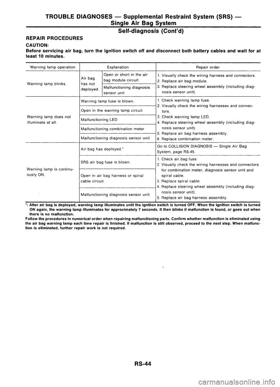
TROUBLEDIAGNOSES -Supplemental RestraintSystem(SRS)
Single AirBag System
Self-diagnosis (Cont'd)
REPAIR PROCEDURES
CAUTION:
Before servicing airbag, turntheignition switchoffand disconnect bothbattery cablesandwail forat
least 10minutes.
Warning lampoperation Explanation
Repairorder
Open orshort inthe air
1.Visually checkthewiring harness andconnectors.
Air bag
bagmodule circuit.
2.Replace airbag module.
Warning lampblinks. hasnot
3.Replace steering wheelassembly (including diag-
deployed. Malfunctioning
diagnosis
sensor unit nos
issensor unit).
Warning lampfuseisblown. 1.
Check warning lampfuse.
2. Visually checkthewiring harnesses andconnec-
Open inthe warning lampcircuit
tors.
Warning lampdoes not
Malfunctioning LED 3.
Check warning lampLED.
illuminate atall. 4.Replace steering wheelassembly (including diag-
Malfunctioning combinationmeter nos
issensor unit).
5. Replace airbag harness assembly.
Malfunctioning diagnosissensorunit
6.Replace combination meter.
Air bag hasdeployed: Go
toCOLLISION DIAGNOSIS -Single AirBag
System, pageRS-45.
1. Check airbag fuse.
SRS airbag fuse isblown.
2.
Visually checkthewiring harnesses andconnectors
Warning lampiscontinu-
forcombination meter,diagnosis sensorunitand
ously ON.
Openinair bag harness orspiral
spiralcable.
cable circuit 3.
Replace spiralcable.
4. Replace steeringwheelassembly (including diag-
Malfunctioning diagnosissensorunit nosis
sensor unit).
5. Replace airbag harness assembly.
*;
After airbag isdeployed, warninglampilluminates untiltheignition switchisturned OFF.When theIgnition switchisturned
ON again, Ihewarning lampilluminates forapproximately 7seconds. Itthen blinks ifmalfunction isfound, orgoes outwhen
there isno malfunction.
Follow theprocedures innumerical orderwhenrepairing malfunctioning parts.Confirm whether malfunction iseliminated using
the airbag warning lampeachtimerepair isfinished. Ifmalfunction isstill observed, proceedtothe next step. When malfunc-
tion iseliminated, furtherrepairworkisnot required.
RS-44
Page 1676 of 1701
STEERINGWHEELANDSTEERING COLUMN
Removal andInstallation (Cont'd)
• Align spiral cablecorrectly wheninstalling steeringwheel.
a. Set thefront wheels inthe straight-ahead position.
b. Make surethatthespiral cableisin the neutral position.
\ Theneutral position isdetected byturning left2.5revolu-
~ tionsfromtheright endposition. Alignthetwo marks (~').
CAUTION:
The spiral cablemaysnap duetosteering operation ifthe cable
is installed inan improper position.
Also, withthesteering linkagedisconnected, thecable may
snap byturning thesteering wheelbeyond thelimited number
of turns. (Thespiral cablecanbeturned upto2.5 turns fromthe
neutral position toboth theright andleft.)
MBF487BA
•Remove steering wheelwithTool.
Without AirBag
1. Remove hornpad.
Insert acrosshead screwdriver intohole onlower sideof
spoke andremove clamp.
Lift
horn padoffbyhand.
Three spoke type
Cross headscrewdriver SST502C
SST495CA ST-10
Page:
< prev 1-8 9-16 17-24