1995 JEEP YJ wheel bolts
[x] Cancel search: wheel boltsPage 1531 of 2158
STEERING COLUMN GENERAL SERVICEÐXJ
INDEX
page
Airbag System........................... 47
AIRBAG SYSTEM
WARNING: THE MECHANICAL AIRBAG SYSTEM IS
A SENSITIVE, COMPLEX MECHANICAL UNIT. BE-
FORE ATTEMPTING TO REMOVE OR INSTALL THE
AIRBAG SYSTEM OR RELATED STEERING WHEEL
AND STEERING COLUMN COMPONENTS YOU
MUST FIRST DISARM THE AIRBAG FIRING MECHA-
NISM. FAILURE TO DO SO COULD RESULT IN AC-
CIDENTAL DEPLOYMENT AND POSSIBLE INJURY.
WARNING: THE AIRBAG MODULE INFLATOR/SEN-
SOR ASSEMBLY CONTAINS SODIUM AZIDE AND
POTASSIUM NITRATE. THESE MATERIALS ARE
POISONOUS AND EXTREMELY FLAMMABLE. CON-
TACT WITH ACID, WATER OR HEAVY METALS MAY
PRODUCE HARMFUL AND IRRITATING GASES (SO-
DIUM HYDROXIDE IS FORMED IN THE PRESENCE
OF MOISTURE) OR COMBUSTIBLE COMPOUNDS.
DO NOT ATTEMPT TO DISMANTLE THE MODULE
OR TAMPER WITH ITS ARMING LEVER. DO NOT
PUNCTURE, INCINERATE, OR BRING INTO CON-
TACT WITH ELECTRICITY. DO NOT STORE AT TEM-
PERATURES EXCEEDING 200ÉF.WARNING: REPLACE AIRBAG SYSTEM COMPO-
NENTS WITH PARTS SPECIFIED IN THE CHRYSLER
MOPAR PARTS CATALOG ONLY. IT IS OF PARTICU-
LAR IMPORTANCE THAT ANY COMPONENTS USED
IN THIS MECHANICALLY-FIRED AIRBAG SYSTEM
NOT BE MIXED WITH COMPONENTS FROM AN
ELECTRICALLY-FIRED AIRBAG SYSTEM. SUBSTI-
TUTE PARTS MAY APPEAR THE SAME, BUT INTER-
NAL DIFFERENCES MAY RESULT IN INFERIOR
OCCUPANT PROTECTION.
WARNING: THE FASTENERS, SCREWS, AND
BOLTS, ORIGINALLY USED FOR THE AIRBAG COM-
PONENTS, HAVE SPECIAL COATINGS AND ARE
SPECIFICALLY DESIGNED FOR THE AIRBAG SYS-
TEM. THEY MUST NEVER BE REPLACED WITH ANY
SUBSTITUTES. ANYTIME A NEW FASTENER IS
NEEDED, REPLACE WITH THE CORRECT FASTEN-
ERS PROVIDED IN THE SERVICE PACKAGE OR
SPECIFIED IN THE CHRYSLER MOPAR PARTS CAT-
ALOG.
JSTEERING 19 - 47
Page 1532 of 2158
GENERAL INFORMATION
The airbag system is a standard equipment safety
device on XJ (Cherokee) models. It is designed to pro-
tect the driver from serious injury, caused by a fron-
tal impact of the vehicle. If the airbag module
assembly is defective and non-deployed, refer to
Chrysler Corporation current return list for proper
handling procedures.
ARMING/DISARMING MECHANISM
BEFORE SERVICING A COLUMN EQUIPPED
WITH AIR BAG, REFER TO GROUP 8M, ELEC-
TRICAL FOR PROPER AND SAFE PROCE-
DURES.
The steering wheel hub incorporates an airbag
Arming/Disarming mechanism and a specially de-
signed nut-blocker. The nut-blocker serves as a safety
to prevent removal of the airbag module until the
unit has been disarmed. A removable plastic cover
plug on the top, outer hub of the steering wheel al-
lows access to the arming screw.
When the airbag module is disarmed, the arming
screw extends upward from the steering wheel hub.
This will prevent installation of the plastic cover
plug. Also, the nut-blocker is retracted to allow ac-
cess to the two upper airbag module mounting nuts.
When the airbag module is armed, the plastic cover
plug will install flush with the outer surface of the
steering wheel hub. In addition, the nut-blocker will
prevent access to the two upper airbag module
mounting nuts.THE FASTENERS, SCREWS, AND BOLTS, ORIG-
INALLY USED FOR THE AIR BAG COMPONENTS,
HAVE SPECIAL COATINGS. THIS HARDWARE IS
SPECIFICALLY DESIGNED FOR THE AIR BAG
SYSTEM. THEY MUST NEVER BE REPLACED
WITH ANY SUBSTITUTES. REPLACE WITH THE
CORRECT FASTENERS PROVIDED IN THE SER-
VICE PACKAGE OR FASTENERS IN THE PARTS
BOOK.
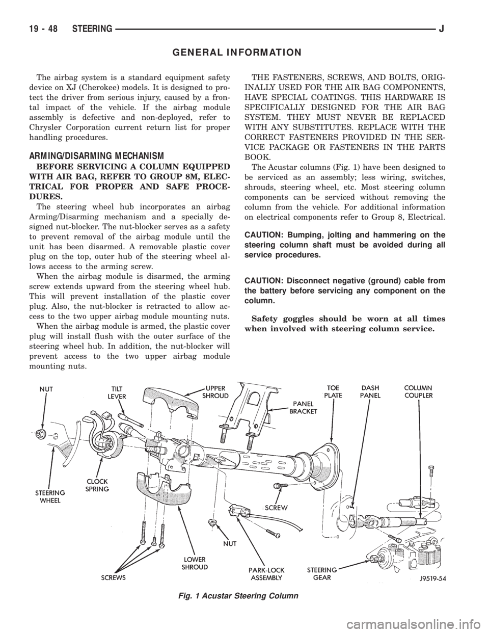
The Acustar columns (Fig. 1) have been designed to
be serviced as an assembly; less wiring, switches,
shrouds, steering wheel, etc. Most steering column
components can be serviced without removing the
column from the vehicle. For additional information
on electrical components refer to Group 8, Electrical.
CAUTION: Bumping, jolting and hammering on the
steering column shaft must be avoided during all
service procedures.
CAUTION: Disconnect negative (ground) cable from
the battery before servicing any component on the
column.
Safety goggles should be worn at all times
when involved with steering column service.
Fig. 1 Acustar Steering Column
19 - 48 STEERINGJ
Page 1543 of 2158
(1) Make sure the front wheels are in thestraight
aheadposition.
(2) Disconnect the negative (ground) cable from the
battery.
(3) Remove steering wheel from column, refer to
Steering Wheel-Removal.
(4) Column shift vehicles, disconnect the shift ca-
ble grommet by prying it from the shift lever.
(5) Disconnect the column shaft to steering gear
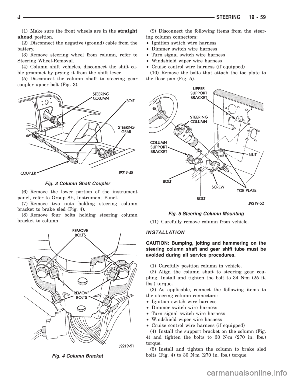
coupler upper bolt (Fig. 3).
(6) Remove the lower portion of the instrument
panel, refer to Group 8E, Instrument Panel.
(7) Remove two nuts holding steering column
bracket to brake sled (Fig. 4).
(8) Remove four bolts holding steering column
bracket to column.(9) Disconnect the following items from the steer-
ing column connectors:
²Ignition switch wire harness
²Dimmer switch wire harness
²Turn signal switch wire harness
²Windshield wiper wire harness
²Cruise control wire harness (if equipped)
(10) Remove the bolts that attach the toe plate to
the floor pan (Fig. 5).
(11) Carefully remove column from vehicle.
INSTALLATION
CAUTION: Bumping, jolting and hammering on the
steering column shaft and gear shift tube must be
avoided during all service procedures.
(1) Carefully position column in vehicle.
(2) Align the column shaft to steering gear cou-
pling. Install and tighten the bolt to 34 Nzm (25 ft.
lbs.) torque.
(3) As applicable, connect the following items to
the steering column connectors:
²Ignition switch wire harness
²Dimmer switch wire harness
²Turn signal switch wire harness
²Windshield wiper wire harness
²Cruise control wire harness (if equipped)
(4) Install the support bracket on the column (Fig.
4) and tighten the bolts to 30 Nzm (270 in. lbs.)
torque.
(5) Install and tighten the column to brake sled
bolts (Fig. 4) to 30 Nzm (270 in. lbs.) torque.
Fig. 3 Column Shaft Coupler
Fig. 4 Column Bracket
Fig. 5 Steering Column Mounting
JSTEERING 19 - 59
Page 1544 of 2158
(6) Column shift vehicles, install the shift cable
grommet on the shift lever.
(7) Install and tighten the toe plate to floor pan
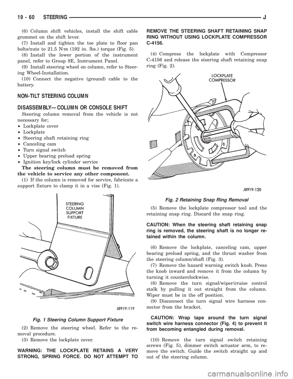
bolts/nuts to 21.5 Nzm (192 in. lbs.) torque (Fig. 5).
(8) Install the lower portion of the instrument
panel, refer to Group 8E, Instrument Panel.
(9) Install steering wheel on column, refer to Steer-
ing Wheel-Installation.
(10) Connect the negative (ground) cable to the
battery.
NON-TILT STEERING COLUMN
DISASSEMBLYÐCOLUMN OR CONSOLE SHIFT
Steering column removal from the vehicle is not
necessary for;
²Lockplate cover
²Lockplate
²Steering shaft retaining ring
²Canceling cam
²Turn signal switch
²Upper bearing preload spring
²Ignition key/lock cylinder service
The steering column must be removed from
the vehicle to service any other component.
(1) If the column is removed for service, fabricate a
support fixture to clamp it in a vise (Fig. 1).
(2) Remove the steering wheel. Refer to the re-
moval procedure.
(3) Remove the lockplate cover.
WARNING: THE LOCKPLATE RETAINS A VERY
STRONG, SPRING FORCE. DO NOT ATTEMPT TOREMOVE THE STEERING SHAFT RETAINING SNAP
RING WITHOUT USING LOCKPLATE COMPRESSOR
C-4156.
(4) Compress the lockplate with Compressor
C-4156 and release the steering shaft retaining snap
ring (Fig. 2).
(5) Remove the lockplate compressor tool and the
retaining snap ring. Discard the snap ring.
CAUTION: When the steering shaft retaining snap
ring is removed, the steering shaft is no longer re-
tained within the column.
(6) Remove the lockplate, canceling cam, upper
bearing preload spring, and the thrust washer from
the steering column/shaft (Fig. 3).
(7) Remove the hazard warning switch knob. Press
the knob inward and remove it from the column by
turning it counterclockwise.
(8) Remove the turn signal/wiper/cruise control
stalk by pulling it out straight from the column.
Wiper must be in the off position.
(9) Disconnect the turn signal wire harness con-
nector from the bracket.
CAUTION: Wrap tape around the turn signal
switch wire harness connector (Fig. 4) to prevent it
from becoming entangled during removal.
(10) Remove the turn signal switch retaining
screws (Fig. 5), dimmer switch actuator arm, to re-
move the switch. Guide the switch straight up and
out of the steering column.
Fig. 1 Steering Column Support Fixture
Fig. 2 Retaining Snap Ring Removal
19 - 60 STEERINGJ
Page 1567 of 2158
(21) Remove clutch release bearing, release fork
and retainer clip.
(22) Remove clutch housing from transmission.
TRANSMISSION INSTALLATION
(1) Install clutch housing on transmission. Tighten
housing bolts to 37 Nzm (27 ft. lbs.) torque.
(2) Lubricate contact surfaces of release fork pivot
ball stud and release fork with high temp grease.
Then install release bearing, fork and retainer clip.
(3) Mount transmission on transmission jack.
(4) Lightly lubricate pilot bearing and transmis-
sion input shaft splines with Mopar high temp
grease.
(5) Align transmission input shaft, release bearing,
and clutch disc splines. Then slide transmission into
place.
(6) Install and tighten clutch housing-to-engine
bolts to 38 Nzm (28 ft. lbs.) torque.Be sure the
housing is properly seated on engine block be-
fore tightening bolts.
(7) Lower transmission approximately 7-8 cm (3
in.) for access to shift tower. Be sure transmission is
in first or third gear.
(8) Reach up and around transmission and insert
shift lever in shift tower. Press lever retainer down-
ward and turn it clockwise to lock it in place. Then
install lever dust boot on shift tower.
(9) Install slave cylinder in clutch housing.
(10) Align and install transfer case on and trans-
mission. Tighten transfer case-to-transmission nuts
to 35 Nzm (26 ft. lbs.) torque.
(11) Connect transfer case vent hose and shift link-
age. Check and adjust linkage if necessary.
(12) Connect transfer case vent hose.
(13) Secure wire harnesses in clips/tie straps on
transmission and transfer case.
(14) Connect backup light switch wires.
(15) Connect vehicle speed sensor wires.
(16) Install and connect crankshaft position sensor.
(17) Install rear crossmember (Fig. 5). On XJ,
tighten crossmember-to-frame bolts to 41 Nzm (31 ft.
lbs.) torque. Then tighten transmission-to-rear sup-
port bolts/nuts to 45 Nzm (33 ft. lbs.) torque. On YJ,
tighten bolts/nuts to indicated torque (Fig. 5).
(18) Remove jack stand.
(19) Align and install front/rear propeller shafts.
Tighten shaft U-joint clamp bolts to 19 Nzm (170 in.
lbs.) torque.
(20) Install skid plate, if equipped. Tighten bolts to
42 Nzm (31 ft. lbs.) torque. Tighten stud nuts to 17
Nzm (150 in. lbs.) torque.
(21) Top off transmission and transfer case lubri-
cant levels.
(22) Lower vehicle.
TRANSMISSION DISASSEMBLY AND OVERHAUL
ADAPTER HOUSING AND FRONT BEARING
RETAINER REMOVAL
(1) Drain transmission lubricant.
(2) Remove release bearing and lever.
(3) Remove clutch housing bolts and remove hous-
ing.
(4) On 2-wheel drive models, remove vehicle speed
sensor, speedometer adapter and speedometer driven
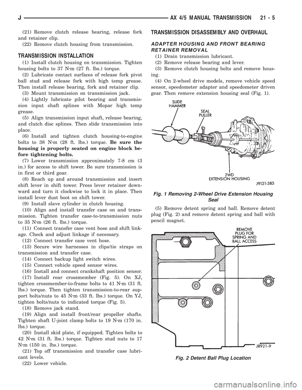
gear. Then remove extension housing seal (Fig. 1).
(5) Remove detent spring and ball. Remove detent
plug (Fig. 2) and remove detent spring and ball with
pencil magnet.
Fig. 1 Removing 2-Wheel Drive Extension Housing
Seal
Fig. 2 Detent Ball Plug Location
JAX 4/5 MANUAL TRANSMISSION 21 - 5
Page 1594 of 2158
(10) Install lock ball and spring in housing. Then
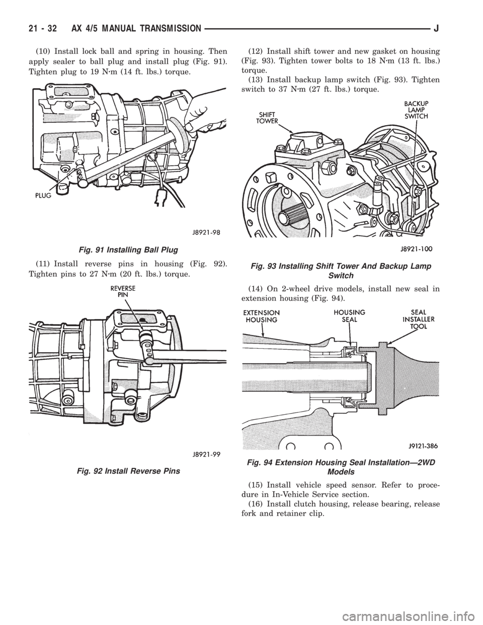
apply sealer to ball plug and install plug (Fig. 91).
Tighten plug to 19 Nzm (14 ft. lbs.) torque.
(11) Install reverse pins in housing (Fig. 92).
Tighten pins to 27 Nzm (20 ft. lbs.) torque.(12) Install shift tower and new gasket on housing
(Fig. 93). Tighten tower bolts to 18 Nzm (13 ft. lbs.)
torque.
(13) Install backup lamp switch (Fig. 93). Tighten
switch to 37 Nzm (27 ft. lbs.) torque.
(14) On 2-wheel drive models, install new seal in
extension housing (Fig. 94).
(15) Install vehicle speed sensor. Refer to proce-
dure in In-Vehicle Service section.
(16) Install clutch housing, release bearing, release
fork and retainer clip.
Fig. 91 Installing Ball Plug
Fig. 92 Install Reverse Pins
Fig. 93 Installing Shift Tower And Backup Lamp
Switch
Fig. 94 Extension Housing Seal InstallationÐ2WD
Models
21 - 32 AX 4/5 MANUAL TRANSMISSIONJ
Page 1921 of 2158
EXTERIOR COMPONENTS
INDEX
page page
Air Exhaust GrilleÐXJ...................... 25
Battery TrayÐXJ.......................... 14
Body Side Molding/CladdingÐXJ.............. 20
Body Stripes/DecalsÐXJ.................... 21
Brush GuardÐXJ.......................... 3
Cowl Grille and ScreenÐXJ................. 12
Cowl Weatherstrip Seal/Crossmember Air
DeflectorÐXJ........................... 11
Dash Panel Insulator PanelÐXJ.............. 12
Drip Rail MoldingÐXJ...................... 25
Exterior NameplatesÐXJ................... 26
External MirrorsÐXJ....................... 27
Front FenderÐXJ......................... 14
Fuel Filler Door BumpersÐXJ................ 27Fuel Filler Nozzle/TubeÐXJ................. 26
Grille and Grille Opening Panel (GOP)ÐXJ....... 3
Hood AdjustmentÐXJ...................... 10
Hood Hinge ReplacementÐXJ............... 10
Hood Latch ReplacementÐXJ................ 11
Hood Latch Striker ReplacementÐXJ.......... 11
HoodÐXJ................................ 7
Latch Release Cable ReplacementÐXJ......... 11
Luggage RackÐXJ........................ 28
Quarter Window AppliqueÐXJ................ 25
Radiator Support CrossmemberÐXJ............ 6
Rear Wheelhouse Flares and LinersÐXJ........ 19
Safety Latch Striker ReplacementÐXJ.......... 11
BRUSH GUARDÐXJ
REMOVAL
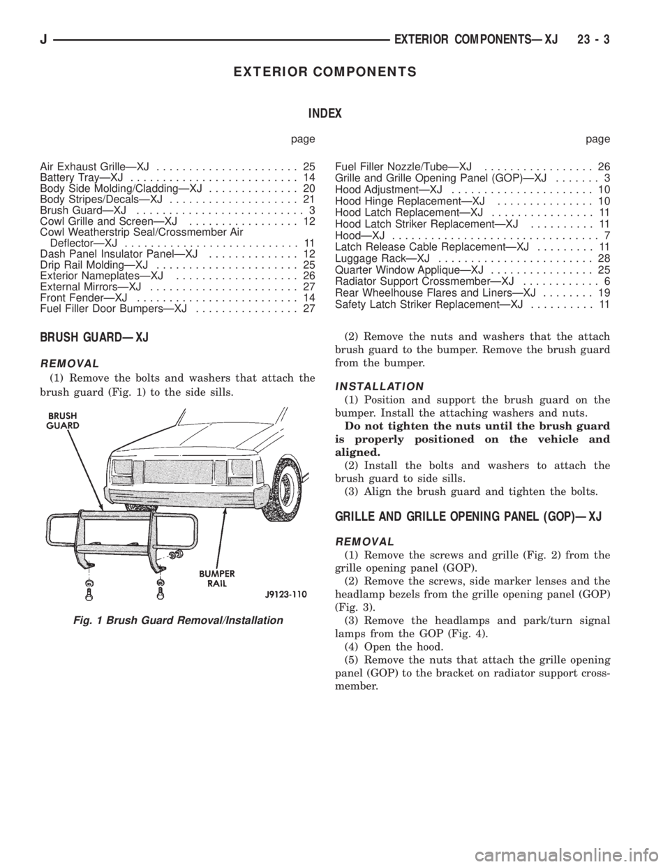
(1) Remove the bolts and washers that attach the
brush guard (Fig. 1) to the side sills.(2) Remove the nuts and washers that the attach
brush guard to the bumper. Remove the brush guard
from the bumper.INSTALLATION
(1) Position and support the brush guard on the
bumper. Install the attaching washers and nuts.
Do not tighten the nuts until the brush guard
is properly positioned on the vehicle and
aligned.
(2) Install the bolts and washers to attach the
brush guard to side sills.
(3) Align the brush guard and tighten the bolts.
GRILLE AND GRILLE OPENING PANEL (GOP)ÐXJ
REMOVAL
(1) Remove the screws and grille (Fig. 2) from the
grille opening panel (GOP).
(2) Remove the screws, side marker lenses and the
headlamp bezels from the grille opening panel (GOP)
(Fig. 3).
(3) Remove the headlamps and park/turn signal
lamps from the GOP (Fig. 4).
(4) Open the hood.
(5) Remove the nuts that attach the grille opening
panel (GOP) to the bracket on radiator support cross-
member.
Fig. 1 Brush Guard Removal/Installation
JEXTERIOR COMPONENTSÐXJ 23 - 3
Page 2001 of 2158
INSTALLATION
(1) Position the replacement cover on the cushion.
(2) Compress the cover and attach the retaining
clips to the front and rear wire retainers.
(3) Install the serrated retainers at the ends of the
cover.
(4) Install the seat cushion in the vehicle. If neces-
sary, refer to the installation procedure.
REAR SEATBACKÐXJ
REMOVAL
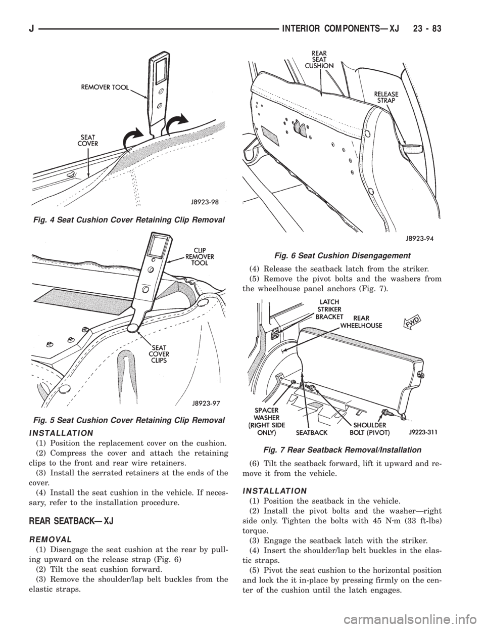
(1) Disengage the seat cushion at the rear by pull-
ing upward on the release strap (Fig. 6)
(2) Tilt the seat cushion forward.
(3) Remove the shoulder/lap belt buckles from the
elastic straps.(4) Release the seatback latch from the striker.
(5) Remove the pivot bolts and the washers from
the wheelhouse panel anchors (Fig. 7).
(6) Tilt the seatback forward, lift it upward and re-
move it from the vehicle.
INSTALLATION
(1) Position the seatback in the vehicle.
(2) Install the pivot bolts and the washerÐright
side only. Tighten the bolts with 45 Nzm (33 ft-lbs)
torque.
(3) Engage the seatback latch with the striker.
(4) Insert the shoulder/lap belt buckles in the elas-
tic straps.
(5) Pivot the seat cushion to the horizontal position
and lock the it in-place by pressing firmly on the cen-
ter of the cushion until the latch engages.
Fig. 4 Seat Cushion Cover Retaining Clip Removal
Fig. 5 Seat Cushion Cover Retaining Clip Removal
Fig. 6 Seat Cushion Disengagement
Fig. 7 Rear Seatback Removal/Installation
JINTERIOR COMPONENTSÐXJ 23 - 83