1995 JEEP YJ wheel bolts
[x] Cancel search: wheel boltsPage 238 of 2158
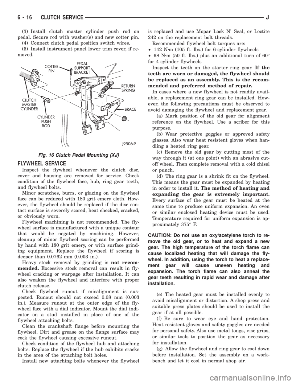
(3) Install clutch master cylinder push rod on
pedal. Secure rod with washer(s) and new cotter pin.
(4) Connect clutch pedal position switch wires.
(5) Install instrument panel lower trim cover, if re-
moved.
FLYWHEEL SERVICE
Inspect the flywheel whenever the clutch disc,
cover and housing are removed for service. Check
condition of the flywheel face, hub, ring gear teeth,
and flywheel bolts.
Minor scratches, burrs, or glazing on the flywheel
face can be reduced with 180 grit emery cloth. How-
ever, the flywheel should be replaced if the disc con-
tact surface is severely scored, heat checked, cracked,
or obviously worn.
Flywheel machining is not recommended. The fly-
wheel surface is manufactured with a unique contour
that would be negated by machining. However,
cleanup of minor flywheel scoring can be performed
by hand with 180 grit emery, or with surface grind-
ing equipment. Replace the flywheel if scoring is
deeper than 0.0762 mm (0.003 in.).
Heavy stock removal by grinding isnot recom-
mended.Excessive stock removal can result in fly-
wheel cracking or warpage after installation. It can
also weaken the flywheel and interfere with proper
clutch release.
Check flywheel runout if misalignment is sus-
pected. Runout should not exceed 0.08 mm (0.003
in.). Measure runout at the outer edge of the fly-
wheel face with a dial indicator. Mount the dial indi-
cator on a stud installed in place of one of the
flywheel attaching bolts.
Clean the crankshaft flange before mounting the
flywheel. Dirt and grease on the flange surface may
cock the flywheel causing excessive runout.
Check condition of the flywheel hub and attaching
bolts. Replace the flywheel if the hub exhibits cracks
in the area of the attaching bolt holes.
Install new attaching bolts whenever the flywheelis replaced and use Mopar Lock N' Seal, or Loctite
242 on the replacement bolt threads.
Recommended flywheel bolt torques are:
²142 Nzm (105 ft. lbs.) for 6-cylinder flywheels
²68 Nzm (50 ft. lbs.) plus an additional turn of 60É
for 4-cylinder flywheels
Inspect the teeth on the starter ring gear.If the
teeth are worn or damaged, the flywheel should
be replaced as an assembly. This is the recom-
mended and preferred method of repair.
In cases where a new flywheel is not readily avail-
able, a replacement ring gear can be installed. How-
ever, the following precautions must be observed to
avoid damaging the flywheel and replacement gear.
(a) Mark position of the old gear for alignment
reference on the flywheel. Use a scriber for this
purpose.
(b) Wear protective goggles or approved safety
glasses. Also wear heat resistent gloves when han-
dling a heated ring gear.
(c) Remove the old gear by cutting most of the
way through it (at one point) with an abrasive cut-
off wheel. Then complete removal with a cold chisel
or punch.
(d) The ring gear is a shrink fit on the flywheel.
This means the gear must be expanded by heating
in order to install it.The method of heating and
expanding the gear is extremely important.
Every surface of the gear must be heated at the
same time to produce uniform expansion. An oven
or similar enclosed heating device must be used.
Temperature required for uniform expansion is ap-
proximately 375É F.
CAUTION: Do not use an oxy/acetylene torch to re-
move the old gear, or to heat and expand a new
gear. The high temperature of the torch flame can
cause localized heating that will damage the fly-
wheel. In addition, using the torch to heat a replace-
ment gear will cause uneven heating and
expansion. The torch flame can also anneal the
gear teeth resulting in rapid wear and damage after
installation.
(e) The heated gear must be installed evenly to
avoid misalignment or distortion. A shop press and
suitable press plates should be used to install the
gear if at all possible.
(f) Be sure to wear eye and hand protection.
Heat resistent gloves and safety goggles are needed
for personal safety. Also use metal tongs, vise grips,
or similar tools to position the gear as necessary
for installation.
(g) Allow the flywheel and ring gear to cool down
before installation. Set the assembly on a work-
bench and let it cool in normal shop air.
Fig. 16 Clutch Pedal Mounting (XJ)
6 - 16 CLUTCH SERVICEJ
Page 312 of 2158

CAUTION: Be certain that battery cables are con-
nected to the correct battery terminals. Reverse po-
larity can damage electrical components.
(12) Place oiled felt washer on battery positive ter-
minal post.
(13) Install and tighten battery positive cable ter-
minal clamp. Then install and tighten negative cableterminal clamp. Both cable clamp bolts require
torque of 8.5 Nzm (75 in. lbs.).
(14) Apply a thin coating of petroleum jelly or
chassis grease to cable terminals and battery posts.
STARTER AND STARTER RELAY
GENERAL INFORMATION
This section covers starter and starter relay service
procedures only. For diagnostic procedures, refer to
Group 8A - Battery/Starting/Charging Systems Diag-
nostics. Service procedures for other starting system
components can be found as follows:
²battery - see Battery, in this group
²ignition switch - refer to Group 8D - Ignition Sys-
tems
²park/neutral position switch (automatic transmis-
sion) - refer to Group 21 - Transmission and Transfer
Case
²wiring harness and connectors - refer to Group 8W
- Wiring Diagrams.
STARTER
The starter motor incorporates several features to
create a reliable, efficient, compact and lightweight
unit. A planetary gear system (intermediate trans-
mission) is used between the electric motor and pin-
ion gear. This feature makes it possible to reduce the
dimensions of the starter. At the same time, it allows
higher armature rotational speed and delivers in-
creased torque through the pinion gear to the fly-
wheel or drive plate ring gear.
The use of a permanent magnet field also reduces
starter size and weight. This field consists of six
high-strength permanent magnets. The magnets are
aligned according to their polarity and are perma-
nently fixed in the starter field frame.
The starter motors for all engines are activated by
a solenoid mounted to the overrunning clutch hous-
ing. However, the starter motor/solenoid are serviced
only as a complete assembly. If either component
fails, the entire assembly must be replaced.
This unit is highly sensitive to hammering, shocks
and external pressure.
CAUTION: The starter motor MUST NOT BE
CLAMPED in a vise by the starter field frame. Doing
so may damage the magnets. It may be clamped by
the mounting flange ONLY.CAUTION: Do not connect starter motor incorrectly
when tests are being performed. The permanent
magnets may be damaged and rendered unservice-
able.
STARTER RELAY
The starter relay is an International Standards Or-
ganization (ISO) type relay, and is located in the
Power Distribution Center (PDC). Refer to underside
of PDC cover for relay location.
STARTER REMOVE/INSTALLÐ2.5L
XJ MODELS
(1) Disconnect battery negative cable.
(2) Remove exhaust clamp from bracket (Fig. 11).
(3) Remove nut and bolt from forward end of brace
rod (automatic transmission only).
Fig. 11 Exhaust Clamp and Brace Remove (XJÐ
2.5L)
8B - 4 BATTERY/STARTER/GENERATOR SERVICEJ
Page 343 of 2158

CAUTION: On some models, two bolts are used to
secure the sensor to the transmission. These bolts
are specially machined to correctly space the unit
to the flywheel. Do not attempt to install any other
bolts.
(3) Connect the electrical connector to the sensor.
(4) Install clip on sensor wire harness.
(5) Install clip over fuel rail mounting stud. Install
clip mounting nut.
INSTALLATIONÐYJ MODELS WITH 4.0L
6-CYLINDER ENGINE AND AUTOMATIC
TRANSMISSION
(1) Install the sensor into the access hole on the
transmission.
(2) Install sensor mounting bolt (Fig. 6).
(3) Tighten sensor mounting bolt to 6-to-8 Nzm (50-
to-70 in. lbs.) torque.
(4) Connect the electrical connector to sensor.
(5) Install the clip to sensor wire harness.
(6) Install clip over fuel rail mounting stud. Install
clip mounting nut.
ENGINE COOLANT TEMPERATURE SENSOR
For an operational description, diagnosis and re-
moval/installation procedures, refer to Group 14,
Fuel System.
DISTRIBUTOR
GENERAL INFORMATION
All distributors contain an internal oil seal that
prevents oil from entering the distributor housing.
The seal is not serviceable.
Factory replacement distributors are equipped with
a plastic alignment pin already installed. The pin is
located in an access hole on the bottom of the distrib-
utor housing (Fig. 7). It is used to temporarily lock
the rotor to the cylinder number 1 position during in-
stallation. The pin must be removed after installing
the distributor.
The camshaft position sensor is located in the dis-
tributor on all engines (Fig. 8). For removal/installa-
tion procedures, refer to Camshaft Position Sensor.
Distributor removal is not necessary for sensor re-
moval.
Refer to figure 8 for an exploded view of the dis-
tributor.
A fork with a slot is supplied on the bottom of the
distributor housing where the housing base seats
against the engine block (Fig. 8). The centerline of
the slot aligns with the distributor holddown bolt
hole in the engine block. Because of the fork, the dis-
tributor cannot be rotated. Distributor rotation is not
necessary as all ignition timing requirements are
handled by the powertrain control module (PCM).The position of the distributor determines fuel syn-
chronization only. It does not determine ignition tim-
ing.
Do not attempt to modify this fork to attain
ignition timing.
Fig. 7 Plastic Alignment Pin
Fig. 8 DistributorÐ2.5L Or 4.0L EnginesÐTypical
JIGNITION SYSTEMS 8D - 19
Page 433 of 2158
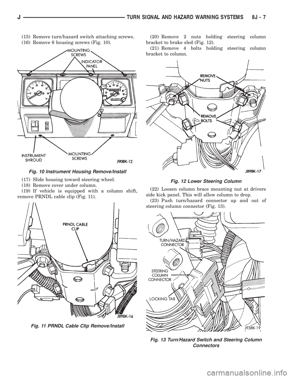
(15) Remove turn/hazard switch attaching screws.
(16) Remove 6 housing screws (Fig. 10).
(17) Slide housing toward steering wheel.
(18) Remove cover under column.
(19) If vehicle is equipped with a column shift,
remove PRNDL cable clip (Fig. 11).(20) Remove 2 nuts holding steering column
bracket to brake sled (Fig. 12).
(21) Remove 4 bolts holding steering column
bracket to column.
(22) Loosen column brace mounting nut at drivers
side kick panel. This will allow column to drop.
(23) Push turn/hazard connector up and out of
steering column connector (Fig. 13).
Fig. 10 Instrument Housing Remove/Install
Fig. 11 PRNDL Cable Clip Remove/Install
Fig. 12 Lower Steering Column
Fig. 13 Turn/Hazard Switch and Steering Column
Connectors
JTURN SIGNAL AND HAZARD WARNING SYSTEMS 8J - 7
Page 493 of 2158

RESTRAINT SYSTEMS
CONTENTS
page page
AIRBAG SYSTEM......................... 1
DIAGNOSIS............................. 2GENERAL INFORMATION.................. 1
SERVICE PROCEDURES................... 2
AIRBAG SYSTEM
WARNING: THIS AIRBAG SYSTEM IS A SENSITIVE,
COMPLEX MECHANICAL UNIT. BEFORE ATTEMPT-
ING TO REMOVE OR INSTALL THE AIRBAG SYS-
TEM OR RELATED STEERING WHEEL AND
STEERING COLUMN COMPONENTS YOU MUST
FIRST DISARM THE AIRBAG FIRING MECHANISM.
FAILURE TO DO SO COULD RESULT IN ACCIDEN-
TAL DEPLOYMENT AND POSSIBLE PERSONAL IN-
JURY.
WARNING: THE AIRBAG MODULE INFLATOR/SEN-
SOR ASSEMBLY CONTAINS SODIUM AZIDE AND
POTASSIUM NITRATE. THESE MATERIALS ARE
POISONOUS AND EXTREMELY FLAMMABLE. CON-
TACT WITH ACID, WATER OR HEAVY METALS MAY
PRODUCE HARMFUL AND IRRITATING GASES (SO-
DIUM HYDROXIDE IS FORMED IN THE PRESENCE
OF MOISTURE) OR COMBUSTIBLE COMPOUNDS.
DO NOT ATTEMPT TO DISMANTLE THE MODULE
OR TAMPER WITH ITS ARMING LEVER. DO NOT
PUNCTURE, INCINERATE, OR BRING INTO CON-
TACT WITH ELECTRICITY. DO NOT STORE AT TEM-
PERATURES EXCEEDING 200ÉF.WARNING: REPLACE AIRBAG SYSTEM COMPO-
NENTS WITH PARTS SPECIFIED IN THE CHRYSLER
MOPAR PARTS CATALOG ONLY. IT IS OF PARTICU-
LAR IMPORTANCE THAT ANY COMPONENTS USED
IN THIS MECHANICALLY-FIRED AIRBAG SYSTEM
NOT BE MIXED WITH COMPONENTS FROM AN
ELECTRICALLY-FIRED AIRBAG SYSTEM. SUBSTI-
TUTE PARTS MAY APPEAR THE SAME, BUT INTER-
NAL DIFFERENCES MAY RESULT IN INFERIOR
OCCUPANT PROTECTION.
WARNING: THE FASTENERS, SCREWS, AND
BOLTS, ORIGINALLY USED FOR THE AIRBAG COM-
PONENTS, HAVE SPECIAL COATINGS AND ARE
SPECIFICALLY DESIGNED FOR THE AIRBAG SYS-
TEM. THEY MUST NEVER BE REPLACED WITH ANY
SUBSTITUTES. ANYTIME A NEW FASTENER IS
NEEDED, REPLACE WITH THE CORRECT FASTEN-
ERS PROVIDED IN THE SERVICE PACKAGE OR
SPECIFIED IN THE CHRYSLER MOPAR PARTS CAT-
ALOG.
GENERAL INFORMATION
The airbag system is a standard equipment safety
device on XJ (Cherokee) models. It is designed to pro-
tect the driver from serious injury, caused by a fron-
tal impact of the vehicle. If the airbag module
assembly is defective and non-deployed, refer to
Chrysler Corporation current return list for proper
handling procedures.
Following are general descriptions of the major
components in the airbag system.AIRBAG MODULE
The airbag module protective cover is the only vis-
ible part of the system. The module is mounted di-
rectly to the steering wheel. Under the airbag
module cover, the airbag cushion and its supporting
components are contained. The airbag module con-
tains a housing to which the cushion and impact sen-
sor/inflator assembly are attached and sealed. The
airbag module is non-serviceable, and must be re-
placed if deployed or damaged in any way.
The impact sensor/inflator assembly is mounted to
the back of the module. The inflator seals the hole in
JRESTRAINT SYSTEMS 8M - 1
Page 1298 of 2158
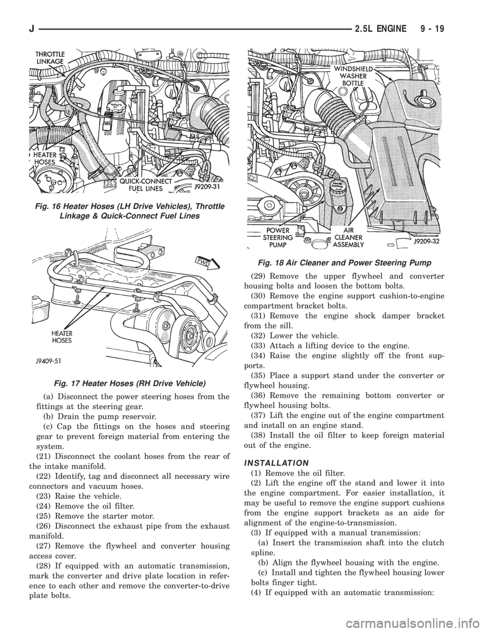
(a) Disconnect the power steering hoses from the
fittings at the steering gear.
(b) Drain the pump reservoir.
(c) Cap the fittings on the hoses and steering
gear to prevent foreign material from entering the
system.
(21) Disconnect the coolant hoses from the rear of
the intake manifold.
(22) Identify, tag and disconnect all necessary wire
connectors and vacuum hoses.
(23) Raise the vehicle.
(24) Remove the oil filter.
(25) Remove the starter motor.
(26) Disconnect the exhaust pipe from the exhaust
manifold.
(27) Remove the flywheel and converter housing
access cover.
(28) If equipped with an automatic transmission,
mark the converter and drive plate location in refer-
ence to each other and remove the converter-to-drive
plate bolts.(29) Remove the upper flywheel and converter
housing bolts and loosen the bottom bolts.
(30) Remove the engine support cushion-to-engine
compartment bracket bolts.
(31) Remove the engine shock damper bracket
from the sill.
(32) Lower the vehicle.
(33) Attach a lifting device to the engine.
(34) Raise the engine slightly off the front sup-
ports.
(35) Place a support stand under the converter or
flywheel housing.
(36) Remove the remaining bottom converter or
flywheel housing bolts.
(37) Lift the engine out of the engine compartment
and install on an engine stand.
(38) Install the oil filter to keep foreign material
out of the engine.
INSTALLATION
(1) Remove the oil filter.
(2) Lift the engine off the stand and lower it into
the engine compartment. For easier installation, it
may be useful to remove the engine support cushions
from the engine support brackets as an aide for
alignment of the engine-to-transmission.
(3) If equipped with a manual transmission:
(a) Insert the transmission shaft into the clutch
spline.
(b) Align the flywheel housing with the engine.
(c) Install and tighten the flywheel housing lower
bolts finger tight.
(4) If equipped with an automatic transmission:
Fig. 16 Heater Hoses (LH Drive Vehicles), Throttle
Linkage & Quick-Connect Fuel Lines
Fig. 17 Heater Hoses (RH Drive Vehicle)
Fig. 18 Air Cleaner and Power Steering Pump
J2.5L ENGINE 9 - 19
Page 1299 of 2158
(a) Align the transmission torque converter hous-
ing with the engine.
(b) Loosely install the converter housing lower
bolts and install the next higher bolt and nut on
each side.
(c) Tighten all 4 bolts finger-tight.
(5) Install the engine support cushions (if re-
moved).
(6) Lower the engine and engine support cushions
onto the engine compartment brackets.
(7) Remove the engine lifting device.
(8) Raise the vehicle.
(9) If equipped with an automatic transmission:
(a) Install the converter-to-drive plate bolts. En-
sure the installation reference marks are aligned.
Tighten the bolts to 54 Nzm (40 ft. lbs.) torque.
(b) Install the converter-housing access cover.
(c) Install the exhaust pipe support.
(10) Install the remaining converter or flywheel
housing bolts.
(11) Install the starter motor and connect the ca-
ble. Tighten the bolts to 45 Nzm (33 ft. lbs.) torque.
(12) Tighten the engine support cushing through-
bolt nuts.
(13) Install the remaining flywheel and converter
housing bolts. Tighten the bolts to 38 Nzm (28 ft. lbs.)
torque.
(14) Connect the exhaust pipe to the manifold.
(15) Install the oil filter.
(16) Lower the vehicle.
(17) Connect the coolant hoses and tighten the
clamps.
(18) If equipped with power steering:
(a) Remove the protective caps
(b) Connect the hoses to the fittings at the steer-
ing gear. Tighten the nut to 52 Nzm (38 ft. lbs.)
torque.
(c) Fill the pump reservoir with fluid.
(19) Remove the pulley-to-water pump flange
alignment capscrew and install the fan and spacer or
Tempatrol fan assembly.
(20) Install the fan shroud and radiator and con-
denser (if equipped with air conditioning).
(21) Connect the radiator hoses.
(22) Connect the automatic transmission fluid
cooler pipes, if equipped.
(23) Connect the oxygen sensor wire connector.
(24) Connect the throttle valve rod and retainer.
Connect the throttle cable and install the rod. Install
the throttle valve rod spring.
(25) Connect the speed control cable, if equipped.
(26) Connect the fuel supply and return lines to
the throttle body.
(27) Connect all the vacuum hoses and wire con-
nectors.
(28) Connect the service valves to the A/C compres-
sor ports, if equipped with air conditioning.(29) Fill the power steering reservoir.
(30) Connect the battery cables.
(31) Install the hood.
(32) Install the air cleaner.
(33) Start the engine and inspect for leaks.
(34) Fill the cooling system.
(35) Stop the engine and check the fluid levels.
Add fluid, as required.
ENGINE ASSEMBLYÐYJ VEHICLES
REMOVAL
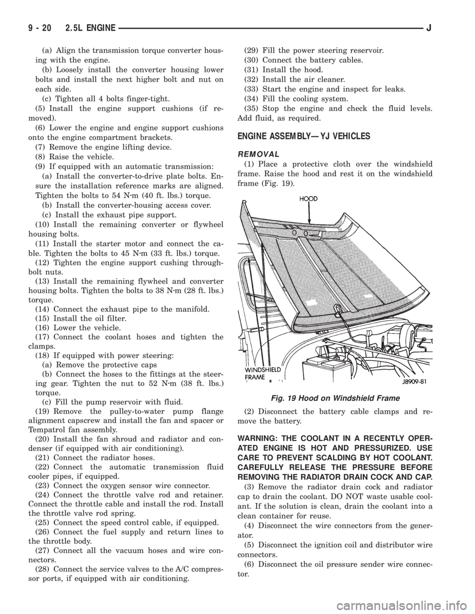
(1) Place a protective cloth over the windshield
frame. Raise the hood and rest it on the windshield
frame (Fig. 19).
(2) Disconnect the battery cable clamps and re-
move the battery.
WARNING: THE COOLANT IN A RECENTLY OPER-
ATED ENGINE IS HOT AND PRESSURIZED. USE
CARE TO PREVENT SCALDING BY HOT COOLANT.
CAREFULLY RELEASE THE PRESSURE BEFORE
REMOVING THE RADIATOR DRAIN COCK AND CAP.
(3) Remove the radiator drain cock and radiator
cap to drain the coolant. DO NOT waste usable cool-
ant. If the solution is clean, drain the coolant into a
clean container for reuse.
(4) Disconnect the wire connectors from the gener-
ator.
(5) Disconnect the ignition coil and distributor wire
connectors.
(6) Disconnect the oil pressure sender wire connec-
tor.
Fig. 19 Hood on Windshield Frame
9 - 20 2.5L ENGINEJ
Page 1300 of 2158
(7) Disconnect the wires at the starter motor sole-
noid and injection wire harness connector.
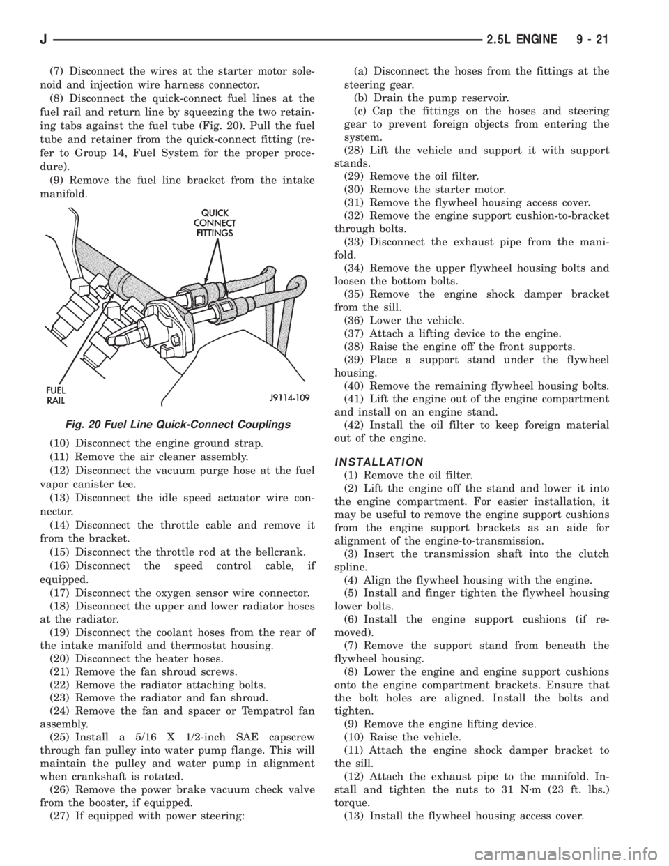
(8) Disconnect the quick-connect fuel lines at the
fuel rail and return line by squeezing the two retain-
ing tabs against the fuel tube (Fig. 20). Pull the fuel
tube and retainer from the quick-connect fitting (re-
fer to Group 14, Fuel System for the proper proce-
dure).
(9) Remove the fuel line bracket from the intake
manifold.
(10) Disconnect the engine ground strap.
(11) Remove the air cleaner assembly.
(12) Disconnect the vacuum purge hose at the fuel
vapor canister tee.
(13) Disconnect the idle speed actuator wire con-
nector.
(14) Disconnect the throttle cable and remove it
from the bracket.
(15) Disconnect the throttle rod at the bellcrank.
(16) Disconnect the speed control cable, if
equipped.
(17) Disconnect the oxygen sensor wire connector.
(18) Disconnect the upper and lower radiator hoses
at the radiator.
(19) Disconnect the coolant hoses from the rear of
the intake manifold and thermostat housing.
(20) Disconnect the heater hoses.
(21) Remove the fan shroud screws.
(22) Remove the radiator attaching bolts.
(23) Remove the radiator and fan shroud.
(24) Remove the fan and spacer or Tempatrol fan
assembly.
(25) Install a 5/16 X 1/2-inch SAE capscrew
through fan pulley into water pump flange. This will
maintain the pulley and water pump in alignment
when crankshaft is rotated.
(26) Remove the power brake vacuum check valve
from the booster, if equipped.
(27) If equipped with power steering:(a) Disconnect the hoses from the fittings at the
steering gear.
(b) Drain the pump reservoir.
(c) Cap the fittings on the hoses and steering
gear to prevent foreign objects from entering the
system.
(28) Lift the vehicle and support it with support
stands.
(29) Remove the oil filter.
(30) Remove the starter motor.
(31) Remove the flywheel housing access cover.
(32) Remove the engine support cushion-to-bracket
through bolts.
(33) Disconnect the exhaust pipe from the mani-
fold.
(34) Remove the upper flywheel housing bolts and
loosen the bottom bolts.
(35) Remove the engine shock damper bracket
from the sill.
(36) Lower the vehicle.
(37) Attach a lifting device to the engine.
(38) Raise the engine off the front supports.
(39) Place a support stand under the flywheel
housing.
(40) Remove the remaining flywheel housing bolts.
(41) Lift the engine out of the engine compartment
and install on an engine stand.
(42) Install the oil filter to keep foreign material
out of the engine.
INSTALLATION
(1) Remove the oil filter.
(2) Lift the engine off the stand and lower it into
the engine compartment. For easier installation, it
may be useful to remove the engine support cushions
from the engine support brackets as an aide for
alignment of the engine-to-transmission.
(3) Insert the transmission shaft into the clutch
spline.
(4) Align the flywheel housing with the engine.
(5) Install and finger tighten the flywheel housing
lower bolts.
(6) Install the engine support cushions (if re-
moved).
(7) Remove the support stand from beneath the
flywheel housing.
(8) Lower the engine and engine support cushions
onto the engine compartment brackets. Ensure that
the bolt holes are aligned. Install the bolts and
tighten.
(9) Remove the engine lifting device.
(10) Raise the vehicle.
(11) Attach the engine shock damper bracket to
the sill.
(12) Attach the exhaust pipe to the manifold. In-
stall and tighten the nuts to 31 Nzm (23 ft. lbs.)
torque.
(13) Install the flywheel housing access cover.
Fig. 20 Fuel Line Quick-Connect Couplings
J2.5L ENGINE 9 - 21