Page 1747 of 2158
Solenoid Testing
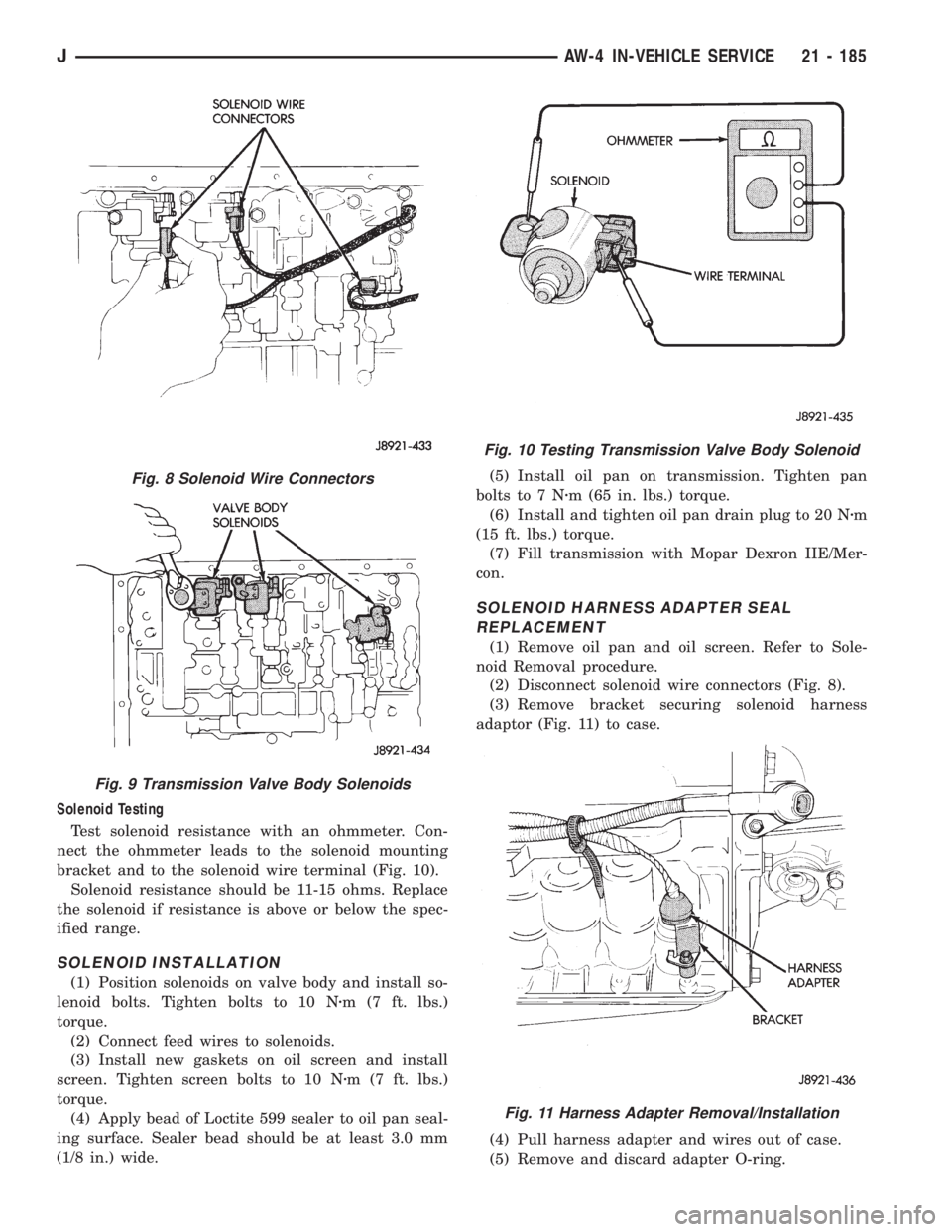
Test solenoid resistance with an ohmmeter. Con-
nect the ohmmeter leads to the solenoid mounting
bracket and to the solenoid wire terminal (Fig. 10).
Solenoid resistance should be 11-15 ohms. Replace
the solenoid if resistance is above or below the spec-
ified range.
SOLENOID INSTALLATION
(1) Position solenoids on valve body and install so-
lenoid bolts. Tighten bolts to 10 Nzm (7 ft. lbs.)
torque.
(2) Connect feed wires to solenoids.
(3) Install new gaskets on oil screen and install
screen. Tighten screen bolts to 10 Nzm (7 ft. lbs.)
torque.
(4) Apply bead of Loctite 599 sealer to oil pan seal-
ing surface. Sealer bead should be at least 3.0 mm
(1/8 in.) wide.(5) Install oil pan on transmission. Tighten pan
bolts to 7 Nzm (65 in. lbs.) torque.
(6) Install and tighten oil pan drain plug to 20 Nzm
(15 ft. lbs.) torque.
(7) Fill transmission with Mopar Dexron IIE/Mer-
con.
SOLENOID HARNESS ADAPTER SEAL
REPLACEMENT
(1) Remove oil pan and oil screen. Refer to Sole-
noid Removal procedure.
(2) Disconnect solenoid wire connectors (Fig. 8).
(3) Remove bracket securing solenoid harness
adaptor (Fig. 11) to case.
(4) Pull harness adapter and wires out of case.
(5) Remove and discard adapter O-ring.
Fig. 10 Testing Transmission Valve Body Solenoid
Fig. 11 Harness Adapter Removal/Installation
Fig. 8 Solenoid Wire Connectors
Fig. 9 Transmission Valve Body Solenoids
JAW-4 IN-VEHICLE SERVICE 21 - 185
Page 1748 of 2158
(6) Lubricate new O-ring and install it on adapter.
(7) Install solenoid wire harness and adapter in
case.
(8) Install adapter bracket and bracket bolt.
(9) Connect wires to solenoids.
(10) Install oil screen and oil pan.
TRANSMISSION VALVE BODY REMOVAL
Removal and installation are the only valve body
service procedures covered in this section. Refer to
the transmission overhaul section for valve body dis-
assembly, cleaning, inspection and reassembly.
(1) Remove oil pan plug and drain transmission
fluid.
(2) Remove oil pan and oil screen. Clean pan and
screen in solvent and dry them with compressed air.
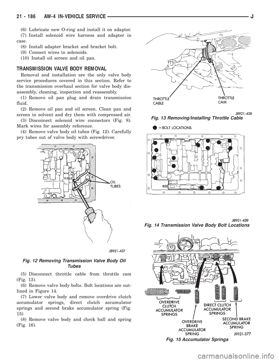
(3) Disconnect solenoid wire connectors (Fig. 8).
Mark wires for assembly reference.
(4) Remove valve body oil tubes (Fig. 12). Carefully
pry tubes out of valve body with screwdriver.
(5) Disconnect throttle cable from throttle cam
(Fig. 13).
(6) Remove valve body bolts. Bolt locations are out-
lined in Figure 14.
(7) Lower valve body and remove overdrive clutch
accumulator springs, direct clutch accumulator
springs and second brake accumulator spring (Fig.
15)
(8) Remove valve body and check ball and spring
(Fig. 16).
Fig. 13 Removing/Installing Throttle Cable
Fig. 14 Transmission Valve Body Bolt Locations
Fig. 15 Accumulator Springs
Fig. 12 Removing Transmission Valve Body Oil
Tubes
21 - 186 AW-4 IN-VEHICLE SERVICEJ
Page 1749 of 2158
TRANSMISSION VALVE BODY INSTALLATION
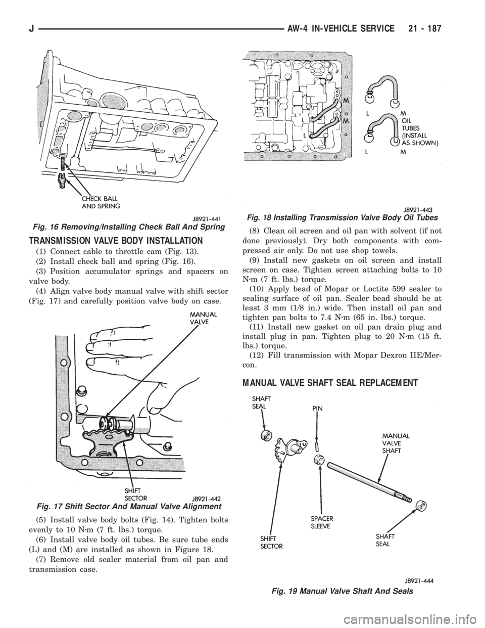
(1) Connect cable to throttle cam (Fig. 13).
(2) Install check ball and spring (Fig. 16).
(3) Position accumulator springs and spacers on
valve body.
(4) Align valve body manual valve with shift sector
(Fig. 17) and carefully position valve body on case.
(5) Install valve body bolts (Fig. 14). Tighten bolts
evenly to 10 Nzm (7 ft. lbs.) torque.
(6) Install valve body oil tubes. Be sure tube ends
(L) and (M) are installed as shown in Figure 18.
(7) Remove old sealer material from oil pan and
transmission case.(8) Clean oil screen and oil pan with solvent (if not
done previously). Dry both components with com-
pressed air only. Do not use shop towels.
(9) Install new gaskets on oil screen and install
screen on case. Tighten screen attaching bolts to 10
Nzm (7 ft. lbs.) torque.
(10) Apply bead of Mopar or Loctite 599 sealer to
sealing surface of oil pan. Sealer bead should be at
least 3 mm (1/8 in.) wide. Then install oil pan and
tighten pan bolts to 7.4 Nzm (65 in. lbs.) torque.
(11) Install new gasket on oil pan drain plug and
install plug in pan. Tighten plug to 20 Nzm (15 ft.
lbs.) torque.
(12) Fill transmission with Mopar Dexron IIE/Mer-
con.
MANUAL VALVE SHAFT SEAL REPLACEMENT
Fig. 16 Removing/Installing Check Ball And Spring
Fig. 17 Shift Sector And Manual Valve Alignment
Fig. 18 Installing Transmission Valve Body Oil Tubes
Fig. 19 Manual Valve Shaft And Seals
JAW-4 IN-VEHICLE SERVICE 21 - 187
Page 1750 of 2158
(1) Remove park/neutral position switch and dis-
connect transmission shift lever.
(2) Remove oil pan and valve body.
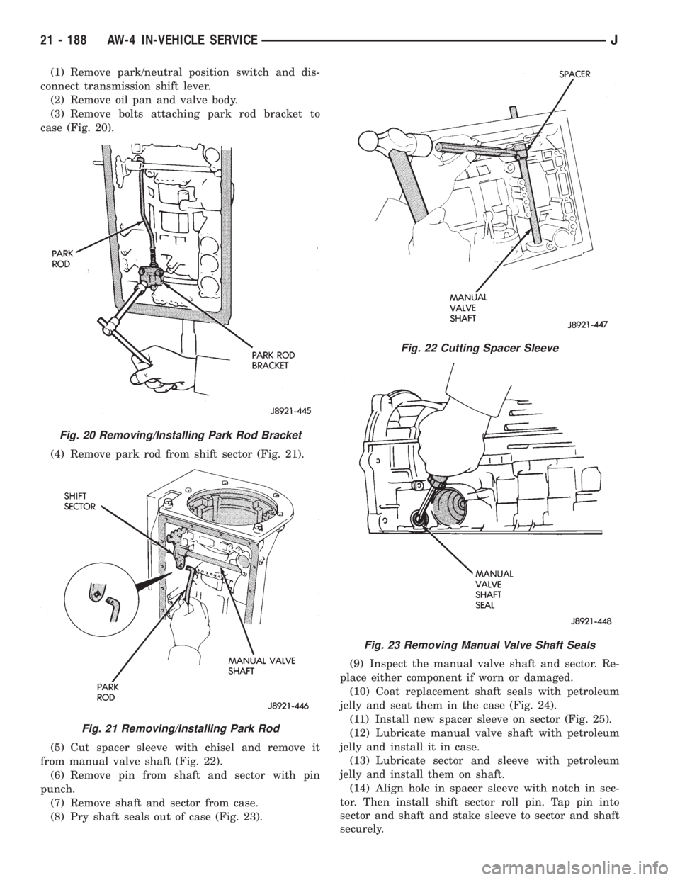
(3) Remove bolts attaching park rod bracket to
case (Fig. 20).
(4) Remove park rod from shift sector (Fig. 21).
(5) Cut spacer sleeve with chisel and remove it
from manual valve shaft (Fig. 22).
(6) Remove pin from shaft and sector with pin
punch.
(7) Remove shaft and sector from case.
(8) Pry shaft seals out of case (Fig. 23).(9) Inspect the manual valve shaft and sector. Re-
place either component if worn or damaged.
(10) Coat replacement shaft seals with petroleum
jelly and seat them in the case (Fig. 24).
(11) Install new spacer sleeve on sector (Fig. 25).
(12) Lubricate manual valve shaft with petroleum
jelly and install it in case.
(13) Lubricate sector and sleeve with petroleum
jelly and install them on shaft.
(14) Align hole in spacer sleeve with notch in sec-
tor. Then install shift sector roll pin. Tap pin into
sector and shaft and stake sleeve to sector and shaft
securely.
Fig. 20 Removing/Installing Park Rod Bracket
Fig. 21 Removing/Installing Park Rod
Fig. 22 Cutting Spacer Sleeve
Fig. 23 Removing Manual Valve Shaft Seals
21 - 188 AW-4 IN-VEHICLE SERVICEJ
Page 1751 of 2158
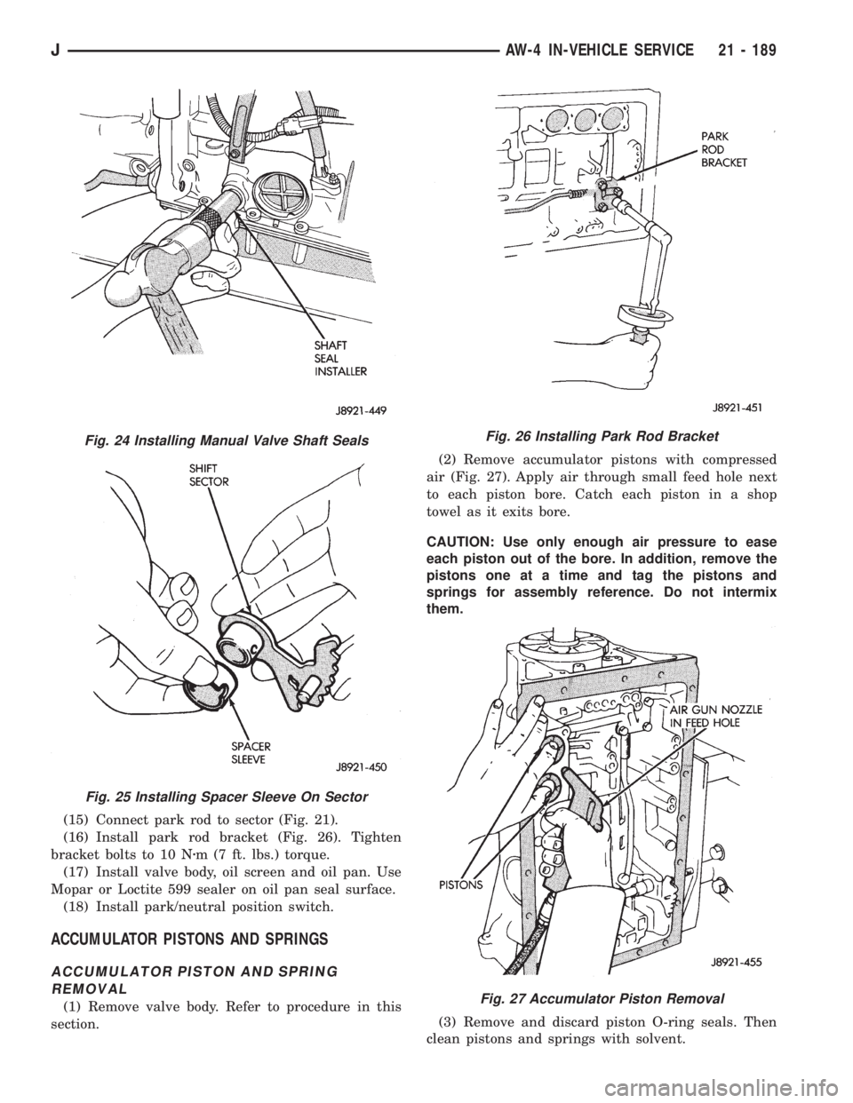
(15) Connect park rod to sector (Fig. 21).
(16) Install park rod bracket (Fig. 26). Tighten
bracket bolts to 10 Nzm (7 ft. lbs.) torque.
(17) Install valve body, oil screen and oil pan. Use
Mopar or Loctite 599 sealer on oil pan seal surface.
(18) Install park/neutral position switch.
ACCUMULATOR PISTONS AND SPRINGS
ACCUMULATOR PISTON AND SPRING
REMOVAL
(1) Remove valve body. Refer to procedure in this
section.(2) Remove accumulator pistons with compressed
air (Fig. 27). Apply air through small feed hole next
to each piston bore. Catch each piston in a shop
towel as it exits bore.
CAUTION: Use only enough air pressure to ease
each piston out of the bore. In addition, remove the
pistons one at a time and tag the pistons and
springs for assembly reference. Do not intermix
them.
(3) Remove and discard piston O-ring seals. Then
clean pistons and springs with solvent.
Fig. 24 Installing Manual Valve Shaft Seals
Fig. 25 Installing Spacer Sleeve On Sector
Fig. 26 Installing Park Rod Bracket
Fig. 27 Accumulator Piston Removal
JAW-4 IN-VEHICLE SERVICE 21 - 189
Page 1752 of 2158
(4) Inspect pistons, springs and piston bores. Re-
place worn damaged pistons. Replace broken, col-
lapsed or distorted springs. Replace case if piston
bores are damaged.
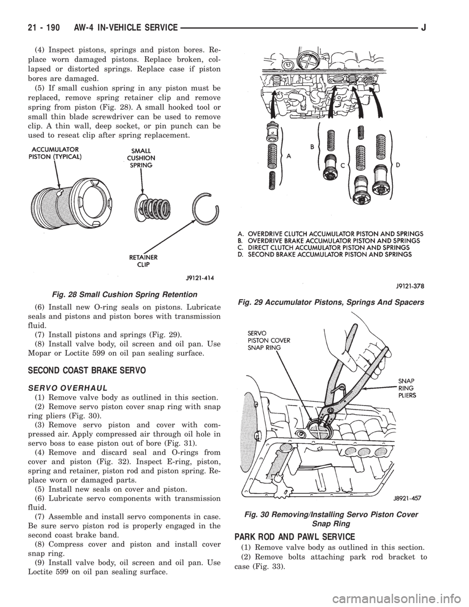
(5) If small cushion spring in any piston must be
replaced, remove spring retainer clip and remove
spring from piston (Fig. 28). A small hooked tool or
small thin blade screwdriver can be used to remove
clip. A thin wall, deep socket, or pin punch can be
used to reseat clip after spring replacement.
(6) Install new O-ring seals on pistons. Lubricate
seals and pistons and piston bores with transmission
fluid.
(7) Install pistons and springs (Fig. 29).
(8) Install valve body, oil screen and oil pan. Use
Mopar or Loctite 599 on oil pan sealing surface.
SECOND COAST BRAKE SERVO
SERVO OVERHAUL
(1) Remove valve body as outlined in this section.
(2) Remove servo piston cover snap ring with snap
ring pliers (Fig. 30).
(3) Remove servo piston and cover with com-
pressed air. Apply compressed air through oil hole in
servo boss to ease piston out of bore (Fig. 31).
(4) Remove and discard seal and O-rings from
cover and piston (Fig. 32). Inspect E-ring, piston,
spring and retainer, piston rod and piston spring. Re-
place worn or damaged parts.
(5) Install new seals on cover and piston.
(6) Lubricate servo components with transmission
fluid.
(7) Assemble and install servo components in case.
Be sure servo piston rod is properly engaged in the
second coast brake band.
(8) Compress cover and piston and install cover
snap ring.
(9) Install valve body, oil screen and oil pan. Use
Loctite 599 on oil pan sealing surface.
PARK ROD AND PAWL SERVICE
(1) Remove valve body as outlined in this section.
(2) Remove bolts attaching park rod bracket to
case (Fig. 33).
Fig. 29 Accumulator Pistons, Springs And Spacers
Fig. 30 Removing/Installing Servo Piston Cover
Snap Ring
Fig. 28 Small Cushion Spring Retention
21 - 190 AW-4 IN-VEHICLE SERVICEJ
Page 1753 of 2158
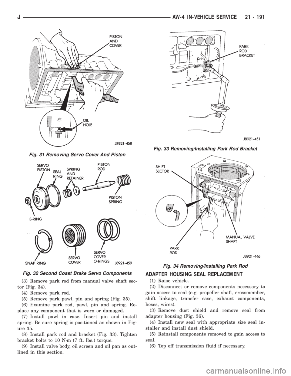
(3) Remove park rod from manual valve shaft sec-
tor (Fig. 34).
(4) Remove park rod.
(5) Remove park pawl, pin and spring (Fig. 35).
(6) Examine park rod, pawl, pin and spring. Re-
place any component that is worn or damaged.
(7) Install pawl in case. Insert pin and install
spring. Be sure spring is positioned as shown in Fig-
ure 35.
(8) Install park rod and bracket (Fig. 33). Tighten
bracket bolts to 10 Nzm (7 ft. lbs.) torque.
(9) Install valve body, oil screen and oil pan as out-
lined in this section.
ADAPTER HOUSING SEAL REPLACEMENT
(1) Raise vehicle.
(2) Disconnect or remove components necessary to
gain access to seal (e.g. propeller shaft, crossmember,
shift linkage, transfer case, exhaust components,
hoses, wires).
(3) Remove dust shield and remove seal from
adapter housing (Fig. 36).
(4) Install new seal with appropriate size seal in-
staller and install dust shield.
(5) Reinstall components removed to gain access to
seal.
(6) Top off transmission fluid if necessary.
Fig. 31 Removing Servo Cover And Piston
Fig. 32 Second Coast Brake Servo Components
Fig. 33 Removing/Installing Park Rod Bracket
Fig. 34 Removing/Installing Park Rod
JAW-4 IN-VEHICLE SERVICE 21 - 191
Page 1754 of 2158
SPEED SENSOR
SPEED SENSOR TESTING
Test the speed sensor with an ohmmeter. Place the
ohmmeter leads on the terminals in the sensor con-
nector (Fig. 37).
Rotate the transmission output shaft and observe
the ohmmeter needle. The needle should deflect indi-
cating the switch is opening/closing as the rotormoves past the sensor (Fig. 37). Replace the sensor if
the ohmmeter does not display any kind of reading.
If a digital ohmmeter is being used, the sensor
should generate an ohmmeter readout each time the
switch opens and closes.
SPEED SENSOR REPLACEMENT
(1) Disconnect sensor wire harness connector.
(2) Remove sensor retainer bolt and remove sensor
(Fig. 38).
(3) Remove and discard speed sensor O-ring.
Fig. 35 Removing/Installing Park Pawl, Pin And
Spring
Fig. 36 Adapter Housing Seals
Fig. 37 Speed Sensor Testing
Fig. 38 Transmission Speed Sensor Removal/
Installation
21 - 192 AW-4 IN-VEHICLE SERVICEJ