1995 JEEP YJ service
[x] Cancel search: servicePage 1874 of 2158
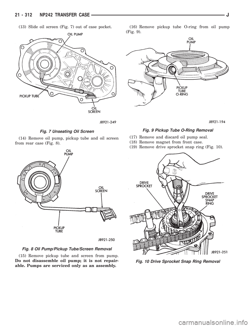
(13) Slide oil screen (Fig. 7) out of case pocket.
(14) Remove oil pump, pickup tube and oil screen
from rear case (Fig. 8).
(15) Remove pickup tube and screen from pump.
Do not disassemble oil pump; it is not repair-
able. Pumps are serviced only as an assembly.(16) Remove pickup tube O-ring from oil pump
(Fig. 9).
(17) Remove and discard oil pump seal.
(18) Remove magnet from front case.
(19) Remove drive sprocket snap ring (Fig. 10).
Fig. 7 Unseating Oil Screen
Fig. 8 Oil Pump/Pickup Tube/Screen Removal
Fig. 9 Pickup Tube O-Ring Removal
Fig. 10 Drive Sprocket Snap Ring Removal
21 - 312 NP242 TRANSFER CASEJ
Page 1880 of 2158
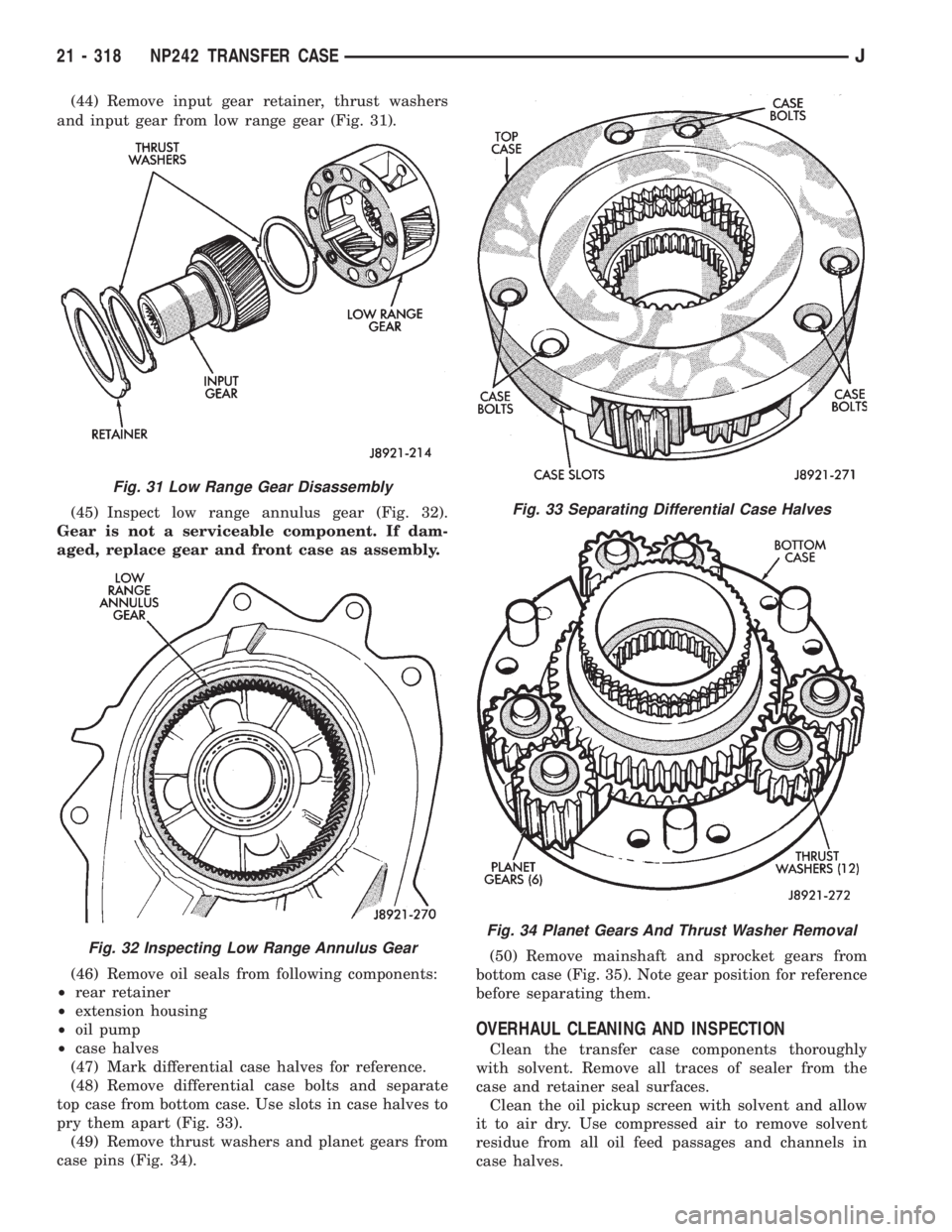
(44) Remove input gear retainer, thrust washers
and input gear from low range gear (Fig. 31).
(45) Inspect low range annulus gear (Fig. 32).
Gear is not a serviceable component. If dam-
aged, replace gear and front case as assembly.
(46) Remove oil seals from following components:
²rear retainer
²extension housing
²oil pump
²case halves
(47) Mark differential case halves for reference.
(48) Remove differential case bolts and separate
top case from bottom case. Use slots in case halves to
pry them apart (Fig. 33).
(49) Remove thrust washers and planet gears from
case pins (Fig. 34).(50) Remove mainshaft and sprocket gears from
bottom case (Fig. 35). Note gear position for reference
before separating them.
OVERHAUL CLEANING AND INSPECTION
Clean the transfer case components thoroughly
with solvent. Remove all traces of sealer from the
case and retainer seal surfaces.
Clean the oil pickup screen with solvent and allow
it to air dry. Use compressed air to remove solvent
residue from all oil feed passages and channels in
case halves.
Fig. 31 Low Range Gear Disassembly
Fig. 32 Inspecting Low Range Annulus Gear
Fig. 33 Separating Differential Case Halves
Fig. 34 Planet Gears And Thrust Washer Removal
21 - 318 NP242 TRANSFER CASEJ
Page 1912 of 2158
WHEELS
GENERAL INFORMATION
Original equipment wheels are designed for the
specified Maximum Vehicle Capacity.
All models use steel or cast aluminum drop center
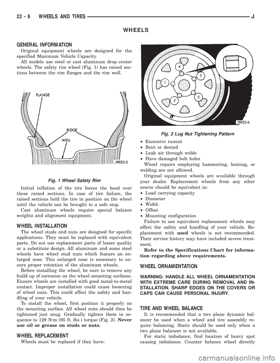
wheels. The safety rim wheel (Fig. 1) has raised sec-
tions between the rim flanges and the rim well.
Initial inflation of the tire forces the bead over
these raised sections. In case of tire failure, the
raised sections hold the tire in position on the wheel
until the vehicle can be brought to a safe stop.
Cast aluminum wheels require special balance
weights and alignment equipment.
WHEEL INSTALLATION
The wheel studs and nuts are designed for specific
applications. They must be replaced with equivalent
parts. Do not use replacement parts of lesser quality
or a substitute design. All aluminum and some steel
wheels have wheel stud nuts which feature an en-
larged nose. This enlarged nose is necessary to en-
sure proper retention of the aluminum wheels.
Before installing the wheel, be sure to remove any
build up of corrosion on the wheel mounting surfaces.
Ensure wheels are installed with good metal-to-metal
contact. Improper installation could cause loosening
of wheel nuts. This could affect the safety and han-
dling of your vehicle.
To install the wheel, first position it properly on
the mounting surface. All wheel nuts should then be
tightened just snug. Gradually tighten them in se-
quence to 129 Nzm (95 ft. lbs.) torque (Fig. 2).Never
use oil or grease on studs or nuts.
WHEEL REPLACEMENT
Wheels must be replaced if they have:²Excessive runout
²Bent or dented
²Leak air through welds
²Have damaged bolt holes
Wheel repairs employing hammering, heating, or
welding are not allowed.
Original equipment wheels are available through
your dealer. Replacement wheels from any other
source should be equivalent in:
²Load carrying capacity
²Diameter
²Width
²Offset
²Mounting configuration
Failure to use equivalent replacement wheels may
affect the safety and handling of your vehicle. Re-
placement withusedwheels is not recommended.
Their service history may have included severe treat-
ment.
Refer to the Specifications Chart for informa-
tion regarding above requirements.
WHEEL ORNAMENTATION
WARNING: HANDLE ALL WHEEL ORNAMENTATION
WITH EXTREME CARE DURING REMOVAL AND IN-
STALLATION. SHARP EDGES ON THE COVERS OR
CAPS CAN CAUSE PERSONAL INJURY.
TIRE AND WHEEL BALANCE
It is recommended that a two plane dynamic bal-
ancer be used when a wheel and tire assembly re-
quire balancing. Static should be used only when a
two plane balancer is not available.
For static imbalance, find location of heavy spot
causing imbalance. Counter balance wheel directly
Fig. 1 Wheel Safety Rim
Fig. 2 Lug Nut Tightening Pattern
22 - 6 WHEELS AND TIRESJ
Page 1919 of 2158
BODY COMPONENTSÐXJ VEHICLES
CONTENTS
page page
DOORS................................ 30
EXTERIOR COMPONENTS.................. 3
GENERAL BODY SERVICE INFORMATION..... 1INTERIOR COMPONENTS................. 80
STATIONARY WINDOW GLASS............. 66
TRAILER HITCH......................... 77
GENERAL BODY SERVICE INFORMATION
RIGHT HAND DRIVE VEHICLES
The XJ Body Components procedures in this sec-
tion were developed on a left hand drive (LHD) vehi-
cle. Unless a component is unique to a right hand
drive vehicle, it will not be specifically covered in this
section, i.e. cargo barrier. In general, components on
left hand drive vehicles will be located on the oppo-
site side in right hand drive vehicles.
LABELS/DECALS/PLATESÐXJ
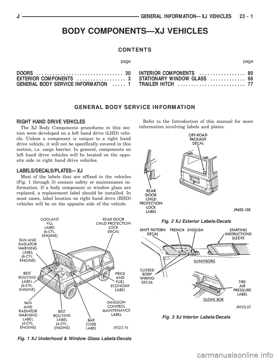
Most of the labels that are affixed to the vehicles
(Fig. 1 through 5) contain safety or maintenance in-
formation. If a body component or window glass are
replaced, a replacement label should be installed. In
most cases, label location on right hand drive (RHD)
vehicles will be on the opposite side of the vehicle.Refer to the Introduction of this manual for more
information involving labels and plates.
Fig. 1 XJ Underhood & Window Glass Labels/Decals
Fig. 2 XJ Exterior Labels/Decals
Fig. 3 XJ Interior Labels/Decals
JGENERAL INFORMATIONÐXJ VEHICLES 23 - 1
Page 1925 of 2158
INSTALLATION
(1) If removed, install the horns, baffle braces and
the wire harnesses on the baffles (Fig. 11).
(2) Position the radiator and the radiator support
crossmember at the front of vehicle (Fig. 10). Install
and tighten screws to 9 Nzm (76 in-lbs) torque.
(3) For 2.5L engines, install the power steering
pump reservoir on the left filler panel (Fig. 9).
(4) Install the grille opening panel (GOP).
HOODÐXJ
The hood service procedures included in this sec-
tion include:
²Hood removal and installation.
²Hood adjustment.
²HingeÐlatchÐstriker service (Fig. 12).
²Latch release cable service.
JEXTERIOR COMPONENTSÐXJ 23 - 7
Page 1939 of 2158
(4) If the original molding will be installed, also re-
move all adhesive from it.
INSTALLATION
(1) Install 3M 06379 double-sided tape on the
molding.
(2) For vertical alignment, use masking tape or a
string as reference.
(3) Remove the backing from the tape, align the
molding and position it on the body panel.
(4) Press the molding onto the body panel with a
roller or hand pressure.
BODY STRIPES/DECALSÐXJ
SERVICE INFORMATION
XJ body stripes and decals are weather resistant
tape with a adhesive backing.
REPAIR
Small nicks, scratches and other surface marks in
a body stripe/decal can be touched-up with paint.
To eliminate blisters and air bubbles in a body
stripe/decal, pierce them with a needle or pin.
A heat gun can also be used to remove small wrin-
kles in a stripe/decal.
REQUIREMENTS
Body stripe/decal replacement requires that the
metal repair and paint refinish be completed first.
The work area temperature should be between
18ÉC (65ÉF) and 32ÉC (90ÉF).A tape stripe/decal
should not be replaced if the work area temper-
ature is less than 18ÉC (65ÉF).
The following equipment and material are neces-
sary for removal and installation:
²Commercial tape stripe/decal removal solution.
²Commercial adhesive removal solution.
²Liquid dish detergent (for the wetting solution).
²Mixture of wetting solution.
²Commercial wax and silicone removal solution.
²Isopropyl (rubbing) alcohol.
²Small squeegee (plastic or hard rubber).
²Water bucket and sponge.
²Clean wiping rags or paper towels.
²Heat gun (or infra-red heat bulb).
²Wax pencil.
²
Sharp knife, single edge razor blade or X-acto knife.
²Pair of scissors.
²Needle or pin.
The use of a wetting solution aids the installation of a
tape stripe/decal on a painted panel. Prepare the wet-
ting solution by mixing two or three teaspoons of dish
detergent with 1 gallon of water.Do not use soap.
Too much detergent will reduce the effective-
ness of the mixture.
REMOVAL
(1) Clean the repaired surface, adjacent panels and
door the openings as necessary.
(2) Start at one end of the tape stripe/decal and
apply heat with a heat gun. Slowly peel the stripe/
decal from the panel by pulling it back.Do not pull
the tape stripe/decal outward from panel.
WARNING: USE TAPE STRIPE/DECAL REMOVAL
SOLUTION IN A WELL-VENTILATED AREA ONLY.
(3) A tape stripe/decal removal solution can be used
for removal at areas where a heat gun is ineffective:
²Mask-off the body panel area surrounding the tape
stripe/decal (Fig. 1).
²Move solution spray across the complete length of
stripe/decal with a steady motion.
²Ensure that the complete stripe/decal is covered
with solution.
²Allow stripe/decal removal solution to remain on
the stripe/decal for 20 minutes.
²After 20 minutes, peel the stripe/decal away from
flange area (Fig. 2).
Fig. 1 Stripe/Decal Removal Solution Application
Fig. 2 Body Stripe/Decal Removal
JEXTERIOR COMPONENTSÐXJ 23 - 21
Page 1944 of 2158
(3) Pull downward and remove the grille from ex-
haust port in the door opening panel.
INSTALLATION
(1) Position the slot located in the upper end of re-
placement grille at the exhaust port and insert edge
in the slot.
(2) Push inward and seat the grille in the exhaust
port.
(3) Install the screw to attach the grille to the door
opening panel.
EXTERIOR NAMEPLATESÐXJ
SERVICE INFORMATION
All of nameplates, with the exception of the JEEP
nameplate located on the grille are attached with ad-
hesive (Fig. 18).
GRILLE OPENING PANEL NAMEPLATE
REMOVAL
(1) Remove the grille opening panel (GOP) support
bracket.
(2) As applicable, remove the nut(s) from the let-
ter(s) that must be replaced.
(3) Remove the nameplate letter(s) from GOP.
INSTALLATION
(1) Clean the panel surface.
(2) Position the replacement letter(s) on the GOP.
(3) Install the nut(s) and tighten.
ADHESIVE-BACKED NAMEPLATES
REMOVAL/INSTALLATION
(1) Pry the nameplate from vehicle panel.
(2) Clean the panel surface.
(3) Position the replacement nameplate on the
panel push inward to seat it.
FUEL FILLER NOZZLE/TUBEÐXJ
REMOVAL
(1) Remove the fuel filler door from the quarter
panel (Fig. 19).
(2) For XJ vehicles, remove the fuel filler hose
splash shield from the quarter inner panel and frame
rail (Fig. 20).
(3) Remove the cap from the nozzle (Fig. 21).
(3) Loosen the clamps and separate the hoses from
the tubes.
(4) Remove the screws that attach the nozzle to
the housing.
(5) Remove the nozzle/tube from the fuel filler
housing (Fig. 22).
INSTALLATION
(1) Insert the fuel filler nozzle/tube into the hous-
ing.
(2) Install the screws to attach the nozzle/tube to
the housing. Tighten screws to 2 Nzm (20 in-lbs)
torque.
Fig. 18 XJ Exterior Nameplates
Fig. 19 Fuel Filler DoorÐTypical
Fig. 20 Fuel Filler Hose Splash ShieldÐXJ Vehicles
23 - 26 EXTERIOR COMPONENTSÐXJJ
Page 1945 of 2158
(3) Attach the hoses to the tubes with clamps.
Tighten the clamp screws to 4 Nzm (35 in-lbs) torque.
(4) Install the cap on nozzle.
(5) Install the fuel filler hose splash shield on the
quarter inner panel and frame rail.
(6) Install the fuel filler door on the quarter panel.
FUEL FILLER DOOR BUMPERSÐXJ
REPLACEMENT
(1) Grasp the bumper (Fig. 23) with pliers and pull
outward to remove it from the hole.
²It may be necessary to remove the door (Fig. 24) to
replace the door-stop bumper.
(2) Insert bumpers in the holes and force them in-
ward until they are seated in the holes.
EXTERNAL MIRRORSÐXJ
SERVICE INFORMATION
Service procedures for all external rear view mir-
rors are below.
REMOTE AND POWER/MANUAL MIRRORS
REMOVAL
(1) Remove the door trim panel.
(2) Remove the mirror inside trim cover screw (Fig.
1).
Fig. 21 Fuel Filler Nozzle/TubeÐXJ Vehicles
Fig. 22 Fuel Filler Nozzle/Tube Removal/
InstallationÐXJ Vehicles
Fig. 23 Fuel Filler Door Bumpers
Fig. 24 Fuel Filler Door-Stop Bumper
Fig. 1 Remote MirrorsÐPower/Manual
JEXTERIOR COMPONENTSÐXJ 23 - 27