1995 JEEP YJ service
[x] Cancel search: servicePage 2043 of 2158
(8) Separate the liftgate glass from the hard top.
(9) Remove the weatherstrip seal (Fig. 2), if neces-
sary.
INSTALLATION
(1) Assemble the liftgate components, if necessary
(2) Position the liftgate glass in the hard top open-
ing and install the hinge bolts. Do not tighten the
bolts.
(3) Adjust the liftgate glass to fit the hard top
opening.
(4) Tighten the hinge bolts to 11 Nzm (95 in-lbs)
torque.
(5) Position the support rod cylinders on the ball
studs.
(6) Install the support rod cylinder retainer clips.
(7) Connect the wiper motor wire harness connec-
tor and the washer fluid hose. Install the wiper mo-
tor cover (Fig. 1).
(8) Install the wiper arm and blade.
(9) Connect the rear window defroster/dome lamp
wire harness connectors.
DISASSEMBLY
(1) Remove retaining screws and the lower, inner
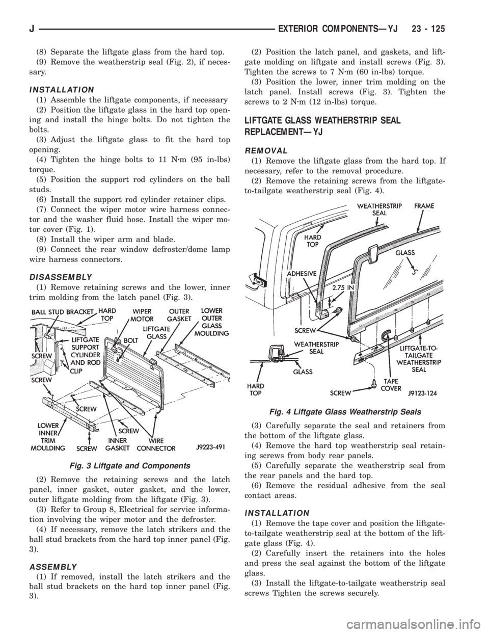
trim molding from the latch panel (Fig. 3).
(2) Remove the retaining screws and the latch
panel, inner gasket, outer gasket, and the lower,
outer liftgate molding from the liftgate (Fig. 3).
(3) Refer to Group 8, Electrical for service informa-
tion involving the wiper motor and the defroster.
(4) If necessary, remove the latch strikers and the
ball stud brackets from the hard top inner panel (Fig.
3).
ASSEMBLY
(1) If removed, install the latch strikers and the
ball stud brackets on the hard top inner panel (Fig.
3).(2) Position the latch panel, and gaskets, and lift-
gate molding on liftgate and install screws (Fig. 3).
Tighten the screws to 7 Nzm (60 in-lbs) torque.
(3) Position the lower, inner trim molding on the
latch panel. Install screws (Fig. 3). Tighten the
screws to 2 Nzm (12 in-lbs) torque.
LIFTGATE GLASS WEATHERSTRIP SEAL
REPLACEMENTÐYJ
REMOVAL
(1) Remove the liftgate glass from the hard top. If
necessary, refer to the removal procedure.
(2) Remove the retaining screws from the liftgate-
to-tailgate weatherstrip seal (Fig. 4).
(3) Carefully separate the seal and retainers from
the bottom of the liftgate glass.
(4) Remove the hard top weatherstrip seal retain-
ing screws from body rear panels.
(5) Carefully separate the weatherstrip seal from
the rear panels and the hard top.
(6) Remove the residual adhesive from the seal
contact areas.
INSTALLATION
(1) Remove the tape cover and position the liftgate-
to-tailgate weatherstrip seal at the bottom of the lift-
gate glass (Fig. 4).
(2) Carefully insert the retainers into the holes
and press the seal against the bottom of the liftgate
glass.
(3) Install the liftgate-to-tailgate weatherstrip seal
screws Tighten the screws securely.
Fig. 3 Liftgate and Components
Fig. 4 Liftgate Glass Weatherstrip Seals
JEXTERIOR COMPONENTSÐYJ 23 - 125
Page 2044 of 2158
(4) Apply weatherstrip adhesive to the hard top
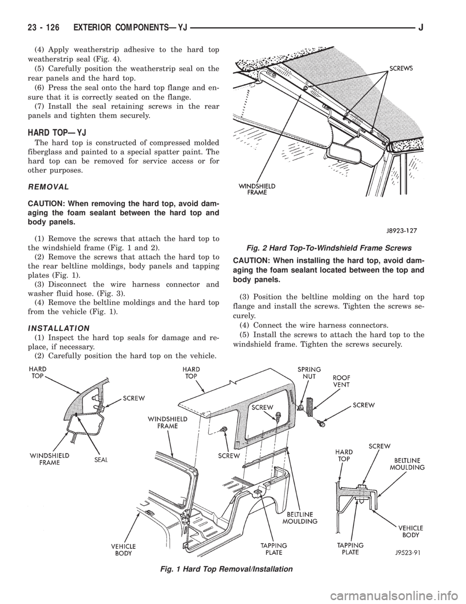
weatherstrip seal (Fig. 4).
(5) Carefully position the weatherstrip seal on the
rear panels and the hard top.
(6) Press the seal onto the hard top flange and en-
sure that it is correctly seated on the flange.
(7) Install the seal retaining screws in the rear
panels and tighten them securely.
HARD TOPÐYJ
The hard top is constructed of compressed molded
fiberglass and painted to a special spatter paint. The
hard top can be removed for service access or for
other purposes.
REMOVAL
CAUTION: When removing the hard top, avoid dam-
aging the foam sealant between the hard top and
body panels.
(1) Remove the screws that attach the hard top to
the windshield frame (Fig. 1 and 2).
(2) Remove the screws that attach the hard top to
the rear beltline moldings, body panels and tapping
plates (Fig. 1).
(3) Disconnect the wire harness connector and
washer fluid hose. (Fig. 3).
(4) Remove the beltline moldings and the hard top
from the vehicle (Fig. 1).
INSTALLATION
(1) Inspect the hard top seals for damage and re-
place, if necessary.
(2) Carefully position the hard top on the vehicle.CAUTION: When installing the hard top, avoid dam-
aging the foam sealant located between the top and
body panels.
(3) Position the beltline molding on the hard top
flange and install the screws. Tighten the screws se-
curely.
(4) Connect the wire harness connectors.
(5) Install the screws to attach the hard top to the
windshield frame. Tighten the screws securely.
Fig. 1 Hard Top Removal/Installation
Fig. 2 Hard Top-To-Windshield Frame Screws
23 - 126 EXTERIOR COMPONENTSÐYJJ
Page 2045 of 2158
HARD TOP ROOF VENTÐYJ
REMOVAL/INSTALLATION
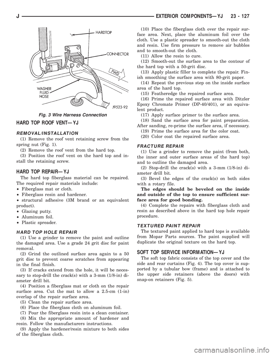
(1) Remove the roof vent retaining screw from the
spring nut (Fig. 1).
(2) Remove the roof vent from the hard top.
(3) Position the roof vent on the hard top and in-
stall the retaining screw.
HARD TOP REPAIRÐYJ
The hard top fiberglass material can be repaired.
The required repair materials include:
²Fiberglass mat or cloth.
²Fiberglass resin and hardener.
²structural adhesive (3M brand or an equivalent
product).
²Glazing putty.
²Aluminum foil.
²Plastic spreader.
HARD TOP HOLE REPAIR
(1) Use a grinder to remove the paint and outline
the damaged area. Use a grade 24 grit disc for paint
removal.
(2) Grind the outlined surface area again to a 50
grit disc to prevent coarse scratches from appearing
in the final finish.
(3) If cracks extend from the hole, it will be neces-
sary to stop-drill the crack(s) with a 3-mm (1/8-in) di-
ameter drill bit.
(4) Position a fiberglass mat or cloth on the repair
surface area. Cut the mat to allow a 2.5-cm (1-in)
overlap of the repair surface area.
(5) Clean the repair surface area.
(6) Place the fiberglass cloth on aluminum foil.
(7) Pour the fiberglass resin into a clean container.
(8) Mix the appropriate amount of hardener and
resin. Follow the manufacturers instructions.
(9) Apply the hardener/resin mixture to both sides
of the fiberglass cloth.(10) Place the fiberglass cloth over the repair sur-
face area. Next, place the aluminum foil over the
cloth. Use a plastic spreader to smooth-out the cloth
and resin. Use firm pressure to remove air bubbles
and to smooth-out the cloth.
(11) Allow the resin to cure.
(12) Smooth-out the surface area to the contour of
the hard top with a 50-grit disc.
(13) Apply plastic filler to complete the repair. Fin-
ish smoothing the surface area with 80-grit paper.
(14) Repeat the previous step on the inside surface
area of the hard top.
(15) Featheredge the repaired surface area.
(16) Prime the repaired surface area with Ditzler
Epoxy Chromate Primer (DP-40/401), or an equiva-
lent product.
(17) Apply surface primer to the surface area.
(18) Sand the surface area for paint preparation.
After sanding, re-prime the surface area, if necessary.
(19) Prime the surface area for the color coat.
(20) Color coat the repaired surface area.
FRACTURE REPAIR
(1) Use a grinder to remove the paint (from both,
the inner and outer surface areas of the hard top)
and to outline the damaged area.
(2) Stop-drill the crack(s) with a 3-mm (1/8-in) di-
ameter drill bit.
(3) Bevel the edges of the crack(s) on both sides
with a rotary file.
The edges should be beveled on the inside
and outside of the top to ensure sufficient sur-
face area for good bonding.
(4) Complete the repairs with fiberglass cloth and
resin as described above in the hard top hole repair
procedure.
TEXTURED PAINT REPAIR
The textured paint applied to hard tops is available
from Mopar Parts sources. The paint supplied will
duplicate the original texture on the hard top.
SOFT TOP SERVICE INFORMATIONÐYJ
The soft top fabric consists of the top cover and the
side and rear curtains (Fig. 4). The top cover is sup-
ported by a tubular bow (frame) and is attached to
the upper side retainers (above the doors) with
snap-on retainers (Fig. 5).
Fig. 3 Wire Harness Connection
JEXTERIOR COMPONENTSÐYJ 23 - 127
Page 2047 of 2158
SOFT TOP SERVICEÐYJ
REMOVAL
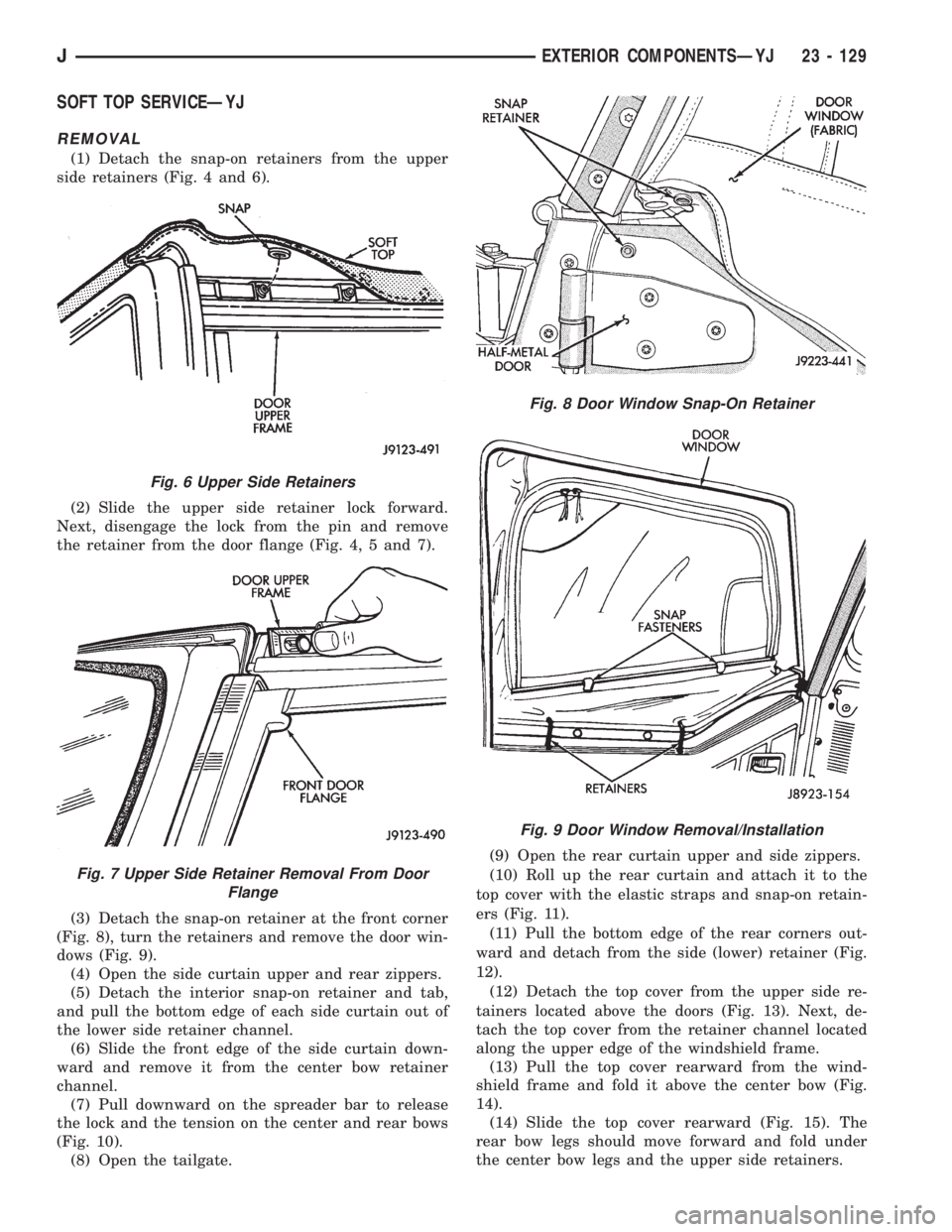
(1) Detach the snap-on retainers from the upper
side retainers (Fig. 4 and 6).
(2) Slide the upper side retainer lock forward.
Next, disengage the lock from the pin and remove
the retainer from the door flange (Fig. 4, 5 and 7).
(3) Detach the snap-on retainer at the front corner
(Fig. 8), turn the retainers and remove the door win-
dows (Fig. 9).
(4) Open the side curtain upper and rear zippers.
(5) Detach the interior snap-on retainer and tab,
and pull the bottom edge of each side curtain out of
the lower side retainer channel.
(6) Slide the front edge of the side curtain down-
ward and remove it from the center bow retainer
channel.
(7) Pull downward on the spreader bar to release
the lock and the tension on the center and rear bows
(Fig. 10).
(8) Open the tailgate.(9) Open the rear curtain upper and side zippers.
(10) Roll up the rear curtain and attach it to the
top cover with the elastic straps and snap-on retain-
ers (Fig. 11).
(11) Pull the bottom edge of the rear corners out-
ward and detach from the side (lower) retainer (Fig.
12).
(12) Detach the top cover from the upper side re-
tainers located above the doors (Fig. 13). Next, de-
tach the top cover from the retainer channel located
along the upper edge of the windshield frame.
(13) Pull the top cover rearward from the wind-
shield frame and fold it above the center bow (Fig.
14).
(14) Slide the top cover rearward (Fig. 15). The
rear bow legs should move forward and fold under
the center bow legs and the upper side retainers.
Fig. 6 Upper Side Retainers
Fig. 7 Upper Side Retainer Removal From Door
Flange
Fig. 8 Door Window Snap-On Retainer
Fig. 9 Door Window Removal/Installation
JEXTERIOR COMPONENTSÐYJ 23 - 129
Page 2052 of 2158
DOORS
INDEX
page page
Beltline SealÐYJ........................ 142
Door Frame Glass Channel ReplacementÐYJ . . . 142
Door Weatherstrip Seal ReplacementÐYJ...... 142
Full-Metal Door Assist HandleÐYJ........... 136
Full-Metal Door HingesÐYJ................ 140
Full-Metal Door Key Lock CylinderÐYJ........ 139
Full-Metal Door Latch External Release
HandleÐYJ........................... 140
Full-Metal Door Latch Inside Release and Lock
HandleÐYJ........................... 137
Full-Metal Door LatchÐYJ.................. 140Full-Metal Door ServiceÐYJ................ 142
Full-Metal Door Trim PanelÐYJ.............. 137
Full-Metal Door Vent Window GlassÐYJ....... 137
Full-Metal Door WaterdamÐYJ.............. 137
Full-Metal Door Weatherstrip SealsÐYJ........ 141
Full-Metal Door Window Glass Regulator
HandleÐYJ........................... 136
Full-Metal Door Window Glass RegulatorÐYJ . . . 138
Full-Metal Door Window GlassÐYJ........... 139
Half-Metal Door Latch StrikerÐYJ............ 135
Half-Metal Soft Top DoorÐYJ............... 134
HALF-METAL SOFT TOP DOORÐYJ
REMOVAL/DISASSEMBLY
(1) Open the door.
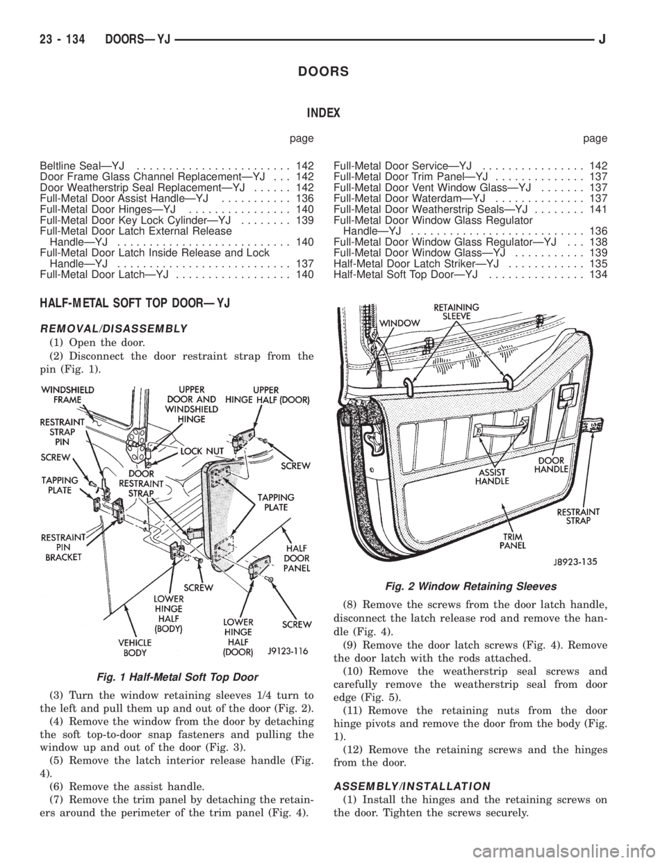
(2) Disconnect the door restraint strap from the
pin (Fig. 1).
(3) Turn the window retaining sleeves 1/4 turn to
the left and pull them up and out of the door (Fig. 2).
(4) Remove the window from the door by detaching
the soft top-to-door snap fasteners and pulling the
window up and out of the door (Fig. 3).
(5) Remove the latch interior release handle (Fig.
4).
(6) Remove the assist handle.
(7) Remove the trim panel by detaching the retain-
ers around the perimeter of the trim panel (Fig. 4).(8) Remove the screws from the door latch handle,
disconnect the latch release rod and remove the han-
dle (Fig. 4).
(9) Remove the door latch screws (Fig. 4). Remove
the door latch with the rods attached.
(10) Remove the weatherstrip seal screws and
carefully remove the weatherstrip seal from door
edge (Fig. 5).
(11) Remove the retaining nuts from the door
hinge pivots and remove the door from the body (Fig.
1).
(12) Remove the retaining screws and the hinges
from the door.
ASSEMBLY/INSTALLATION
(1) Install the hinges and the retaining screws on
the door. Tighten the screws securely.
Fig. 1 Half-Metal Soft Top Door
Fig. 2 Window Retaining Sleeves
23 - 134 DOORSÐYJJ
Page 2060 of 2158
DOOR WEATHERSTRIP SEAL REPLACEMENTÐYJ
REMOVAL
(1) Carefully remove the weatherstrip seal from
the door with a weatherstrip seal removal tool. Pry
the seal outward to separate the plastic retainers
from the door panel holes.
(2) Remove the upper portion of the seal from the
door upper frame with your fingers or a wooden
wand.
(3) Remove the dust and residual adhesive from
the door panel and body panel.
INSTALLATION
(1) Apply adhesive to the front, rear and bottom
edges of the door from the beltline downward.
(2) Install the upper front corner of the seal on the
door first using your fingers or a wooden wand to po-
sition the seal in the channel. Place the inner shoul-
der of the seal in the channel-to-window frame above
the beltline.
(3) Force the retainers, starting at the rear edge of
the door, into the door panel holes.
(4) Ensure that the seal is completely seated
around the door.
BELTLINE SEALÐYJ
REMOVAL
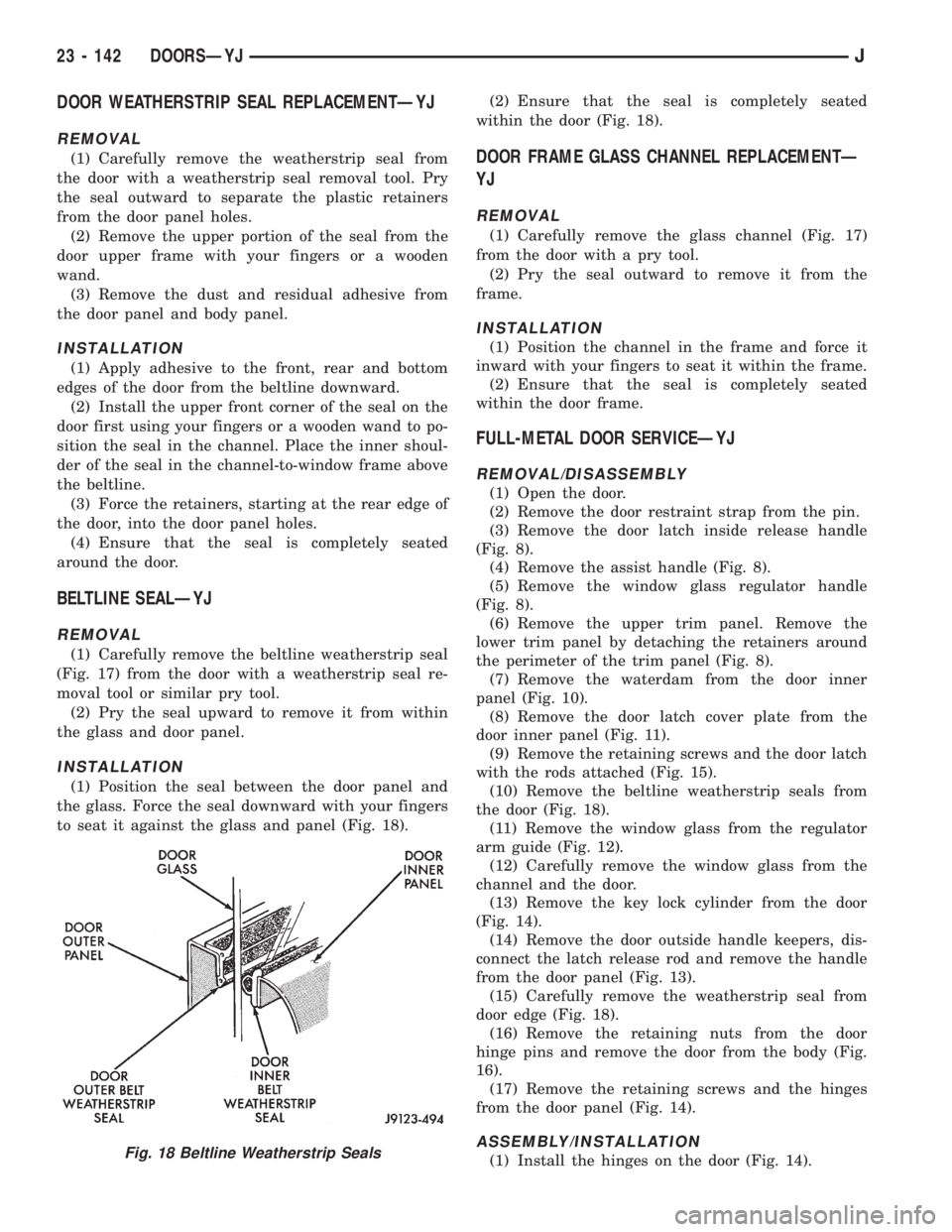
(1) Carefully remove the beltline weatherstrip seal
(Fig. 17) from the door with a weatherstrip seal re-
moval tool or similar pry tool.
(2) Pry the seal upward to remove it from within
the glass and door panel.
INSTALLATION
(1) Position the seal between the door panel and
the glass. Force the seal downward with your fingers
to seat it against the glass and panel (Fig. 18).(2) Ensure that the seal is completely seated
within the door (Fig. 18).
DOOR FRAME GLASS CHANNEL REPLACEMENTÐ
YJ
REMOVAL
(1) Carefully remove the glass channel (Fig. 17)
from the door with a pry tool.
(2) Pry the seal outward to remove it from the
frame.
INSTALLATION
(1) Position the channel in the frame and force it
inward with your fingers to seat it within the frame.
(2) Ensure that the seal is completely seated
within the door frame.
FULL-METAL DOOR SERVICEÐYJ
REMOVAL/DISASSEMBLY
(1) Open the door.
(2) Remove the door restraint strap from the pin.
(3) Remove the door latch inside release handle
(Fig. 8).
(4) Remove the assist handle (Fig. 8).
(5) Remove the window glass regulator handle
(Fig. 8).
(6) Remove the upper trim panel. Remove the
lower trim panel by detaching the retainers around
the perimeter of the trim panel (Fig. 8).
(7) Remove the waterdam from the door inner
panel (Fig. 10).
(8) Remove the door latch cover plate from the
door inner panel (Fig. 11).
(9) Remove the retaining screws and the door latch
with the rods attached (Fig. 15).
(10) Remove the beltline weatherstrip seals from
the door (Fig. 18).
(11) Remove the window glass from the regulator
arm guide (Fig. 12).
(12) Carefully remove the window glass from the
channel and the door.
(13) Remove the key lock cylinder from the door
(Fig. 14).
(14) Remove the door outside handle keepers, dis-
connect the latch release rod and remove the handle
from the door panel (Fig. 13).
(15) Carefully remove the weatherstrip seal from
door edge (Fig. 18).
(16) Remove the retaining nuts from the door
hinge pins and remove the door from the body (Fig.
16).
(17) Remove the retaining screws and the hinges
from the door panel (Fig. 14).
ASSEMBLY/INSTALLATION
(1) Install the hinges on the door (Fig. 14).Fig. 18 Beltline Weatherstrip Seals
23 - 142 DOORSÐYJJ
Page 2063 of 2158
²Apply one drop of adhesive at the center of the re-
taining bracket contact surface on the windshield
glass.
²Immediately apply an even coat of adhesive to the
contact surface on the retaining bracket.
²Align the retaining bracket with the position refer-
ence lines on the windshield glass.
²Press and hold the retaining bracket in-place for
at least one minute.
Ensure that the mirror retaining bracket is
correctly aligned because the adhesive will
cure rapidly.
(8) Allow the adhesive to cure for 8-10 minutes,
then remove any residue adhesive with an alcohol
dampened cloth.
(9) Allow the adhesive to cure for an additional
8-10 minutes before installing the mirror on the re-
taining bracket (Fig. 1).
WINDSHIELD FRAMEÐYJ
SERVICE INFORMATION
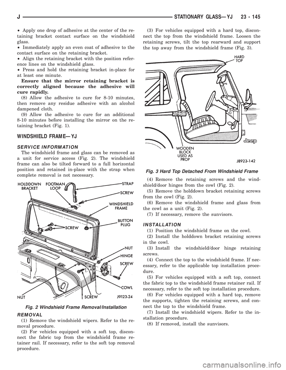
The windshield frame and glass can be removed as
a unit for service access (Fig. 2). The windshield
frame can also be tilted forward to a full horizontal
position and retained in-place with the strap when
complete removal is not necessary.
REMOVAL
(1) Remove the windshield wipers. Refer to the re-
moval procedure.
(2) For vehicles equipped with a soft top, discon-
nect the fabric top from the windshield frame re-
tainer rail. If necessary, refer to the soft top removal
procedure.(3) For vehicles equipped with a hard top, discon-
nect the top from the windshield frame. Loosen the
retaining screws, tilt the top rearward and support
the top away from the windshield frame (Fig. 3).
(4) Remove the retaining screws and the wind-
shield/door hinges from the cowl (Fig. 2).
(5) Remove the holddown bracket retaining screws
from the cowl (Fig. 2).
(6) Remove the windshield frame and glass from
the cowl as a unit (Fig. 2).
(7) If necessary, remove the sunvisors.
INSTALLATION
(1) Position the windshield frame on the cowl.
(2) Install the holddown bracket retaining screws
in the cowl.
(3) Install the windshield/door hinge retaining
screws.
(4) Connect the top to the windshield frame. If nec-
essary, refer to the applicable top installation proce-
dure.
(5) For vehicles equipped with a soft top, connect
the fabric top to the windshield frame retainer rail. If
necessary, refer to the soft top installation procedure.
(6) For vehicles equipped with a hard top, remove
the supports, tighten the retaining screws, and con-
nect the top to the windshield frame.
(7) Install the windshield wipers. Refer to the in-
stallation procedure.
(8) If removed, install the sunvisors.
Fig. 2 Windshield Frame Removal/Installation
Fig. 3 Hard Top Detached From Windshield Frame
JSTATIONARY GLASSÐYJ 23 - 145
Page 2070 of 2158
(2) Install the bezel screws. Tighten the screws to
3Nzm (24 in-lbs) torque.
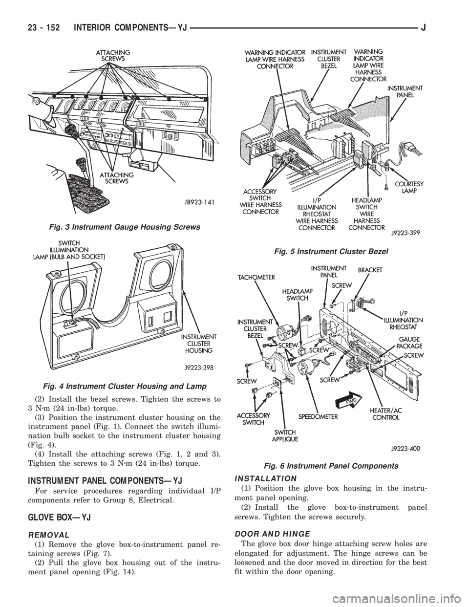
(3) Position the instrument cluster housing on the
instrument panel (Fig. 1). Connect the switch illumi-
nation bulb socket to the instrument cluster housing
(Fig. 4).
(4) Install the attaching screws (Fig. 1, 2 and 3).
Tighten the screws to 3 Nzm (24 in-lbs) torque.
INSTRUMENT PANEL COMPONENTSÐYJ
For service procedures regarding individual I/P
components refer to Group 8, Electrical.
GLOVE BOXÐYJ
REMOVAL
(1) Remove the glove box-to-instrument panel re-
taining screws (Fig. 7).
(2) Pull the glove box housing out of the instru-
ment panel opening (Fig. 14).
INSTALLATION
(1) Position the glove box housing in the instru-
ment panel opening.
(2) Install the glove box-to-instrument panel
screws. Tighten the screws securely.
DOOR AND HINGE
The glove box door hinge attaching screw holes are
elongated for adjustment. The hinge screws can be
loosened and the door moved in direction for the best
fit within the door opening.
Fig. 3 Instrument Gauge Housing Screws
Fig. 4 Instrument Cluster Housing and Lamp
Fig. 5 Instrument Cluster Bezel
Fig. 6 Instrument Panel Components
23 - 152 INTERIOR COMPONENTSÐYJJ