1995 JEEP YJ service
[x] Cancel search: servicePage 1948 of 2158
DOORS
INDEX
page page
Door Alignment AdjustmentÐMajor............ 41
Door Alignment AdjustmentÐMinor............ 37
Door Edge Guard/Edge Protector StripÐXJ...... 54
Door External HandleÐXJ................... 48
Door Hinge/Hinge Pin ReplacementÐXJ........ 52
Door Inside Latch Release and Lock RodsÐXJ . . . 50
Door Key Lock CylinderÐXJ................. 47
Door Latch AdjustmentÐXJ.................. 48
Door LatchÐXJ.......................... 49
Door Removal/InstallationÐXJ............... 35
Door Restraint ReplacementÐXJ............. 41
Door Trim PanelÐXJ...................... 31
Door Window Exterior MoldingsÐXJ........... 54
Door Window Glass and Door Opening
Weatherstrip SealsÐXJ................... 55
Front Door Spacer BlocksÐTwo-Door Vehicles . . . 53
Front Door Window Glass RegulatorÐXJ........ 42Front Door Window GlassÐXJ............... 43
Liftgate AdjustmentÐXJ.................... 63
Liftgate HingeÐXJ........................ 60
Liftgate Latch/Key Lock Cylinder/StrikerÐXJ..... 61
Liftgate License Plate Lamp HousingÐXJ....... 65
Liftgate License Plate Screw Anchor and BumperÐXJ.65
Liftgate Opening Weatherstrip SealÐXJ........ 64
Liftgate Support Rod Ball Stud ReplacementÐXJ . 63
Liftgate Support Rod Cylinder DisposalÐXJ...... 63
Liftgate Support Rod CylinderÐXJ............. 62
Liftgate Trim PanelÐXJ..................... 59
LiftgateÐXJ............................. 58
Rear Door Stationary Window GlassÐXJ........ 46
Rear Door Window Glass RegulatorÐXJ........ 44
Rear Door Window GlassÐXJ................ 45
Service Information........................ 30
SERVICE INFORMATION
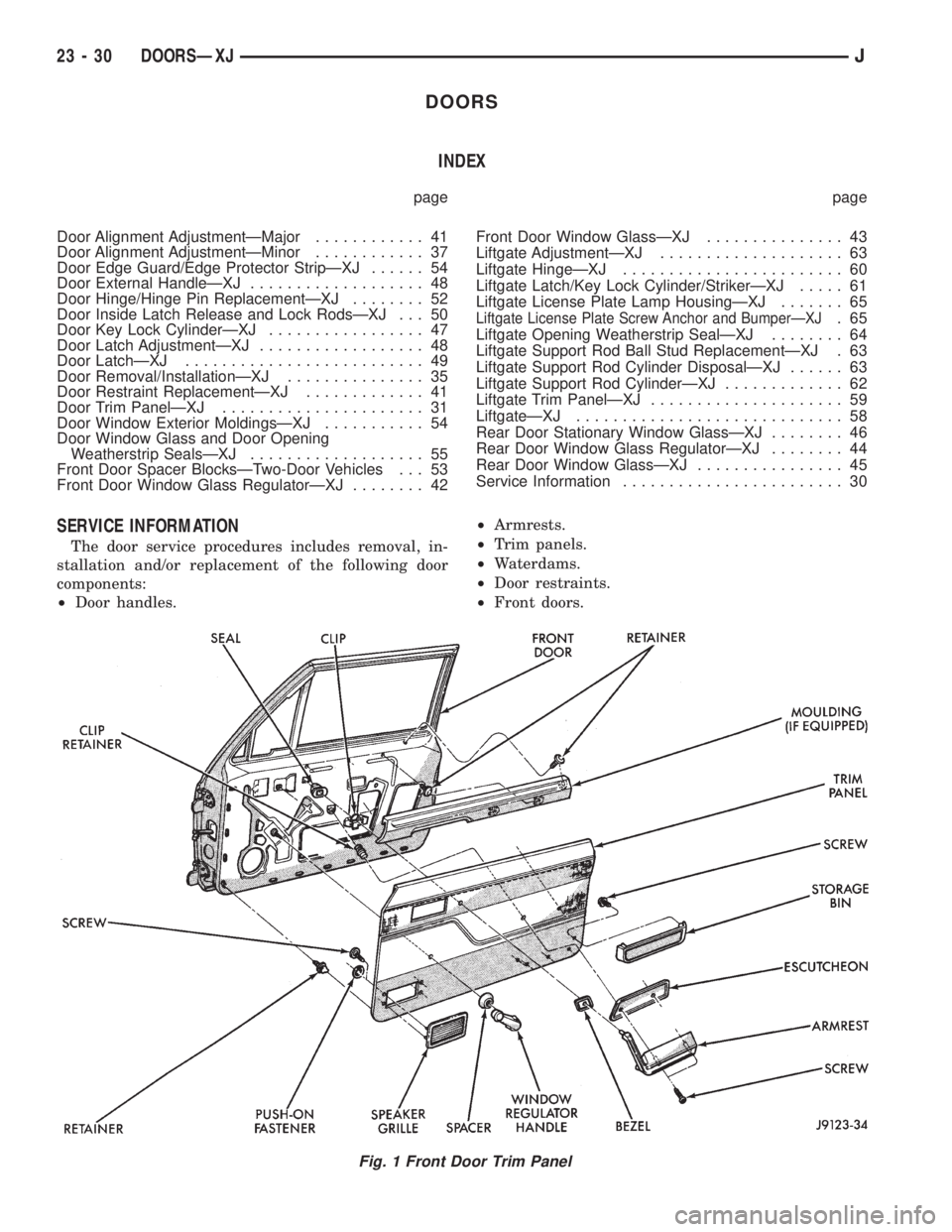
The door service procedures includes removal, in-
stallation and/or replacement of the following door
components:
²Door handles.²Armrests.
²Trim panels.
²Waterdams.
²Door restraints.
²Front doors.
Fig. 1 Front Door Trim Panel
23 - 30 DOORSÐXJJ
Page 1949 of 2158
²Rear doors.
²Window glass regulators.
²Key lock cylinders.
²Door half-hinges.
²Liftgate.
²Liftgate hinges.
²Liftgate gas support rod cylinders.
²Rocker panel seals.
²Moldings/weatherstrip seals.DOOR TRIM PANELÐXJ
SERVICE INFORMATION
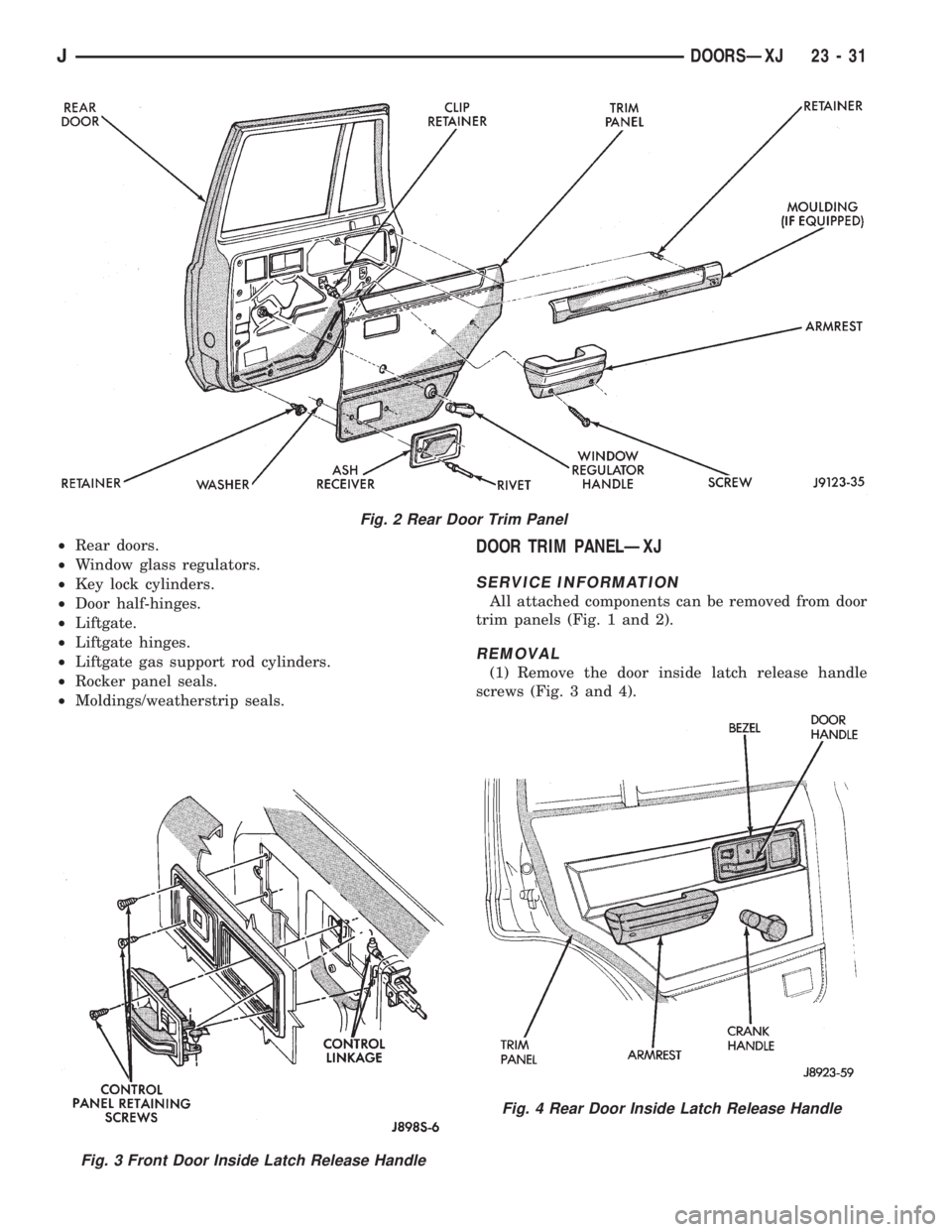
All attached components can be removed from door
trim panels (Fig. 1 and 2).
REMOVAL
(1) Remove the door inside latch release handle
screws (Fig. 3 and 4).
Fig. 2 Rear Door Trim Panel
Fig. 3 Front Door Inside Latch Release Handle
Fig. 4 Rear Door Inside Latch Release Handle
JDOORSÐXJ 23 - 31
Page 1981 of 2158
LIFTGATE SUPPORT ROD CYLINDER DISPOSALÐ
XJ
WARNING: SAFETY GOGGLES MUST BE WORN
DURING THE DISPOSAL PROCEDURE. THE HIGH
PRESSURE GAS CHARGE IN THE SUPPORT ROD
CYLINDERS WILL BE RELEASED DURING THE
PROCEDURE.
(1) Remove the support rod cylinder(s) from the
liftgate.
(2) Position the support rod cylinder horizontally
in a vise and clamp the cylinder securely.
(3) Wrap the cylinder with 4-5 layers of shop tow-
els.
(4) Measure 1 and 1/2 inches inward from the end
of the cylinder. Mark this location on the towels with
chalk. The cylinder will be punctured at this location
to release the gas charge.
(5) Use a punch and hammer to puncture cylinder.
Force the punch through towels and into the cylinder
with a hammer. Continue striking the punch until
the gas begins to escapebut do not remove the
punch.
(6) Hold the towels and punch in position until all
the gas has escaped. Complete de-pressurization will
require about 4 to 10 seconds. After all the gas has
escaped, slowly remove the punch.
(7) Hold a towel over the hole in cylinder and press
the support rod piston all the way into the cylinder
to purge remaining oil.
(8) Remove the support rod cylinder from the vise
and discard it.
(9) If both support rod cylinders are being re-
placed, repeat this procedure for the remaining cylin-
der.
LIFTGATE SUPPORT ROD BALL STUD
REPLACEMENTÐXJ
REMOVAL
(1) Open the liftgate.
(2) Support the liftgate in the open position.
(3) Remove the retainer clip that attaches the sup-
port rod and cylinder to the ball stud.
(4) Disconnect the support rod from the ball stud.
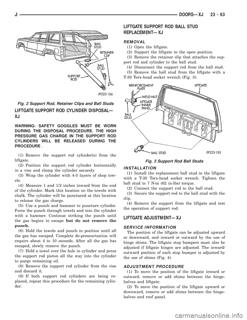
(5) Remove the ball stud from the liftgate with a
T-30 Torx-head socket wrench (Fig. 3).
INSTALLATION
(1) Install the replacement ball stud in the liftgate
with a T-30 Torx-head socket wrench. Tighten the
ball stud to 7 Nzm (62 in-lbs) torque.
(2) Connect the support rod to the ball stud.
(3) Secure the support rod to the ball stud with the
clip.
(4) Remove the support from the liftgate and test
the operation of support rod.
LIFTGATE ADJUSTMENTÐXJ
SERVICE INFORMATION
The position of the liftgate can be adjusted upward
or downward, and inward or outward by the use of
hinge shims. The liftgate stop bumpers must also be
adjusted if liftgate hinges are adjusted. The inward/
outward position of each stop bumper is adjusted by
the use of shims (Fig. 4).
ADJUSTMENT PROCEDURE
(1) To move the position of the liftgate inward or
outward, remove or add shims between the hinge-
halves and liftgate.
(2) To move the position of the liftgate upward or
downward, remove or add shims between the hinge-
halves and roof panel.
Fig. 2 Support Rod, Retainer Clips and Ball Studs
Fig. 3 Support Rod Ball Studs
JDOORSÐXJ 23 - 63
Page 1994 of 2158
STATIONARY GLASS WATER LEAK DETECTION
AND REPAIRÐXJ
SERVICE INFORMATION
Water leaks around the windshield or a stationary
window glass can be sealed without removing the
glass. If the windshield/window glass is bonded and
only has a small leak, seal it with a liquid butyl seal-
ant. If the weatherstrip seal or urethane adhesive
has a large break, a urethane adhesive must be used
to seal the leak.
LEAK TEST
Water test the windshield/window with a spray
only.Do not use hard streams of water.Work from
the bottom to the top of windshield/window glass.
If a water leak exists between the glass and weath-
erstrip seal (or between the seal and a body flange):
²Push the glass outward at the leak area, and de-
termine the extent of the gap.
Push the glass outward while a helper sprays the
windshield/window with water.
SEALING MINOR LEAK AREAS
(1) Thoroughly clean and remove all foreign mate-
rial from the leak area. Dry area with compressed
air.
(2) Seal the leak area with butyl sealant. Allow the
sealant to cure for at least 1/2 hour. Next, water test
the glass to ensure that the leak is sealed.
SEALING MAJOR LEAK AREAS
(1) Thoroughly clean the leak area.
(2) As applicable, apply primer to either the wind-
shield/window or weatherstrip seal leak area. Use
blackout primer on the windshield/window and ure-
thane primer on the weatherstrip seal.
(3) Apply urethane adhesive to the leak area. Use
an adhesive cartridge with a pointed nozzle.
(4) Water test the windshield/window immediately
with cold water spray. Allow water to spill over the
edge of the windshield/window and weatherstrip seal.
Do not direct a hard stream of water on re-
cently applied urethane.
(5) Apply additional urethane adhesive, if neces-
sary.
(6) Remove any excess urethane adhesive.
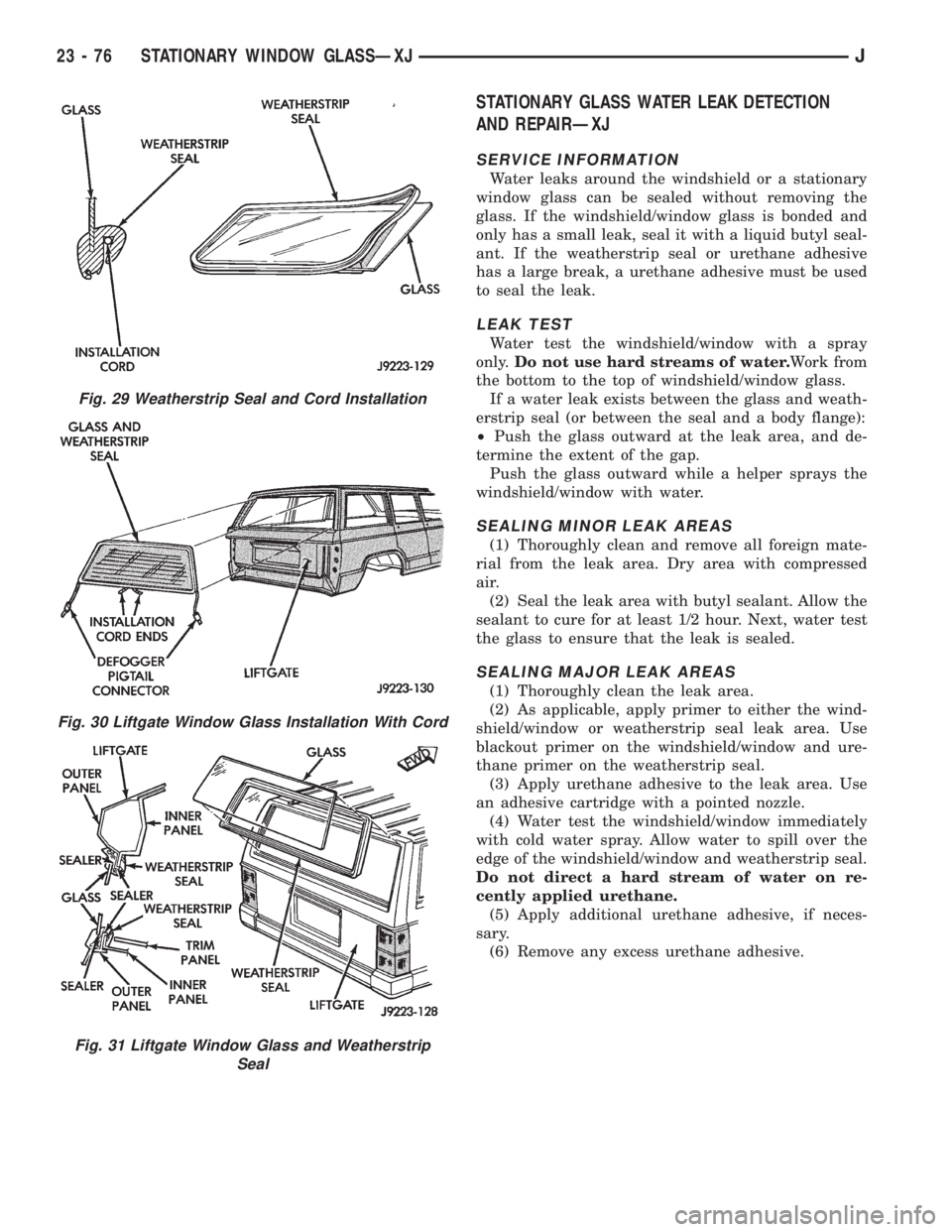
Fig. 29 Weatherstrip Seal and Cord Installation
Fig. 30 Liftgate Window Glass Installation With Cord
Fig. 31 Liftgate Window Glass and Weatherstrip
Seal
23 - 76 STATIONARY WINDOW GLASSÐXJJ
Page 1998 of 2158
INTERIOR COMPONENTS
INDEX
page page
Assist HandleÐXJ........................ 89
B/C-Pillar and Liftgate Pillar Trim CoversÐXJ.... 88
Bucket Seat Cushion and CoverÐXJ........... 81
Bucket Seat PlatformÐXJ................... 82
Bucket Seatback Cover and FrameÐXJ........ 81
Cargo BarrierÐXJ........................ 101
Cargo LampÐXJ......................... 94
Carpets and Floor MatsÐXJ................. 99
Dome LampÐXJ......................... 93
Front Bucket SeatsÐXJ.................... 81
Front Carpet/MatÐXJ...................... 99
Front Inner Scuff Plate/Cowl Side Trim PanelÐXJ . 86
Front Shoulder Belt/BuckleÐXJ............... 90
Full Floor ConsoleÐXJ..................... 95
HeadlinerÐXJ............................ 92
I/P Ash Receiver Tray LampÐXJ.............. 80
Instrument Cluster BezelÐXJ................ 80
Interior Trim Panels and Scuff PlatesÐXJ....... 84
Jack StorageÐXJ......................... 97
Keyless Entry ReceiverÐXJ................. 93Mini-Console with Floor ShiftÐXJ............. 94
Mini-Floor ConsoleÐXJ..................... 94
Outer Scuff PlatesÐXJ..................... 89
Overhead ConsoleÐXJ..................... 93
Parking Brake Handle CoverÐXJ............. 94
Quarter and Wheelhouse Trim PanelsÐXJ...... 87
Quarter Trim Panel ExtensionÐXJ............. 87
Rear Carpet/MatÐXJ..................... 100
Rear Seat Cushion CoverÐXJ............... 82
Rear Seat CushionÐXJ.................... 82
Rear Seatback CoverÐXJ................... 84
Rear Seatback Latch Striker and BumperÐXJ.... 84
Rear SeatbackÐXJ........................ 83
Rear Shoulder/Lap Belt/BuckleÐXJ............ 91
Sound BarÐXJ........................... 94
Spare Tire/Wheel Holddown and Floor
BracketsÐXJ........................... 98
SunvisorsÐXJ........................... 93
Windshield Side MoldingÐXJ................ 86
INSTRUMENT CLUSTER BEZELÐXJ
REMOVAL
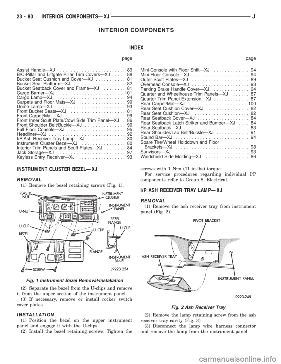
(1) Remove the bezel retaining screws (Fig. 1).
(2) Separate the bezel from the U-clips and remove
it from the upper section of the instrument panel.
(3) If necessary, remove or install rocker switch
cover plates.
INSTALLATION
(1) Position the bezel on the upper instrument
panel and engage it with the U-clips.
(2) Install the bezel retaining screws. Tighten thescrews with 1 Nzm (11 in-lbs) torque.
For service procedures regarding individual I/P
components refer to Group 8, Electrical.
I/P ASH RECEIVER TRAY LAMPÐXJ
REMOVAL
(1) Remove the ash receiver tray from instrument
panel (Fig. 2).
(2) Remove the lamp retaining screw from the ash
receiver tray cavity (Fig. 3).
(3) Disconnect the lamp wire harness connector
and remove the lamp from the instrument panel.
Fig. 1 Instrument Bezel Removal/Installation
Fig. 2 Ash Receiver Tray
23 - 80 INTERIOR COMPONENTSÐXJJ
Page 2020 of 2158
BODY COMPONENTSÐYJ VEHICLES
CONTENTS
page page
DOORS............................... 134
EXTERIOR COMPONENTS................ 104
GENERAL SERVICE INFORMATION......... 102INTERIOR COMPONENTS................ 151
PAINT................................ 158
STATIONARY GLASS.................... 144
GENERAL SERVICE INFORMATION
LABELS/DECALS/PLATESÐYJ
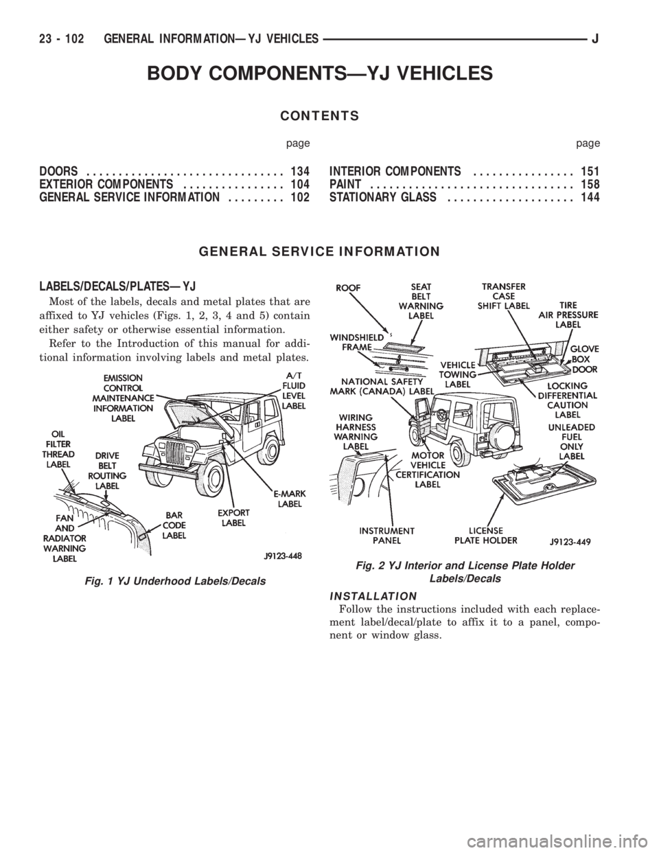
Most of the labels, decals and metal plates that are
affixed to YJ vehicles (Figs. 1, 2, 3, 4 and 5) contain
either safety or otherwise essential information.
Refer to the Introduction of this manual for addi-
tional information involving labels and metal plates.
INSTALLATION
Follow the instructions included with each replace-
ment label/decal/plate to affix it to a panel, compo-
nent or window glass.
Fig. 1 YJ Underhood Labels/Decals
Fig. 2 YJ Interior and License Plate Holder
Labels/Decals
23 - 102 GENERAL INFORMATIONÐYJ VEHICLESJ
Page 2022 of 2158
EXTERIOR COMPONENTS
INDEX
page page
Battery TrayÐYJ......................... 110
Body Side Step MoldingÐYJ................ 115
Body Stripes/DecalsÐYJ................... 116
Cowl Grille and ScreenÐYJ................ 109
Cowl Weatherstrip SealÐYJ................ 109
Exterior Nameplates (Adhesive-Backed)ÐYJ.... 120
External Spare/Wheel Tire CarrierÐYJ........ 133
Fender FlareÐYJ........................ 114
Fender Inner Splash ShieldsÐYJ............. 116
Fender Splash ApronsÐYJ................. 115
FendersÐYJ............................ 110
Fuel Filler Protector/NozzleÐYJ............. 121
Half Metal Door Mirror (External)ÐYJ......... 121
Hard Top Liftgate GlassÐYJ................ 124
Hard Top RepairÐYJ..................... 127
Hard Top Roof VentÐYJ................... 127
Hard TopÐYJ........................... 126Hood AlignmentÐYJ...................... 107
Hood Insulator PanelÐYJ.................. 107
Hood Safety LatchÐYJ.................... 109
HoodÐYJ.............................. 107
Liftgate Glass Weatherstrip Seal ReplacementÐYJ. 125
Radiator Grille AppliqueÐYJ................ 104
Soft Top Service InformationÐYJ............. 127
Soft Top ServiceÐYJ..................... 129
Sport BarÐYJ........................... 132
Tailgate AdjustmentÐYJ................... 121
Tailgate HingeÐYJ....................... 121
Tailgate Latch and Release HandleÐYJ........ 122
Tailgate Latch StrikerÐYJ.................. 123
Tailgate Lock CylinderÐYJ................. 122
Tailgate Weatherstrip SealÐYJ.............. 123
TailgateÐYJ............................ 121
Wheelhouse Splash LinersÐYJ.............. 115
RADIATOR GRILLE APPLIQUEÐYJ
REMOVAL
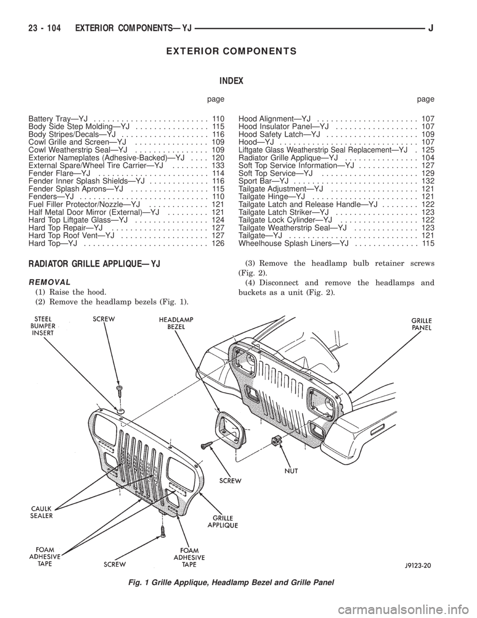
(1) Raise the hood.
(2) Remove the headlamp bezels (Fig. 1).(3) Remove the headlamp bulb retainer screws
(Fig. 2).
(4) Disconnect and remove the headlamps and
buckets as a unit (Fig. 2).
Fig. 1 Grille Applique, Headlamp Bezel and Grille Panel
23 - 104 EXTERIOR COMPONENTSÐYJJ
Page 2028 of 2158
BATTERY TRAYÐYJ
REMOVAL
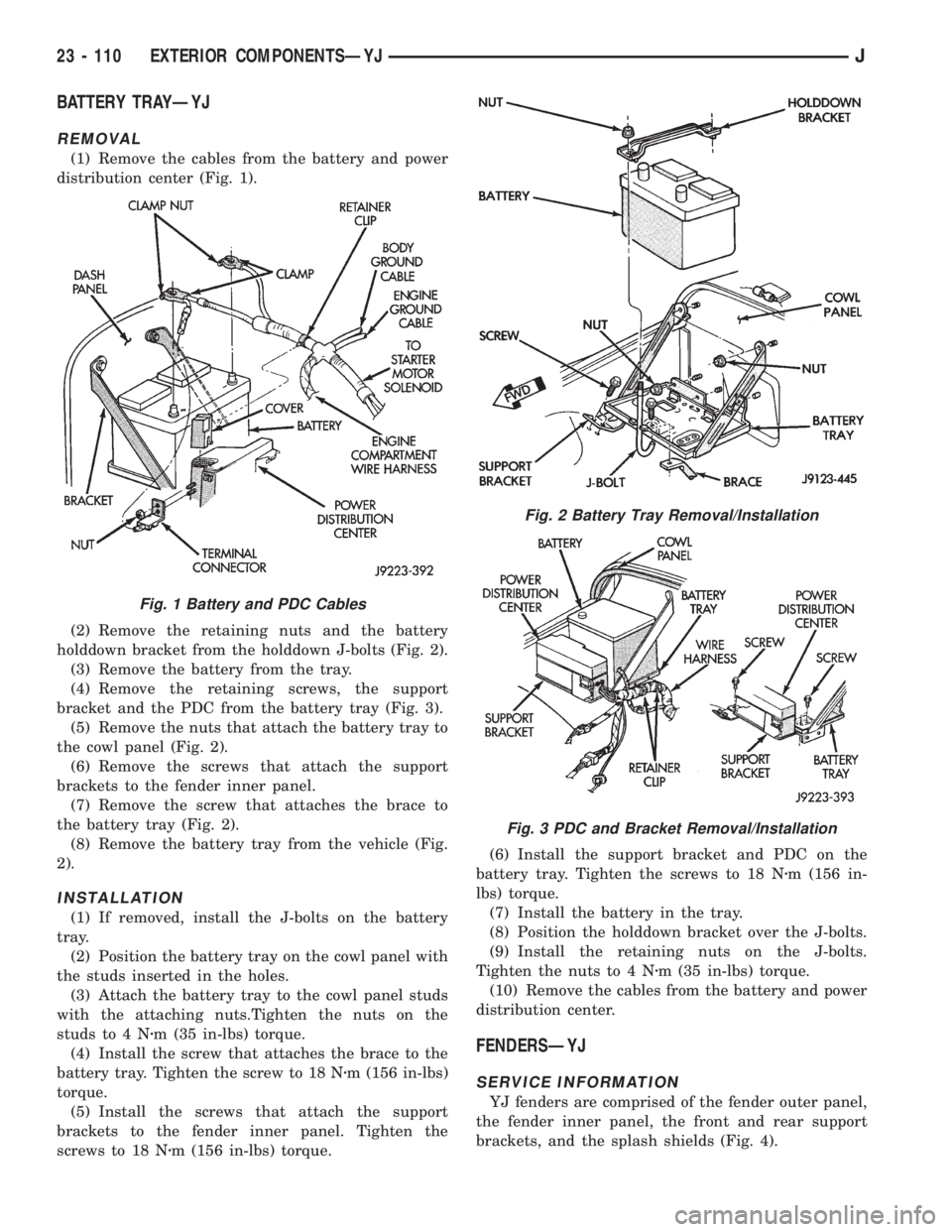
(1) Remove the cables from the battery and power
distribution center (Fig. 1).
(2) Remove the retaining nuts and the battery
holddown bracket from the holddown J-bolts (Fig. 2).
(3) Remove the battery from the tray.
(4) Remove the retaining screws, the support
bracket and the PDC from the battery tray (Fig. 3).
(5) Remove the nuts that attach the battery tray to
the cowl panel (Fig. 2).
(6) Remove the screws that attach the support
brackets to the fender inner panel.
(7) Remove the screw that attaches the brace to
the battery tray (Fig. 2).
(8) Remove the battery tray from the vehicle (Fig.
2).
INSTALLATION
(1) If removed, install the J-bolts on the battery
tray.
(2) Position the battery tray on the cowl panel with
the studs inserted in the holes.
(3) Attach the battery tray to the cowl panel studs
with the attaching nuts.Tighten the nuts on the
studs to 4 Nzm (35 in-lbs) torque.
(4) Install the screw that attaches the brace to the
battery tray. Tighten the screw to 18 Nzm (156 in-lbs)
torque.
(5) Install the screws that attach the support
brackets to the fender inner panel. Tighten the
screws to 18 Nzm (156 in-lbs) torque.(6) Install the support bracket and PDC on the
battery tray. Tighten the screws to 18 Nzm (156 in-
lbs) torque.
(7) Install the battery in the tray.
(8) Position the holddown bracket over the J-bolts.
(9) Install the retaining nuts on the J-bolts.
Tighten the nuts to 4 Nzm (35 in-lbs) torque.
(10) Remove the cables from the battery and power
distribution center.
FENDERSÐYJ
SERVICE INFORMATION
YJ fenders are comprised of the fender outer panel,
the fender inner panel, the front and rear support
brackets, and the splash shields (Fig. 4).
Fig. 1 Battery and PDC Cables
Fig. 2 Battery Tray Removal/Installation
Fig. 3 PDC and Bracket Removal/Installation
23 - 110 EXTERIOR COMPONENTSÐYJJ