1995 JEEP YJ service
[x] Cancel search: servicePage 2096 of 2158
off switch for battery voltage. If no voltage is present
test pressure cut-off switch. If voltage is present go
to next step.
(5) With ohmmeter test harness connector ground
circuit for continuity to ground. If circuit is open, (no
continuity) repair ground circuit. If circuit test OK
and clutch does not engage refer to Powertrain Diag-
nostic Service Manual for A/C clutch circuit test.
AIR CONDITIONING CONTROLSÐYJ VEHICLES
The air conditioning circuit consists of 3 segments;
battery supply, blower motor and compressor clutch.
The 3 segments have a common connection point at
the blower switch.
The power supply circuit extends from the HTR/
FAN fuse to the blower switch. From the blower
switch, battery feed is routed to the blower motor
and compressor clutch circuit.
Refer to Group 8W Wiring Diagrams for wiring
schematic and terminals. Use volt ohmmeter to test
switches.
COMPRESSOR CLUTCH
The clutch assembly consists of a stationary elec-
tromagnetic coil, hub bearing pulley assembly, and
clutch plate. When the coil is energized the plate is
magnetically engaged with the pulley and turns the
compressor shaft.
COMPRESSOR CLUTCH TEST
(1) Unplug clutch coil connector.
(2) Connect jumper wire from battery positive post
to clutch coil connector. The clutch should engage, if
not leave jumper wire connected and go to next step.
(3) Connect jumper wire from clutch coil frame to
chassis ground. The clutch should engage, if not re-
pair clutch coil ground or replace coil.
A/C COMPRESSOR CLUTCH RELAY
The A/C compressor clutch relay controls the 12-
volt source to the A/C clutch. The relay is activated
when the PCM receives a A/C request signal. The
PCM then sends a ground signal to the relay. The re-
lay is activated and sends 12-volts to the clutch coil
which energizes the clutch. The relay is located in
the power distribution center.
COMPRESSOR CLUTCH RELAY TEST
For test procedure refer to Powertrain Diagnostic
Service Manual for A/C clutch relay circuit test.
LOW-PRESSURE HIGH-PRESSURE CUT-OFF
SWITCH
The pressure cut-off switch is located on the filter
drier and is wired in series with compressor clutch.
The switch interrupts the power to the compressorclutch circuit when the pressure drops to 193 kPa (28
psi) or increases above 3100 to 3375 kPa (450 to 490
psi).
PRESSURE CUT-OFF SWITCH TEST
(1) Turn ignition switch to RUN, A/C blower switch
to ON and control set to MAX.
(2) Unplug pressure cut-off switch connector and
test feed circuit from the thermostatic, should be bat-
tery voltage. If not, proceed to thermostatic control
tests.
(3) Test for continuity between the switch termi-
nals. If continuity is not present recover refrigerant
system, replace switch, evacuate and recharge sys-
tem.
THERMOSTATIC CONTROL
Cycling of the compressor and therefore the tem-
perature of the outlet air is regulated by the thermo-
static control. A thermal sensor extends from the
control to the evaporator housing. When the temper-
ature of the evaporator drops below the set tempera-
ture, the thermostatic control opens the clutch
circuit. The circuit remains open until evaporator
temperature rises above the set temperature.
THERMOSTATIC CONTROL TEST
(1) Turn ignition switch to RUN, A/C blower switch
to ON and thermostatic control set to MAX cool.
(2) Test thermostatic control feed terminal from
blower switch, should be battery voltage. If not re-
pair open from blower switch.
(3) Test thermostatic control output terminal to
pressure cut-out switch, should be battery voltage. If
not, replace thermostatic control.
BLOWER MOTOR SWITCH
The blower switch controls blower motor speed.
The blower motor segment consists of the 3 wires
from the blower switch to the motor. Through the
switch, the 3 wires connect the motor brushes to bat-
tery supply. When connected to battery feed, the sep-
arate brushes provide the 3 blower speeds LO, MED,
and HIGH.
BLOWER MOTOR SWITCH TEST
(1) Turn ignition to RUN position.
(2) Test battery side of fuse for battery voltage. If
not, repair open from ignition switch.
(3) Test A/C blower switch feed circuit from fuse
box should be battery voltage. If not, repair open
from fuse panel.
(4) Test A/C blower switch LO terminal with
blower switch in LO, should be battery voltage. If
not, replace switch.
(5) Test A/C blower switch MED terminal with
blower switch in MED, should be battery voltage. If
not, replace switch.
24 - 16 HEATING AND AIR CONDITIONINGJ
Page 2099 of 2158
COMPRESSOR SERVICE
DESCRIPTION
The A/C system uses a Sanden SD7H15 compres-
sor. The compressor is a 7 piston design.
The clutch used on the compressor consists of 3 ba-
sic components: the pulley and bearing hub, clutch
plate and field coil (Fig. 1). The pulley and field coil
are attached to the front of the compressor with ta-
pered snap rings. The compressor has a splined shaft
and the clutch plate is retained on the shaft with a
self-locking nut.
COMPRESSOR
REVIEW WARNINGS AND CAUTIONS IN
THIS GROUP BEFORE PROCEEDING WITH
THIS PROCEDURE.
REMOVAL
(1) Recover refrigerant from A/C system.
(2) Disconnect negative cable from battery.
(3) Disconnect the clutch lead wire.
(4) Remove the discharge and suction lines from
the compressor. Plug or tape all the openings.
(5) Remove the serpentine drive belt (refer to
Group 7, Cooling System for the proper procedure).
(6) Remove the bolts and lift the compressor from
the mounting bracket (Figs. 2 and 3).
INSTALLATION
If a replacement compressor is being in-
stalled; check the oil level. Add or subtract oil
as necessary and install the magnetic clutch on
the compressor.
(1) If the mounting bracket was removed, install
the bracket to the block. Tighten the mounting bolts
to 27 Nzm (20 ft. lbs.) torque.
(2) Install the compressor on the mounting
bracket. Tighten the bolts to 27 Nzm (20 ft. lbs.)
torque.(3) Install the serpentine drive belt (refer to Group
7, Cooling System for the proper procedure).
(4) Tighten the serpentine drive belt to the speci-
fied tension.
²New belt tensionÐ800-900 N (180-200 lb-f).
²Used belt tensionÐ623-712 N (140-160 lb-f).
(5) Remove the tape or plastic plugs from all the
suction and discharge openings and install lines on
the compressor.
(6) Connect the clutch lead wire.
(7) Connect negative cable to battery.
(8) Evacuate, charge and test the system for leaks.
Fig. 1 Compressor Clutch
Fig. 2 Compressor and Mounting Bracket (LH Drive
Vehicles)
Fig. 3 Compressor and Mounting Bracket (RH Drive
Vehicles)
JHEATING AND AIR CONDITIONING 24 - 19
Page 2100 of 2158
COMPRESSOR CLUTCH ASSEMBLY
The compressor clutch can be serviced in the vehi-
cle.
REMOVAL
(1) Remove the serpentine drive belt (refer to
Group 7, Cooling System for the proper procedure).
(2) Remove compressor mounting bolts and lift the
compressor from the mounting bracket. Support the
compressor to work on clutch.
(3) Insert the 2 pins of spanner C-4489 into holes
of the clutch plate. Hold clutch plate stationary and
remove hex nut (Fig. 4).
(4) Remove clutch plate with puller 6461 (Fig. 5).
(5) Remove key and clutch shims.
(6) Remove the external front housing snap ring
with snap ring pliers (Fig. 6).
(7) Install lip of rotor puller 6141-1 into the snap
ring groove exposed in the previous step and install
shaft protector 6141-2 (Fig. 7).(8) Install puller 6461 and through bolts into the
jaws finger tight (Fig. 8). Turn puller center bolt
clockwise until rotor pulley is free.
Fig. 6 External Snap Ring Removal
Fig. 7 Shaft Protector and Puller
Fig. 8 Install Puller Plate
Fig. 4 Hex Nut Removal
Fig. 5 Clutch Plate Puller
24 - 20 HEATING AND AIR CONDITIONINGJ
Page 2103 of 2158
COMPONENT SERVICEÐXJ VEHICLES
INDEX
page page
A/C Recirculating Door Vacuum Motor
Replacement........................... 27
Blower Motor Resistors Replacement.......... 31
Blower Motor/Fan Replacement............... 24
Condenser Filter DrierÐ2.5L Engines.......... 27
CondenserÐ4.0L Engines................... 28
Description.............................. 23
Evaporator Coil........................... 30
Evaporator/Blower Housing.................. 29Expansion Valve.......................... 31
Filter DrierÐ4.0L Engines................... 28
Fin Sensing Cycling Clutch Switch............. 31
Heater and A/C Control Replacement.......... 23
Heater Core............................. 26
Heater Housing Replacement................ 26
Heater/Defroster/Instrument Panel Outlet Vacuum
Motor Replacement...................... 26
DESCRIPTION
The Climate Control System combines air condi-
tioning, heating and ventilating capabilities for vehi-
cles equipped with air conditioning. Vehicles without
air conditioning perform heating and ventilating
functions without the air conditioning evaporator.
Both systems consist basically of 2 parts:
²Blower and Air Inlet Assembly
²Heater Core and Air Distribution Assembly
These unit may be removed separately from under
the instrument panel for service.
HEATER AND A/C CONTROL REPLACEMENT
(1) Disconnect negative cable from battery.
(2) Remove the instrument panel bezel attaching
screws and remove the instrument panel bezel (Fig.
1). Bezel is snap fit at locations shown.(3) Remove the radio attaching screws (Fig. 2).
(4) Disconnect the radio electrical connector,
ground lead and antenna lead (Fig. 3).
Fig. 1 Instrument Bezel
Fig. 2 Radio Mounting Screws
Fig. 3 Radio Wiring Harness
JHEATING AND AIR CONDITIONING 24 - 23
Page 2112 of 2158
COMPONENT SERVICEÐYJ VEHICLES
INDEX
page page
A/C Blower Motor......................... 35
A/C Condenser........................... 34
Blower Motor (Heating)..................... 33
Blower Motor/Air Door Motor Switch Replacement . 32
Defroster Nozzle and Duct.................. 33
Description.............................. 32
Evaporator and Housing.................... 35
Expansion Valve.......................... 35Fresh Air Door Vacuum Motor................ 34
Fresh Air Intake Duct...................... 34
Heater Control Replacement................. 32
Heater Core and Housing................... 33
Receiver-Drier Replacement................. 35
Temperature Control Thermostat.............. 34
Vent Door Control Cables................... 32
DESCRIPTION
The air conditioning evaporator housing is
mounted to the bottom of instrument panel. The
evaporator, blower motor, thermostat, and expansion
valve are located in the evaporator housing. The com-
pressor, condenser, receiver-dryer and refrigerant
lines are located in the engine compartment.
The heater housing is mounted to the dash panel
behind the instrument panel.
HEATER CONTROL REPLACEMENT
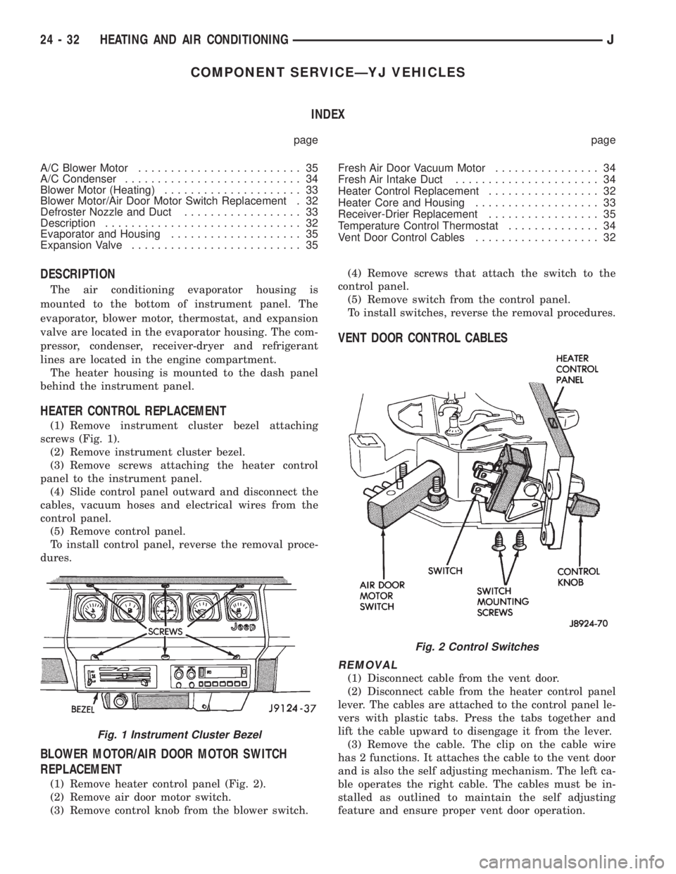
(1) Remove instrument cluster bezel attaching
screws (Fig. 1).
(2) Remove instrument cluster bezel.
(3) Remove screws attaching the heater control
panel to the instrument panel.
(4) Slide control panel outward and disconnect the
cables, vacuum hoses and electrical wires from the
control panel.
(5) Remove control panel.
To install control panel, reverse the removal proce-
dures.
BLOWER MOTOR/AIR DOOR MOTOR SWITCH
REPLACEMENT
(1) Remove heater control panel (Fig. 2).
(2) Remove air door motor switch.
(3) Remove control knob from the blower switch.(4) Remove screws that attach the switch to the
control panel.
(5) Remove switch from the control panel.
To install switches, reverse the removal procedures.
VENT DOOR CONTROL CABLES
REMOVAL
(1) Disconnect cable from the vent door.
(2) Disconnect cable from the heater control panel
lever. The cables are attached to the control panel le-
vers with plastic tabs. Press the tabs together and
lift the cable upward to disengage it from the lever.
(3) Remove the cable. The clip on the cable wire
has 2 functions. It attaches the cable to the vent door
and is also the self adjusting mechanism. The left ca-
ble operates the right cable. The cables must be in-
stalled as outlined to maintain the self adjusting
feature and ensure proper vent door operation.
Fig. 1 Instrument Cluster Bezel
Fig. 2 Control Switches
24 - 32 HEATING AND AIR CONDITIONINGJ
Page 2115 of 2158
(3) Install condenser attaching screws.
(4) Connect condenser A/C line.
(5) Install radiator and fan shroud.
(6) Fill coolant system (Refer to cooling for proper
procedure).
(7) Evacuate, charge and leak test the air condi-
tioning system.
RECEIVER-DRIER REPLACEMENT
REVIEW ALL WARNINGS AND CAUTIONS IN
THIS GROUP BEFORE PERFORMING THIS
OPERATION.
REMOVAL
(1) Recover refrigerant from A/C system.
(2) Disconnect A/C lines from the receiver-drier.
(3) Remove receiver-drier attaching screws and re-
move receiver-drier.
INSTALLATION
(1) Position receiver-drier in place and install re-
ceiver-drier attaching screws.
(2) Connect A/C lines to receiver-drier.
(3) Evacuate, charge and leak test the air condi-
tioning system.
EVAPORATOR AND HOUSING
REVIEW ALL WARNINGS AND CAUTIONS IN
THIS GROUP BEFORE PERFORMING THIS
OPERATION.
REMOVAL
(1) Recover refrigerant from A/C system.
(2) Disconnect A/C lines.
(3) Remove hose clamps and dash grommet retain-
ing screws.
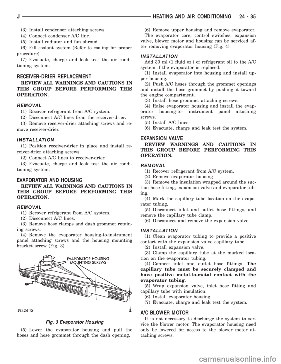
(4) Remove the evaporator housing-to-instrument
panel attaching screws and the housing mounting
bracket screw (Fig. 3).
(5) Lower the evaporator housing and pull the
hoses and hose grommet through the dash opening.(6) Remove upper housing and remove evaporator.
The evaporator core, control switches, expansion
valve, blower motor and housing can be serviced af-
ter removing evaporator housing (Fig. 4).
INSTALLATION
Add 30 ml (1 fluid oz.) of refrigerant oil to the A/C
system if the evaporator is replaced.
(1) Install evaporator into housing and install up-
per housing.
(2) Push A/C hoses through the grommet openings
and install the hose grommet by pushing it toward
the engine compartment.
(3) Install hose grommet attaching screws.
(4) Raise evaporator housing and install the evap-
orator housing-to- instrument panel attaching
screws.
(5) Install A/C lines.
(6) Evacuate, charge and leak test the system.
EXPANSION VALVE
REVIEW WARNINGS AND CAUTIONS IN
THIS GROUP BEFORE PERFORMING THIS
OPERATION.
REMOVAL
(1) Recover refrigerant from A/C system.
(2) Remove evaporator housing
(3) Remove the insulation wrapped around the suc-
tion hose fitting, expansion valve and evaporator tub-
ing.
(4) Mark the capillary tube location on the evapo-
rator tubing.
(5) Disconnect inlet and outlet hose fittings, and
remove the capillary tube clamp.
(6) Disconnect and remove the expansion valve.
INSTALLATION
(1) Clean evaporator tubing to provide a positive
contact with the expansion valve capillary tube.
(2) Install expansion valve.
(3) Clamp the capillary tube at the marked loca-
tion on the evaporator tubing.
(4) Connect inlet and outlet hose fittings.The
capillary tube must be securely clamped and
have positive metal-to-metal contact with the
evaporator tubing.
(5) Wrap expansion valve, inlet hose fitting and
capillary tube with insulation.
(6) Install evaporator housing.
(7) Evacuate, charge and leak test the system.
A/C BLOWER MOTOR
It is not necessary to discharge the system to ser-
vice the blower motor. The evaporator housing need
only be lowered for access to the blower motor at-
taching screws.Fig. 3 Evaporator Housing
JHEATING AND AIR CONDITIONING 24 - 35
Page 2118 of 2158
EMISSION CONTROL SYSTEMS
CONTENTS
page page
COMPONENT REMOVAL/INSTALLATION....... 7
EMISSION CONTROLS.................... 4GENERAL INFORMATION.................. 1
GENERAL INFORMATION
INDEX
page page
Catalytic Convertor......................... 1
DRB Scan Tool............................ 2
Exhaust Gas Recirculation (EGR) System........ 1Service Reminder Indicator (SRI) Lamp.......... 1
Vacuum Hose Routing Schematics............. 2
Vehicle Emission Control Information (VECI) Label . 1
Throughout this group, references are made to par-
ticular vehicle models by alphabetical designation
(XJ or YJ) or by the particular vehicle nameplate. A
chart showing a breakdown of alphabetical designa-
tions is included in the Introduction section at the
beginning of this manual.
Information on the air cleaner housing and the air
cleaner element can be found in Group 14, Fuel Sys-
tems.
CATALYTIC CONVERTOR
Refer to Group 11, Exhaust System and Intake
Manifold for information.
EXHAUST GAS RECIRCULATION (EGR) SYSTEM
An EGR system is not used with the 2.5L 4 cylin-
der or the 4.0L 6 cylinder engine on any XJ or YJ
model.
SERVICE REMINDER INDICATOR (SRI) LAMP
The instrument panel mounted SRI lamp was for-
merly referred to as the emission maintenance re-
minder (EMR) lamp. It isnot usedon any XJ or YJ
model for the 1995 model year.
VEHICLE EMISSION CONTROL INFORMATION
(VECI) LABEL
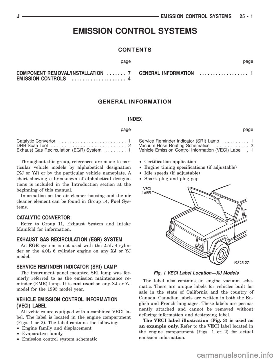
All vehicles are equipped with a combined VECI la-
bel. The label is located in the engine compartment
(Figs. 1 or 2). The label contains the following:
²Engine family and displacement
²Evaporative family
²Emission control system schematic²Certification application
²Engine timing specifications (if adjustable)
²Idle speeds (if adjustable)
²Spark plug and plug gap
The label also contains an engine vacuum sche-
matic. There are unique labels for vehicles built for
sale in the state of California and the country of
Canada. Canadian labels are written in both the En-
glish and French languages. These labels are perma-
nently attached and cannot be removed without
defacing information and destroying label.
The VECI label illustration (Fig. 3) is used as
an example only.Refer to the VECI label located in
the engine compartment (Figs. 1 or 2) for actual
emission information.
Fig. 1 VECI Label LocationÐXJ Models
JEMISSION CONTROL SYSTEMS 25 - 1
Page 2119 of 2158

VACUUM HOSE ROUTING SCHEMATICS
The vacuum hose routing schematics are used
as examples only.If there are any differences be-
tween these schematics and the Vehicle Emission
Control Information (VECI) label schematics, those
shown on the VECI label should be used.
DRB SCAN TOOL
For operation of the DRB scan tool, refer to the ap-
propriate Powertrain Diagnostic Procedures service
manual.
Fig. 2 VECI Label LocationÐYJ Models
Fig. 3 VECI LabelÐTypical
25 - 2 EMISSION CONTROL SYSTEMSJ